
IM5140 - Inductive sensor IFM - Free user manual and instructions
Find the device manual for free IM5140 IFM in PDF.
| Product type | Inductive proximity sensor with analog output |
| Model | IM5140 |
| Brand | IFM |
| Category | Inductive sensor |
| Dimensions (estimated) | Diameter: 12 mm, Length: 50 mm (typical for IMC series) |
| Weight (estimated) | Approximately 30 g |
| Power supply | DC 10…30 V |
| Analog output | 0…10 V or 4…20 mA (depending on version) |
| Detection range (operating range) | Indicated on the device label (standard measurement on mild steel) |
| LED indicators | Green LED (power present), Yellow LED (object in operating zone) |
| Active face material | Plastic or metal (depending on version) |
| Mounting | Flush mount, screwed onto mounting base |
| Active face orientation | Frontal by default, adjustable laterally (loosen the fixing screw) |
| Electrical connection | By qualified electrician, comply with national/international standards |
| Load resistance | Do not exceed or fall below the specification in the datasheet |
| Minimum clearance zone (mounting in metal) | See diagram in the manual |
| Maintenance | No maintenance required, keep active face free of metal deposits |
| Safety | Installation de-energized, by qualified personnel |
| Spare parts | Not applicable (device not repairable) |
| General information | Manual available in free PDF on notice-facile.com |
Frequently Asked Questions - IM5140 IFM
User questions about IM5140 IFM
0 question about this device. Answer the ones you know or ask your own.
Ask a new question about this device
Download the instructions for your Inductive sensor in PDF format for free! Find your manual IM5140 - IFM and take your electronic device back in hand. On this page are published all the documents necessary for the use of your device. IM5140 by IFM.
USER MANUAL IM5140 IFM
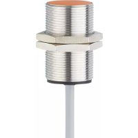
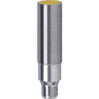
Inductive sensor IMC, flush with analogue output
Function and features
Inductive proximity switches with analogue output determine without contact the distance between object and sensing face. For the operating range (s) see the label of the unit (values are to standard mild steel targets, for other metals correction factors apply).
The analogue signal can be a voltage (0...10 V) or current (4...20 mA) depending on the type of unit.
Installation
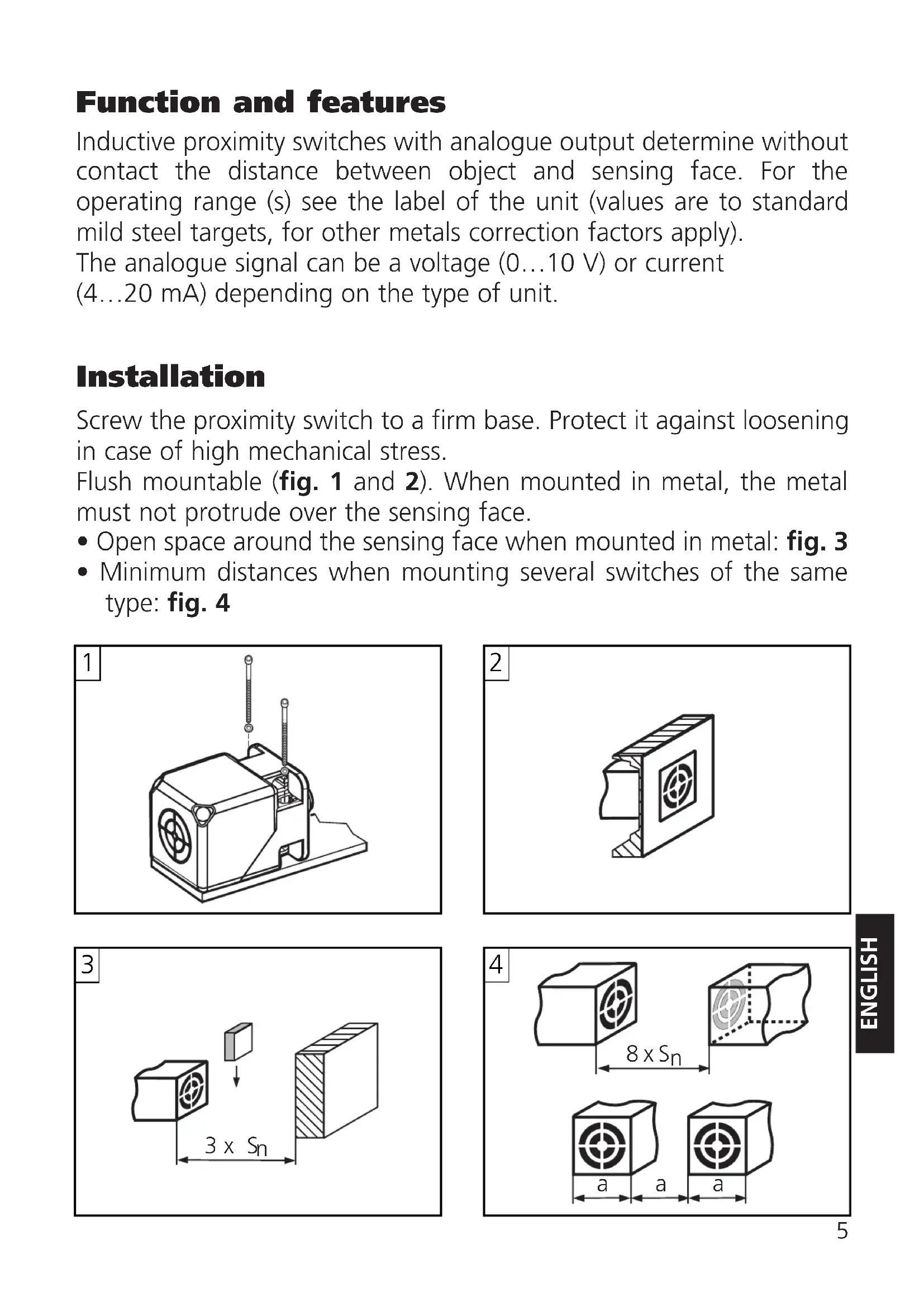
Screw the proximity switch to a firm base. Protect it against loosening in case of high mechanical stress.
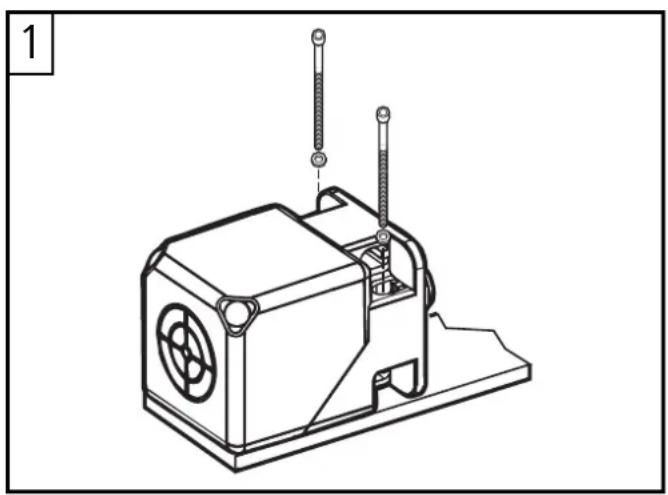
Flush mountable (fig. 1 and 2). When mounted in metal, the metal must not protrude over the sensing face.
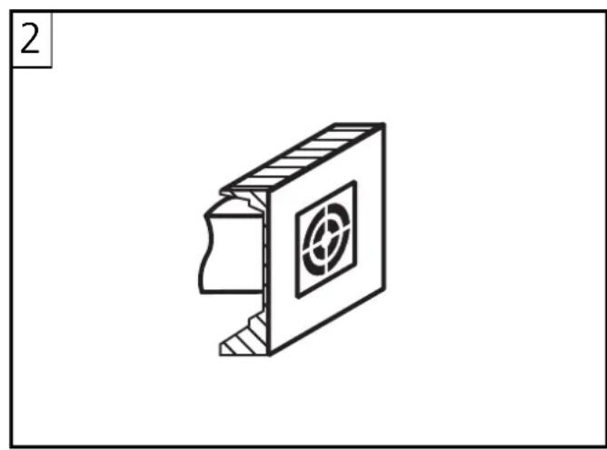
- Open space around the sensing face when mounted in metal: fig. 3
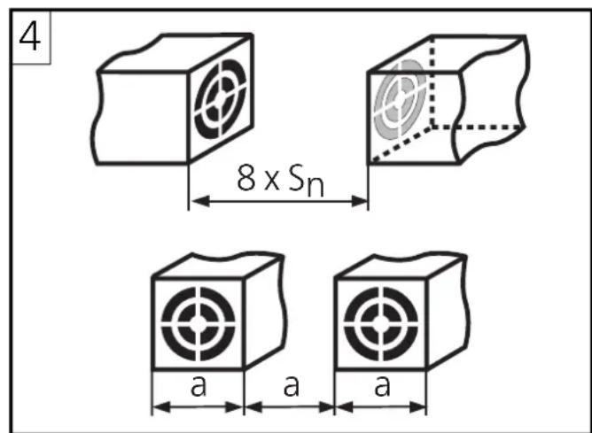
- Minimum distances when mounting several switches of the same type: fig. 4

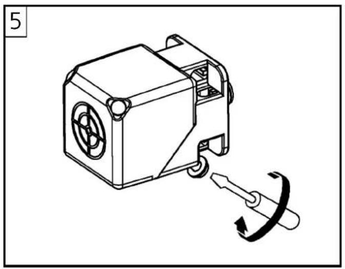
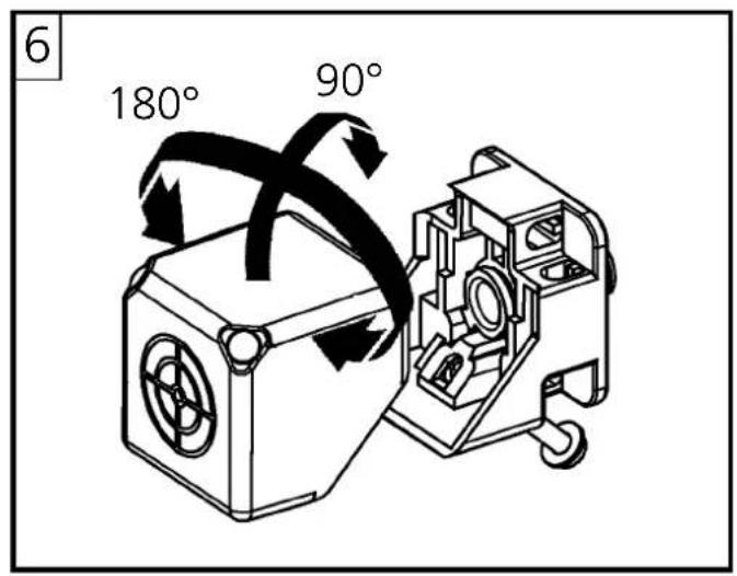
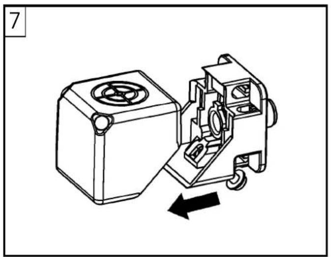
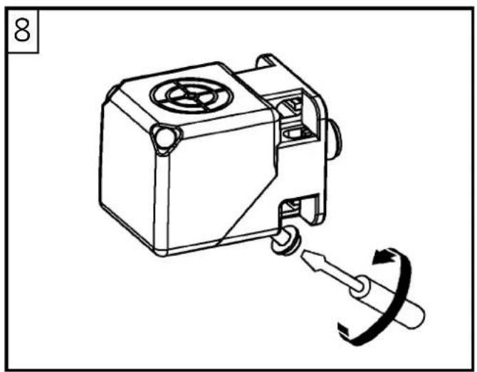
Alignment of the sensing face
On delivery, the sensing face is facing the front (fig. 5). The sensing face can be turned to the side (fig. 8) by loosening the fixing screw and turning the sensor block (fig. 5-8).
Electrical connection
The unit must be connected by an electrician.
The national and international regulations for the installation of electrical equipment must be adhered to.
Disconnect power. Connect the unit as indicated on the type label.
The load resistance must not be higher or lower than specified in the data sheet.
Setup / Operation
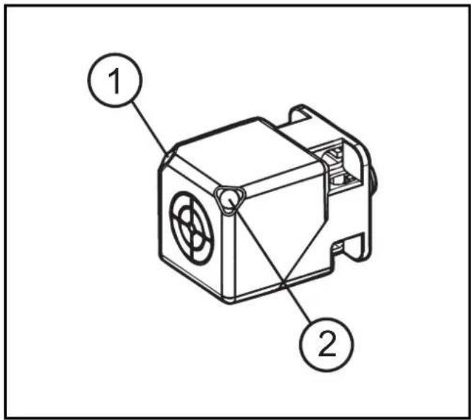
(1) Green LED.
Lights when supply voltage is applied.
(2) Yellow LED.
Is lit permanently when the object is in the operating range. The LED starts to flash outside the operating range.
Output characteristics (diagram)
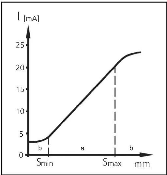
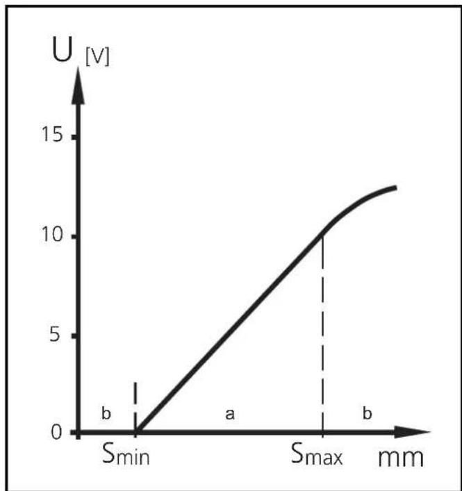
a: Operating range (s) --> LED is lit permanently
b: Warning / fault range --> LED flashes
S_ = start point of operating range
S_ = end point of operating range
The operation of the sensor is maintenance-free.
For perfect functioning: Keep the sensing face and the open space free of metal deposits and foreign bodies.


Brand : IFM
Model : IM5140
Category : Inductive sensor