
GG712S - Inductive sensor IFM - Free user manual and instructions
Find the device manual for free GG712S IFM in PDF.
| Product type | Inductive safety sensor |
| Brand | IFM |
| Model | GG712S |
| Valid area | 1...5 mm (with FE360 target) |
| Safe switching distance s_ar | > 7 mm |
| Supply voltage | 24 V DC (19.2...30 V DC) |
| Current consumption | < 30 mA |
| Outputs | 2 × OSSD (A1 and A2), PNP |
| Max. output current | 100 mA |
| Short-circuit protection | Yes |
| Response time (safe state) | ≤ 1 ms |
| Response time (valid) | ≤ 1 ms |
| Risk time | ≤ 20 ms |
| LED indication | Yellow (signal), Green (power) |
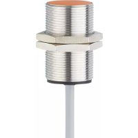
| Connection | M12 connector, gold-plated contacts |
| Housing material | Brass coated with white bronze, PBT |
| Weight | 0.14 kg |
| Mounting | Flush, thread M18 × 1 |
| Protection class | IP65 / IP67 |
| Ambient temperature | -25...70 °C or 10...40 °C depending on operating time |
| Safety standards | EN ISO 13849-1 (PL d), IEC 61508 (SIL 2), IEC 62061 (SILcl 2) |
| Mission time | ≤ 175,200 h (20 years) |
| Maintenance | No maintenance required under normal operation |
| Repairability | Repair by manufacturer only |
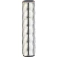
| Supplied accessories | 2 M18 fixing nuts |
Frequently Asked Questions - GG712S IFM
User questions about GG712S IFM
0 question about this device. Answer the ones you know or ask your own.
Ask a new question about this device
Download the instructions for your Inductive sensor in PDF format for free! Find your manual GG712S - IFM and take your electronic device back in hand. On this page are published all the documents necessary for the use of your device. GG712S by IFM.
USER MANUAL GG712S IFM
natural_image
Abstract geometric logo with stylized white lines and circular elements on gray background (no text or symbols)CE
natural_image
Technical line drawing of a mechanical connector or fitting (no text or symbols)
BG български
- According to the machine directive 2006/42/EC the original operating instructions and a translation of these operating instructions into the language or languages of the EU user country must be provided when a unit or protective system is put into operation within the member countries of the European Union (EU).
- If no operating instructions or EC declaration of conformity is supplied with this product in the language of the EU user country, these can be requested from your dealer (see delivery note) or manufacturer (see cover sheet / back).
- Only qualified personnel is allowed to set up the product. Furthermore, we expressly point out that any liability is excluded resulting from putting the unit into operation without the corresponding operating instructions in the language of the EU user country.
ES Español
1 Preliminary note ....3
1.1 Symbols used ....3
1.2 Warning signs used ....3
2 Safety instructions ....4
2.1 Safety-related requirements regarding the application ....4
3 Items supplied....5
4 Functions and features ....5
5 Function....6
5.1 Enable zone 6
6 Installation....7
6.1 Protection against simple defeating ....7
7 Electrical connection ....8
8 Operation....8
8.1 Switching state of the outputs ....8
8.1.1 The safe state ....8
8.1.2 The switched state 8
8.1.3 Output characteristics ....8
8.1.4 Cross fault / short circuit 9
8.2 Response times ....10
8.3 LED display 11
9 Technical data ....12
10 Troubleshooting ....14
11 Maintenance, repair and disposal ....14
12 Terms and abbreviations .... 15
1 Preliminary note
The instructions are part of the unit. They are intended for authorised persons according to the EMC, Low Voltage and Machinery Directives and safety regulations.
The instructions contain information about the correct handling of the product. Read the instructions before use to familiarise yourself with operating conditions, installation and operation. Follow the safety instructions.
1.1 Symbols used

▶ Instructions
→ Cross-reference

Important note
Non-compliance can result in malfunction or interference.

Information
Supplementary note.
LED on
○ LED off
LED flashes (2 Hz)
LED flashes quickly (5 Hz)
1.2 Warning signs used

WARNING
Warning of serious personal injury. Death or serious irreversible injuries may result.
2 Safety instructions
- Follow the operating instructions.
- Improper use may result in malfunctions of the unit. This can lead to personal injury and/or damage to property during operation of the machine. For this reason note all remarks on installation and handling given in this document. Also adhere to the safety instructions for the operation of the whole installation.
- In case of non-observance of notes or standards, especially when tampering with and/or modifying the unit, any liability and warranty is excluded.
- If the sensor is damaged, the safety function cannot be guaranteed.
- Errors caused by damage cannot be detected by the sensor.
- The unit must be installed, connected and put into operation by a qualified electrician trained in safety technology.
- The applicable technical standards for the corresponding application must be complied with.
- For installation the requirements according to EN 60204 must be observed.
- In case of malfunction of the unit please contact the manufacturer. Tampering with the unit is not allowed.
- Disconnect the unit externally before handling it. Also disconnect any independently supplied relay load circuits.
- After installation, maintenance or repair of the system perform a complete function check.
- Use the unit only in specified environmental conditions ( 9 Technical data). In case of special operating conditions please contact the manufacturer.
• Use only as described below ( 4).
2.1 Safety-related requirements regarding the application
It must be ensured that the safety requirements of the respective application correspond to the requirements stated in these instructions.

WARNING
Failure of the safety function
When used outside of the defined environmental conditions, the safety-related function of the sensor cannot be guaranteed.
▶ Use only in accordance with the defined environmental conditions ( 9 Technical data).
Use of the sensor in the vicinity of chemical and biological media (solid, liquid, gaseous) as well as ionising radiation is not permitted.
UK
Observe the following requirements:
▶ Take measures to avoid metallic objects being placed on the sensing face unintentionally.
▶ Adhere to EN 14119 for interlocking devices associated with guards.
▶ Adhere to the principle of normally closed operation for all external safety circuits connected to the system.
In case of faults within the fail-safe sensor which result in the defined safe state: take measures to maintain the safe state when the complete control system continues to be operated.
▶ Replace damaged units.
3 Items supplied
1 fail-safe sensor GG712S with 2 M18 fixing nuts,
1 original operating instructions GG712S, ident no. 11491851.
If one of the above-mentioned components is missing or damaged, please contact one of the ifm branch offices.
4 Functions and features
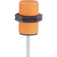
The fail-safe inductive sensor GG712S detects metal without contact.
Safety function SF: the safe state (output stage switched off; logic "0") is achieved when undamping greater than or equal to the safe switch-off distance s_ar ( 9 Technical data).
Also observe the notes on installation of the sensor ( 6 Installation).
The fail-safe inductive sensor is a proximity device with defined behaviour under fault conditions (PDDB) to IEC 60947-5-3.
The fail-safe sensor conforms to Performance Level d according to EN ISO 13849-1 as well as to the requirements SIL 2 to IEC 61508 and meets SILcl 2 to IEC 62061.
The unit corresponds to the classification I1A18SP2 to IEC 60947-5-2 for flush installation ( 6 Installation).
The fail-safe inductive sensor has been certified by TÜVNord.
5 Function
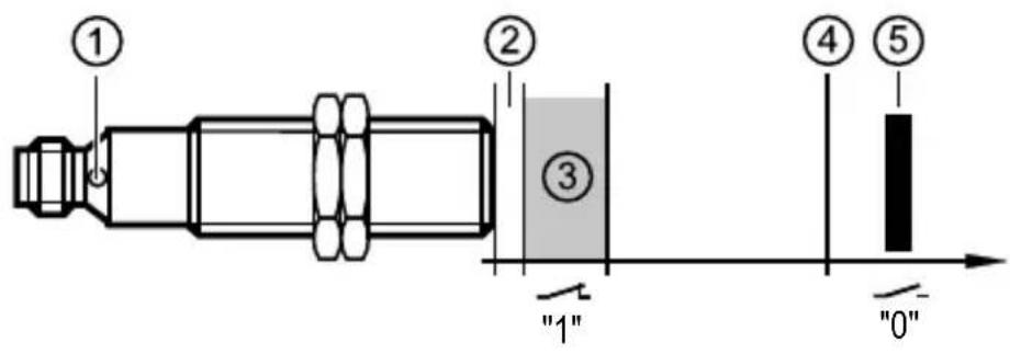
1: dual LED: signal (yellow); power (green)
2: close zone
3: enable zone
4: safe switch-off distance s_ar
5: target
5.1 Enable zone
The outputs (OSSD) are only enabled when a damping target is present in the enable zone. Outside this enable zone the outputs remain switched off.
The safe switch-off distance s_ar is > 7 mm.

The enable zone is different if damping elements which deviate from the standard target plate in terms of material, form and size are used.
Enable zone for selected materials*:
| Material Enable zone |
| FE360 (= mild steel) 1...5 mm |
| Stainless steel 0...3.5 mm |
| AIMg3G22 0...2.0 mm |
| CuZn37 0...2.0 mm |
| Copper 0...1.5 mm |
* Typical values for damping with a reference target of 18 x 18 x 1 mm and non-flush installation to IEC 60947-5-2 at an ambient temperature of 20 °C.

Depending on the characteristics of the damping element there may be no close zone.
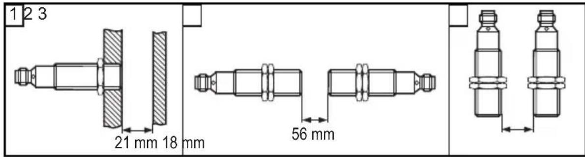
6 Installation
The unit is flush mountable according to IEC 60947-5-2, type I1A18SP2.
▶ Ensure the unit cannot work loose (tightening torque ≤ 25 Nm).
▶ Adhere to the installation conditions in accordance with the figures 1 to 3:
UK
▶ Tighten the socket according to the manufacturer's indications. Observe the tightening torque for the ifm socket (e.g. EVxxxx: 0.6...1.5 Nm).
6.1 Protection against simple defeating
The fail-safe sensor reacts to metal objects, e.g. the frame of a safety door. Other metal objects that are not intended to enable the sensor must not be allowed to enable the fail-safe sensor unintentionally.

▶ Take measures to prevent metal objects, except the designated target, from being placed on the sensing face or in the enable zone unintentionally.
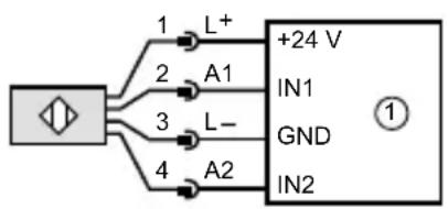
7 Electrical connection
▶ Disconnect power. Also disconnect any independently supplied relay load circuits.
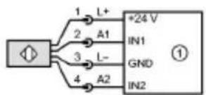
▶ Supply voltage: connect L+ to pin 1 and L- to pin 3 of the connector.

The nominal voltage is 24 V DC. This voltage may vary between 19.2 V and 30 V incl. 5 % residual ripple to EN 61131-2.

In case of a single fault the supply voltage must not exceed a maximum of 40 V DC. (This requires the safe separation between power supply and transformer.)
flowchart
graph TD
    A["Input"] -->|1 L+| B["+24 V"]
    A -->|2 A1| B
    A -->|3 L-| B
    A -->|4 A2| B
    B --> C["IN1"]
    B --> D["GND"]
    B --> E["IN2"]
    style B fill:#f9f,stroke:#333
    style C fill:#ccf,stroke:#333
    style D fill:#ccf,stroke:#333
    style E fill:#ccf,stroke:#333
1: safety-related logic unit *
* When there is no current flow on the output stage, back feeding > 3.5 V will lead to malfunction.
8 Operation
8.1 Switching state of the outputs
8.1.1 The safe state
The safe state is when at least one of the outputs A1 or A2 (OSSDs) is switched off (zero-current state: logic "0").
If one of the outputs A1 or A2 is switched off, the subsequent safety-related logic unit must bring the complete system into the state defined as safe.
8.1.2 The switched state
If the damping element is in the enable zone and if there is no sensor error, both outputs A1 and A2 (OSSDs) are enabled (logic "1").
8.1.3 Output characteristics
The output characteristics are compatible with the input characteristics to EN 61131-2 type 1 or 2:
| Logic "1" ≥ 15 V 2...15 mA≥ 11 V 15...30 mA |
| Logic "0" ≤ 5 V leakage current 0.2 mA |
8.1.4 Cross fault / short circuit
- A cross fault between both outputs (A1 and A2) is detected by the fail-safe sensor and results in the outputs (OSSD) being switched off at the next safety request. The outputs A1 and A2 remain switched off until the error has been removed or a voltage reset has been carried out.
- A cross fault (short circuit) between output A2 and the supply voltage results in the other output A1 being switched off in case of a safety request.
- When there is no current flow on the output stage, back feeding > 3.5 V will lead to malfunction.
- The device carries out self-tests for the switch-off capability on A2.

8.2 Response times
| Response time on safety request(removal from the enable zone) | ≤ 1 ms |
| Response time when approaching the enable zone (enable time) | ≤ 1 ms |
| Risk time / response time for safety-related faults ≤ 20 ms | |
| Simultaneity of switching on and off of the outputs in case of a safety request | ≤ 1 ms |
| Test pulse duration t_max on A2 (1) ≤ 1 ms | |
Test pulse interval T on A2 (2) 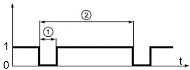 1: Test pulse duration2: Test pulse interval T T_typ T_max T_min 1: Test pulse duration2: Test pulse interval T T_typ T_max T_min | 180 ms300 ms100 ms |
8.3 LED display
| LED Operating status Outputs A1 | A2(OSSD) (OSSD) | ||
| ○ Signal○ Power | No voltage supply Both outputs switched off 0 0 | ||
| ○ Signal※ Power | Undervoltage 1 | 00 | |
| ○ Signal※ Power | Overvoltage Both outputs switched off 0 0 | ||
| Sensor fault(→ 10 Troubleshooting) | One output or bothoutputs switched off | 01100 | |
| ● Signal● Power | Damping element in the enable zone | Both outputs enabled 1 1 | |
| Damping element in the close zone | Output A2 is switched off 1 | 0 | |
UK

9 Technical data
CE

TUV NORD
Product characteristics
Fail-safe inductive sensor
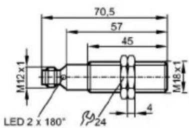
Metal thread M18 x 1
M12 connector
Enable zone 1...5 mm; [f] flush mountable
Complies with the requirements:
EN ISO 13849-1: 2015 category 2 PL d (can be used in applications up to cat. 3)
IEC 61508: SIL 2
IEC 62061: SILcl 2
Application
Type of operation continuous operation (maintenance-free)
Electrical data
Electrical design DC PNP
Operating voltage 24 DC (19.2...30 [V])
Rated insulation voltage 30 [V]
Current consumption < 30 [mA]
Protection class III
Reverse polarity protection yes
Outputs
Output function 2 x OSSD (A1 and A2)
Output data Interface type C class 1
Output voltage at 24 V compatible with EN 61131-2 inputs type 1, 2
Voltage drop < 2.5; (30 mA) [V]
Current rating [mA] 100
Short-circuit protection yes
Max. capacitive load CL_max [nF] 20
Range
Enable zone [mm] 1...5
Safe switching off distance s(ar) [mm] 7
Reaction times
Power-on delay time [s] 1
Response time to safety request [ms] ≤ 1
Response time when approaching [ms] the enable zone (enable time) ≤ 1
Risk time (response time for safety[ms] -related faults) ≤ 20
Environment
| Applications Class C to EN 60654-1 weatherproof application | |
| Ambient temperature -25...70, for se[°C]e life ≤ 87600 h | 10...40, for service life ≤ 175200 h |
| Rate of temperature change 0.5 [K/min] | |
| Max. relative air humidity 5...95, briefly] | 5...70, permanently |
| Air pressure 80...106 [kPa] | |
| Height above sea level ≤ 2000 [m] | |
| Ionising radiation not permissible | |
| Salt spray no | |
| Protection IP 65 / IP 67 | |
Tests / approvals
| EMC | IEC 60947-5-2 | |
| IEC 60947-5-3 | ||
| EN 60947-5-2 | ||
| EN 61000-4-2 ESD: 6 kV CD / 8 kV AD | ||
| EN 61000-4-3 HF radiated: 20 V/m | ||
| EN 61000-4-4 Burst: 2 kV | ||
| EN 61000-4-6 HF conducted: 10 V | ||
| EN 61000-4-8: 30 A/m | ||
| EN 55011: class B | ||
| Shock resistance IEC 60947-5-2 | ||
| Vibration resistance | IEC 60947-5-2 | |
Safety classification
| Mission time TM | [h] | ≤ 175200, (20 years) |
| Safety-related reliability PFHd | [1/h] | 1.0E-07 |
Mechanical data
| Mounting | flush mountable | |
| Housing materials | Brass white bronze coated; PBT | |
| Weight | [kg] | 0.14 |
Displays / operating elements
| Display | LED yellow (signal), LED green (power) |
Electrical connection
| Connection | M12 connector; Gold-plated contacts |
| Wiring |

flowchart
graph TD
    A["Microcontroller"] -->|1 L+| B["*24 V"]
    A -->|2 A1| B
    A -->|3 L-| B
    A -->|4 A2| B
    B --> C["IN1"]
    B --> D["GND"]
    B --> E["IN2"]
    style A fill:#f9f,stroke:#333
    style B fill:#ccf,stroke:#333
    style C fill:#fff,stroke:#333
    style D fill:#fff,stroke:#333
    style E fill:#fff,stroke:#333
1: Safety-related logic unit
Accessories
| Accessories (included) | 2 lock nuts | |
| Remarks | ||
| Remarks | Unless stated otherwise, all data refer to the 18x18x1 mm reference target plate to IEC 60947-5-2 (FE360 = mild steel) over the whole temperature range. | |
| Pack quantity | [piece] | 1 |
ifm electronic gmbh • Friedrichstraße 1 • 45128 Essen — GB — GG712S-03 — 19.05.2016
10 Troubleshooting
LED display → 8.3
| Problem Possible cause Troubleshooting | ||
| No LED display No voltage | supply Apply voltage | |
| Power LED flashes and sensor does not switch | UndervoltageOvervoltage | Correct the voltage(→9 Technical data) |
| Sensor does not switch, not even after undamping and redamping | Sensor was brought into the safe state (logic "0"). Cause:cross fault between both outputs A1 and A2cross fault between output A2 and the supply voltageerror in the sensor detected | Remove the cross faultReplace the unit |
| No close zone Due to its characteristics(material, form, size), the damping element displaces the enable zone until directly in front of the sensing face | If possible, change the material, form or size of the damping element (→5.1 Enable zone) | |
11 Maintenance, repair and disposal
If used correctly, no maintenance and repair measures are necessary.
Only the manufacturer is allowed to repair the unit.
After use dispose of the unit in an environmentally friendly way in accordance with the applicable national regulations.
12 Terms and abbreviations
| OSSD Output Signal Switch Device | ||
| PDDB Proximity devices with definedbehaviour under fault conditions | ||
| PFH(PFH _D ) | Probability of (dangerous)Failure per Hour | |
| PL Performance Level PL to EN ISO 13849-1 | ||
| SIL Safety | Integrity Level SIL 1-4 to IEC 61508. The higher the SIL, the lower the probability that a safety function will fail. | |
| SIL _cl | Safety Integrity Level _claim limit | According to IEC 62061 |
| T_M | Mission time Lifetime to EN 60947-5-3(= max. service life) | |
UK
Contenu
Tests / Homologations
EU declaration of conformity
The EU declaration of conformity applies to the following units:
This declaration of conformity is issued under the sole responsibility of the manufacturer.
We confirm the conformity to the applicable regulations of the European directive(s):
2006/42/EC – to article 12 (3) a)
2006/42/CE – selon article 12 (3) a)
Reference to the standard(s) used:
Person authorised for the compilation of the technical documents
(Place and date of issue)
Klaus Unger / Managing Director
Declaration of Conformity
ifm electronic gmbh
Friedrichstraße 1
45128 Essen
Germany
Telefon: +49 (0)201 / 24 22 - 0
Telefax: +49 (0)201 / 24 22 - 1200
Internet: www.ifm.com
The declaration of conformity applies to the following units:
G.71.S
This declaration of conformity is issued under the sole responsibility of the manufacturer.
We confirm the conformity to the essential requirements of the UK Regulation(s):
2008 No. 1597 Supply of Machinery (safety) Regulations to PART 3 - 11(2)(a) 2012 No. 3032 The Restriction of the Use of Certain Hazardous Substances in Electrical and Electronic Equipment Regulations 2016 No. 1091 Electromagnetic Compatibility Regulations
The following standard(s) was (were) applied:
EN 62061:2005+AC:2010+A1:2013+A2:2015
Person authorised for the Compilation of the technical documents
Mr. R. Birkett, ifm electronic ltd, Efector House Kingsway Business Park Oldfield Road, TW12 2HD, Hampton, GB
Tettnang, 06.10.2022
(Place and date of issue)

(Signature) (name, function) Klaus Unger / Managing Director
Document No.: 9000207


- BG български
- ES Español
- Preliminary note
- Symbols used
- Warning signs used
- WARNING
- Safety instructions
- Safety-related requirements regarding the application
- Items supplied
- Functions and features
- Function
- Enable zone
- Installation
- Protection against simple defeating
- Electrical connection
- Operation
- Switching state of the outputs
- The safe state
- The switched state
- Output characteristics
- Cross fault / short circuit
- Response times
- LED display
- Technical data
- Product characteristics
- Application
- Electrical data
- Outputs
- Range
- Reaction times
- Troubleshooting
- Maintenance, repair and disposal
- Contenu
- EU declaration of conformity
- Declaration of Conformity
Brand : IFM
Model : GG712S
Category : Inductive sensor