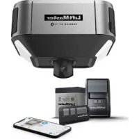
050ACTWFMC - Garage door opener LIFT-MASTER - Free user manual and instructions
Find the device manual for free 050ACTWFMC LIFT-MASTER in PDF.
| Product Type | Garage Door Opener |
| Brand | LIFT-MASTER |
| Model | 050ACTWFMC |
| Power Supply | Mains and backup battery |
| Connectivity | Built-in Wi-Fi for connection to myQ network |
| Main Functions | Travel programming, remote control, safety reverse, obstacle detection (Protector System) |
| Remote programming | Via LEARN button on the opener (30 seconds) |
| Force adjustment | Automatic after travel limit adjustment |
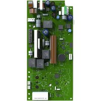
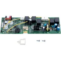
| Receiver main board | Replaceable (spare part) |
| Battery | Replacement possible (compartment in the opener) |
| Lamp lens | Removable for access (hinges and clips) |
| Safety sensors | White wires (white/black) - must be aligned and unobstructed |
| Safety reverse system | Monthly test required with a 1.5 inch object |
| Indicator lights | Flashing to confirm programming or errors |
| Maintenance | Monthly test of the reverse system; cleaning not specified |
| Manual | 12 pages, available as free PDF |
| Warning | May contain lead (California Proposition 65) |
Frequently Asked Questions - 050ACTWFMC LIFT-MASTER
User questions about 050ACTWFMC LIFT-MASTER
0 question about this device. Answer the ones you know or ask your own.
Ask a new question about this device
Download the instructions for your Garage door opener in PDF format for free! Find your manual 050ACTWFMC - LIFT-MASTER and take your electronic device back in hand. On this page are published all the documents necessary for the use of your device. 050ACTWFMC by LIFT-MASTER.
USER MANUAL 050ACTWFMC LIFT-MASTER
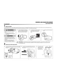
RECEIVER LOGIC BOARD REPLACEMENT
Model 050ACTWFMC
Installation
1 Before you begin
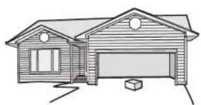
Your garde door opener has an internal gwtway located on the receiver logic board. After installing the new receiver logic board, use the myQ serial number found on the provided label to add your garage door opener to your myQ account. The products illustrated in the instructions are for reference. Your product may look different.

WARNING
To prevent possible SERIOUS INJURY or DEATH:
- Disconnect ALL electric and battery power BEFORE performing ANY service or maintenance.
CAUTION
To prevent damage to the receiver/logic board, DO NOT touch printed circuit board of replacement receiver/logic board during installation.
ALWAYS wear protective gloves and eye protection when changing the battery or working around the battery compartment.
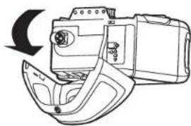
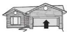
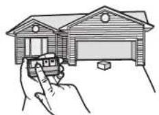
1.1 Remove the light lens by pulling the top sides of the light lens and rotate the light lens down. Squeeze the light lens clips to remove lens from end panel.
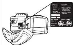
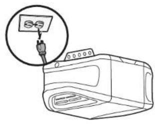
1.2 To maintain your warranty, place the provided label over the existing label on the end panel of the garage door opener.
1.3 Disconnect power to the garage door opener.

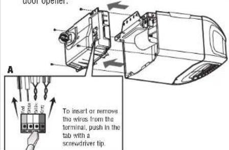
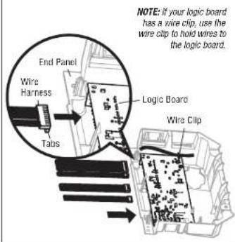
2 Remove the receiver logic board
2.1 Disconnect the wires from the quick-connect terminals (A) Remove the receiver logic board end panel from the garage door opener.
2.2 Unplug the wire harnesses from the receiver logic board. You may need needle-nosed pliers to remove the harnesses.
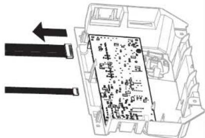
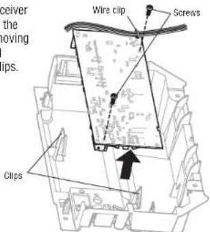
2.3 Remove the receiver logic board from the end panel by removing the 2 screws and releasing the 2 clips.

Install new receiver logic board
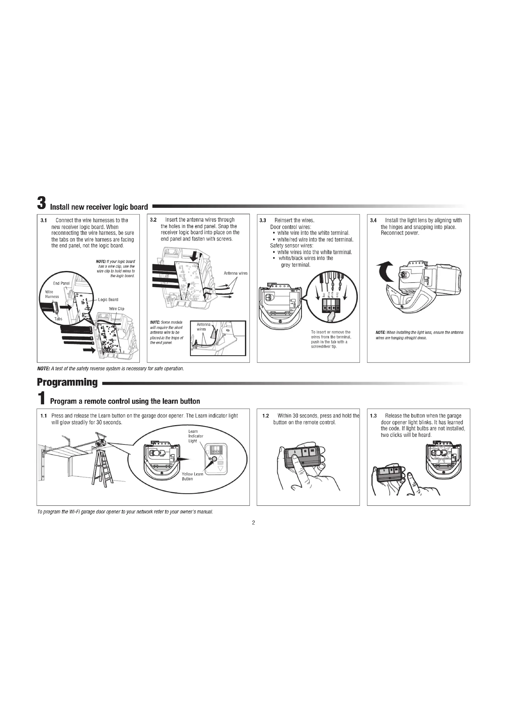
3.1 Connect the wire harnesses to the new receiver logic board. When reconnecting the wire harness, be sure the tabs on the wire harness are facing the end panel, not the logic board.
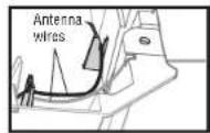
3.2 Insert the antenna wires through the holes in the end panel. Snap the receiver logic board into place on the end panel and fasten with screws.
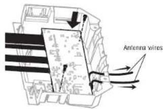
NOTE: Some models will require the short anthrax worm to be placed in the traps of the end panel.
3.3 Reinsert the wires.
Door control wires:
- white wire into the white terminal
white/red wire into the red terminal.
Safety sensor wires:
-
white wires into the white terminal.
-
white/black wires into the
grey terminal.
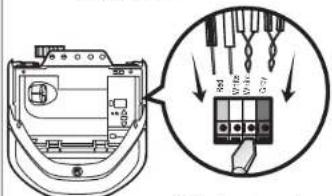
To insert or remove the wires from the terminal push in the tab with a screwdriver tip.
3.4 Install the light lens by aligning with the hinges and snapping into place. Reconnect power.

NOTE: When installing the light lens, ensure the antenna wires are hanging straight down.
NOTE: A test of the safety reverse system is necessary for safe operation.
Programming

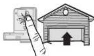
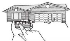
Program a remote control using the learn button
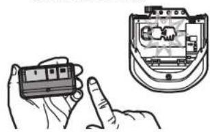
1.1 Press and release the Learn button on the garage door opener. The Learn indicator light will glow steadily for 30 seconds.
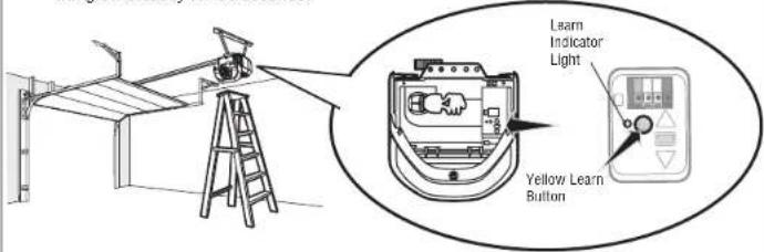
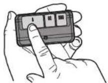
1.2 Within 30 seconds, press and hold the button on the remote control.
1.3 Release the button when the garage door opener light blinks. It has learned the code. If light bulbs are not installed, two clicks will be heard.
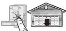
To program the Wi-Fi garage door opener to your network refer to your owner's manual.
Adjustment
1 Program the travel
WARNING
Without a properly installed safety reversal system, persons (particularly small children) could be SERIOUSLY INJURED or KILLED by a closing garage door.
- Incorrect adjustment of garage door travel limits will interfere with proper operation of safety reversal system.
AfterANY adjustments are made, the safety reversal system MUST be tested. Door MUST reverse on contact with 1-1/2" (3.8 cm) high object (or 2x4 laid flat) on floor
While programming the travel, the UP and DOWN buttons can be used to move the door as needed. The Safety Reversing Sensors will be disconnected during the Program the Travel process. During the Automatic Force Setup the door will automatically open and close.
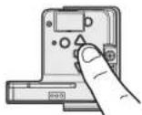
1.1 Press and hold the Adjustment Button until the UP Button begins to flash and/or a beep is heard.
The Safety Reversing Sensors will be disconnected during the Program the Travel process.
1.2 Press and hold the UP Button until the door is in the desired UP position.
1.30ncethe door is in the desired UP position press and release the Adjustment Button. The garage door opener lights will flash twice and the DOWN Button will begin to flash.
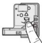
1.4 Press and hold the DOWN button until the door is in the desired DOWN position.
1.5 Once the door is in the desired DOWN position press and release the Adjustment Button. The garage door opener lights will flash twice. Program the Travel is now complete. If the garage door opener lights flash 5 times, then programming has timed out and the Travel Limits have not been set. Please restart the Program the Travel process.
1.6 Add the Step Saver sticker under the yellow program button.
Automatic Force Set Up
Once both the up and down positions have been manually set, the Safety Reversing Sensors will reconnect and become operational. Then, the opener will enter a force-sensing operation by automatically moving the door open and close. The garage door opener will sound an audible and visual alert before automatically opening and closing the door. The garage door opener will beep three times, confirming that the Automatic Force Setup completed successfully. Adjustment is complete.
If you hear one long beep after the door attempts to move, then the Automatic Force Set Up has not completed successfully. Please start over at step 1 of Program the Travel...
3 Test the Safety Reversal System
WARNING
Without a properly installed safety reversal system, persons (particularly small children) could be SERIOUSLY INJURED or KILLED by a closing garage door.
- Safety reversal system MUST be tested every month.
- After ANY adjustments are made, the safety reversal system MUST be tested. Door MUST reverse on contact with 1-1/2" high (3.8 cm) object (or 2x4 ladd flat) on the floor.
3.1 With the door fully open, place a 1-1/2 inch (3.8 cm) board (or a 2x4 laid flat) on the floor, centered under the garage door.
3.2 Press the remote control push button to close the door. The door MUST reverse when it makes contact with the board.
If the door stops but does not reverse:
- Repeat Program the Travel (see Adjustment Step 1);
- Repeat the Safety Reversal test. If the test continues to fail, call a trained door systems technician.
4 Test the Protector System
WARNING
Without a properly installed safety reversing sensor, persons (particularly small children) could be SERIOUSLY INJURED or KILLED by a closing garage door.
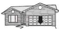
4.1 Open the door. Place an obstruction in the path of the door.
4.2Press the remote control push button to close the door. The door will not move more than an inch (2.5 cm).
The garage door opener will not close from a remote control if the LED in either safety reversing sensor is off (alerting you to the fact that the sensor is misaligned or obstructed).
If the garage door opener closes the door when the safety reversing sensor is obstructed (and the sensors are no more than 6 inches [15 cm] above the floor), call for a trained door systems technician.
REEMPLACEMENT DU RÉCEPTEUR DE LA CARTE MÈRE
Modèle 050ACTWFMC