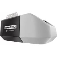
041D80061 - Electric garage door opener LIFT-MASTER - Free user manual and instructions
Find the device manual for free 041D80061 LIFT-MASTER in PDF.
| Product Type | Garage door opener motor kit (DC) |
| Brand | LIFT-MASTER |
| Model | 041D80061 |
| Power Supply | Mains and backup battery |
| Drive Type | Belt or chain (depending on model) |
| Main Functions | Motorized opening and closing of garage door, limit switch programming, safety reversal |
| Programming | UP, DOWN and SET buttons for adjusting open and close positions |
| Safety | Safety reversal sensors, obstacle stop system, emergency release |
| Maintenance | Monthly test of safety reversal system, check belt/chain tension |
| Spare Parts and Repairability | Replaceable motor assembly, removable travel module, reusable gear and circlip |
| Dimensions (estimated) | Approximately 30 x 20 x 15 cm (motor only) |
| Weight (estimated) | Approximately 3 kg (motor only) |
Frequently Asked Questions - 041D80061 LIFT-MASTER
User questions about 041D80061 LIFT-MASTER
0 question about this device. Answer the ones you know or ask your own.
Ask a new question about this device
Download the instructions for your Electric garage door opener in PDF format for free! Find your manual 041D80061 - LIFT-MASTER and take your electronic device back in hand. On this page are published all the documents necessary for the use of your device. 041D80061 by LIFT-MASTER.
USER MANUAL 041D80061 LIFT-MASTER
Motor Kit for DC Garage Door Openers
MODELS 041D1739-1, 041D1624-1 AND 041D8006-1
INTRODUCTION
The images throughout these instructions are for reference and your product may look different.
You will need:
- 1/4" magnetic nut driver
- Long-nosed pliers
- 5/16" long-shafted magnetic nut driver and socket
- Flathead screwdriver
WARNING
To prevent possible SERIOUS INJURY or DEATH: - Disconnect ALL electric and battery power BEFORE performing ANY service or maintenance.
CAUTION
The garage door MUST be in the fully closed position during installation. ALWAYS wear protective gloves and eye protection when changing the battery or working around the battery compartment.

WARNING: This product can expose you to chemicals including lead, which are known to the State of California to cause cancer or birth defects or other reproductive harm. For more information go to www.P65Warnings.ca.gov
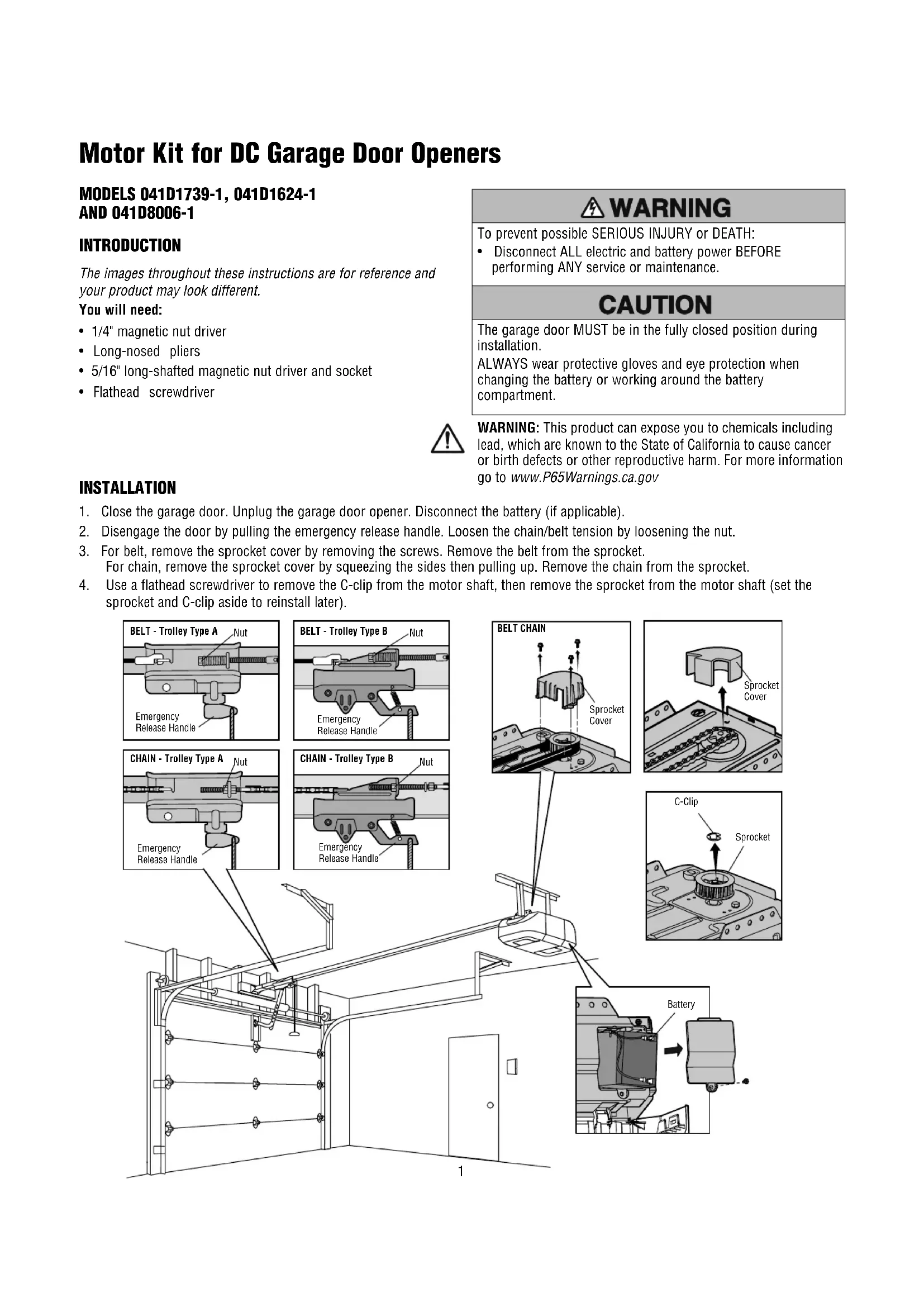
INSTALLATION
- Close the garage door. Unplug the garage door opener. Disconnect the battery (if applicable).
- Disengage the door by pulling the emergency release handle. Loosen the chain/belt tension by loosening the nut.
- For belt, remove the sprocket cover by removing the screws. Remove the belt from the sprocket. For chain, remove the sprocket cover by squeezing the sides then pulling up. Remove the chain from the sprocket.
- Use a flathead screwdriver to remove the C-clip from the motor shaft, then remove the sprocket from the motor shaft (set the sprocket and C-clip aside to reinstall later).
text_image
BELT - Trolley Type A Nut Emergency Release Handle BELT - Trolley Type B Nut Emergency Release Handle BELT CHAIN Sprocket Cover CHAIN - Trolley Type A Nut Emergency Release Handle CHAIN - Trolley Type B Nut Emergency Release Handle C-Clip Sprocket BatteryINSTALLATION
-
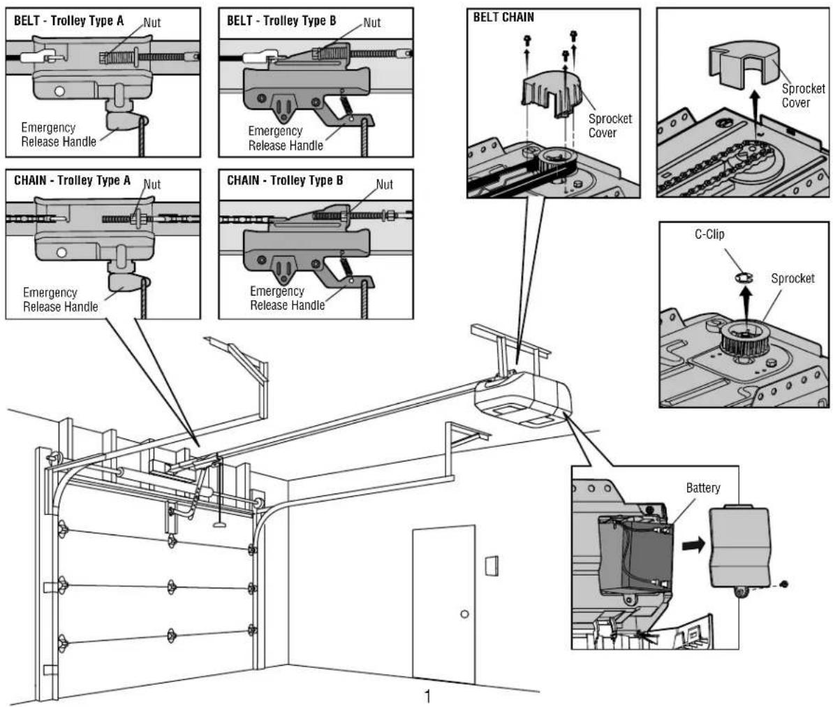
Disassemble the garage door opener:
-
Remove the light lens (if applicable).
- Disconnect the wires from quick-connect terminals on the logic board.
- Remove the end panel with the logic board.
- Disconnect all wire harnesses from the logic board.
- Remove the cover.
- Remove the motor assembly from the chassis.
- Remove the wire harness from the travel module on the old motor assembly. Discard the old motor assembly.
- Reassemble the garage door opener:
- Secure the new motor assembly to the chassis. (If screws are provided with the new motor assembly, use them. If screws are not provided, use the screws from the old motor assembly.)
- Attach the old travel module wire harness to the travel module on the new motor assembly.
- Reattach all the wire harnesses to the logic board (be sure the tabs on the wire harnesses are facing the end panel, not the logic board).
• Reattach the cover, then the end panel.
- Reconnect the wires to the quick-connect terminals.
- Reattach the light lens.
- Reattach the sprocket and use the C-clip to hold the sprocket in place.
• Reattach the belt/chain to the sprocket.
• Reattach the sprocket cover.
-
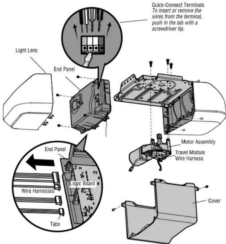
Re-engage the door. NOTE: Make sure the inner trolley engages with the outer trolley.
-
Set the belt/chain tension:
-
For chains with trolley type A, tighten the nut until the chain is a 1/4 inch (6 mm) above the base of the rail at the midpoint of the rail.
- For chains with trolley type B, tighten the nut until the chain is a 1/2 inch (13 mm) above the base of the rail at the midpoint of the rail.
-
For belts with trolley type A or B, tighten the nut until the spring is as close to 1-1/4" (3.18 cm) as possible.
-
Connect power.
Proceed to Adjustments.
text_image
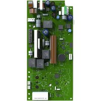
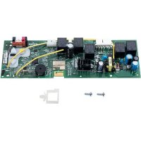
Light Lens End Panel Quick-Connect Terminals To insert or remove the wires from the terminal, push in the tab with a screwdriver tip. Motor Assembly Travel Module Wire Harness End Panel Logic Board Wire Harnesses Tabs Cover
text_image
BELT - Trolley Type A BELT - Trolley Type B Inner Trolley 1-1/4" (3.18 cm) Outer Trolley 1-1/4" (3.18 cm)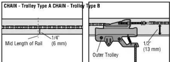
text_image
CHAIN - Trolley Type A CHAIN - Trolley Type B Mid Length of Rail 1/4" (6 mm) Outer Trolley 1/2" (13 mm)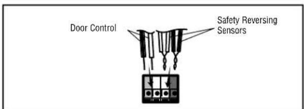
text_image
Door Control Safety Reversing SensorsADJUSTMENTS
PROGRAM THE TRAVEL
Your garage door opener is designed with electronic controls to make setup and adjustments easy. The adjustments allow you to program where the door will stop in the open (UP) and close (DOWN) position. The electronic controls sense the amount of force required to open and close the door. The force is adjusted automatically when you program the travel and cannot be changed.
text_image
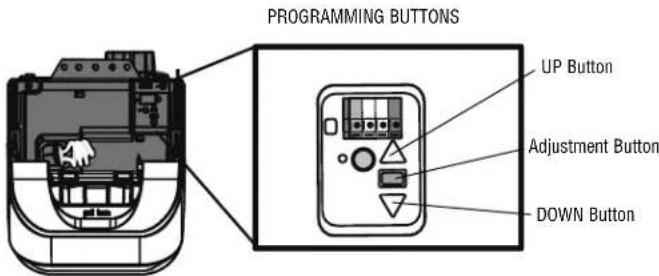
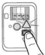
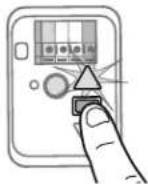
PROGRAMMING BUTTONS UP Button Adjustment Button DOWN ButtonSetting the UP position:
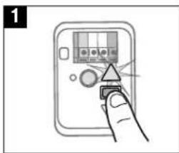
- Press and hold the Adjustment Button until the UP Button begins to flash and/or a beep is heard.
- Press and hold the UP Button until the door is in the desired UP position.
NOTE: The UP and DOWN Buttons can be used to move the door up and down as needed. - Once the door is in the desired UP position press and release the Adjustment Button. The garage door opener lights will flash twice and the DOWN Button will begin to flash.
Setting the DOWN position:
- Press and hold the DOWN Button until the door is in the desired DOWN position. NOTE: The UP and DOWN Buttons can be used to move the door up and down as needed.
- Once the door is in the desired DOWN position press and release the Adjustment Button. The garage door opener lights will flash twice and the UP Button will begin to flash.
- Press and release the UP Button. When the door travels to the programmed UP position, the DOWN Button will begin to flash.
- Press and release the DOWN Button. The door will travel to the programmed DOWN position. Programming is complete.
* If the garage door opener lights are flashing 5 times during the steps for Program the Travel, the programming has timed out. If the garage door opener lights are flashing 10 times during the steps for Program the Travel, the safety reversing sensors are misaligned or obstructed (refer to owner's manual). When the sensors are aligned and unobstructed, cycle the door through a complete up and down cycle using the remote control or the UP and DOWN buttons. Programming is complete. If you are unable to operate the door up and down, repeat the steps for Programming the Travel.
WARNING
Without a properly installed safety reversal system, persons (particularly small children) could be SERIOUSLY INJURED or KILLED by a closing garage door.
- Safety reversal system MUST be tested every month.
- After ANY adjustments are made, the safety reversal system MUST be tested. Door MUST reverse on contact with 1-1/2" (3.8 cm) high object (or 2x4 laid fl at) on floor.
CAUTION
To prevent damage to vehicles, be sure fully open door provides adequate clearance.
text_image
1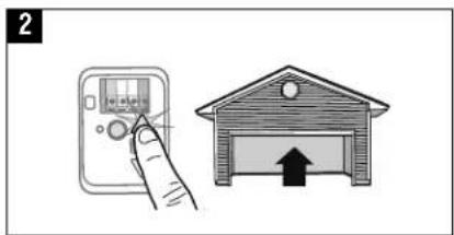
text_image
2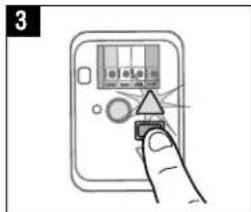
text_image
3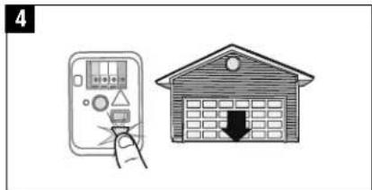
text_image
4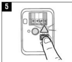
text_image
5
text_image
6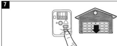
text_image
7ADJUSTMENTS
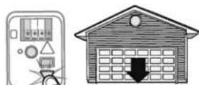
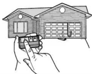
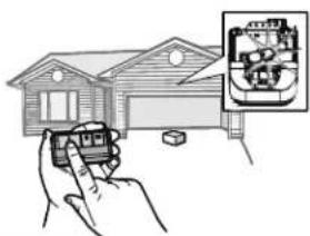
- With the door fully open, place a 1-1/2 inch (3.8 cm) board (or a 2x4 laid flat) on the floor, centered under the garage door.
- Press the remote control push button to close the door. The door MUST reverse when it makes contact with the board.
If the door stops and does not reverse on the obstruction, the travel needs to be adjusted (refer to Program the Travel).
Repeat the test. When the door reverses upon contact with the 1-1/2 inch (3.8 cm) board, remove the board and open/close the door 3 or 4 times to test the adjustment.
If the test continues to fail, call a trained door systems technician.
WARNING
Without a properly installed safety reversal system, persons (particularly small children) could be SERIOUSLY INJURED or KILLED by a closing garage door.
- Safety reversal system MUST be tested every month.
- After ANY adjustments are made, the safety reversal system MUST be tested. Door MUST reverse on contact with 1-1/2" high (3.8 cm) object (or 2x4 laid fl at) on the floor.
1
natural_image
Line drawing of a two-story house with a garage and roof, no text or symbols present2

natural_image
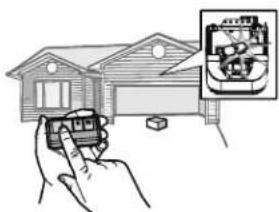
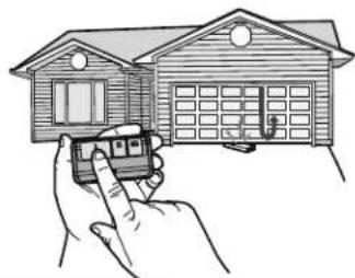
Line drawing of a hand holding a small car model next to a two-story house (no text or symbols)TEST THE PROTECTOR SYSTEM®
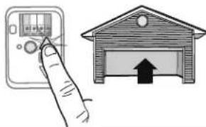
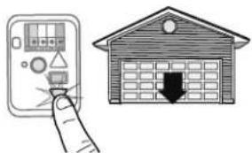
- Open the door. Place an obstruction in the path of the door.
- Press the remote control push button to close the door. The door will not move more than an inch (2.5 cm), and the garage door opener lights will flash 10 times.
The garage door opener will not close from a remote control if the LED in either safety reversing sensor is off (alerting you to the fact that the sensor is misaligned or obstructed).
If the garage door opener closes the door when the safety reversing sensor is obstructed (and the sensors are no more than 6 inches [15 cm] above the floor), call for a trained door systems technician.
WARNING
Without a properly installed safety reversing sensor, persons (particularly small children) could be SERIOUSLY INJURED or KILLED by a closing garage door.
1
natural_image
Simple line drawing of a two-story house with a garage and parked space (no text or symbols)2
natural_image
Illustration of a hand holding a small car with an inset showing internal components (no text or symbols)natural_image
Illustration showing a hand interacting with a control panel and a garage with an upward arrow (no text or symbols)3
4
5
6
natural_image
Illustration showing a hand pointing at a control panel next to a house with an upward arrow (no text or symbols)7
natural_image
Illustration of a hand interacting with an electronic device and a house-shaped door (no text or symbols)RÉGLAGES
ESSAI DU SYSTÈME D'INVERSION DE SÉCURITÉ
natural_image
Line drawing of a two-story house with a garage and parked door (no text or symbols)2
natural_image
Illustration of a hand holding a car with a door, next to a two-story house (no text or symbols)ESSAI DU SYSTÉME PROTECTOR®
natural_image
Simple line drawing of a two-story house with a garage and parked space (no text or symbols)2
natural_image
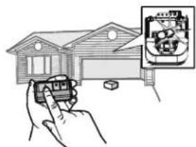
Illustration of a hand holding a small device next to a house, with an inset showing a close-up of a mechanical component (no text or symbols present)natural_image
Hand holding a device with a triangular indicator symbol (no text or labels visible)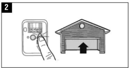
text_image
2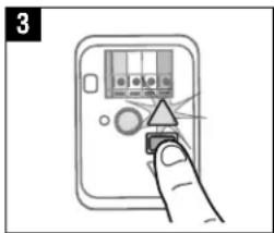
text_image
3
text_image
4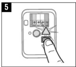
text_image
5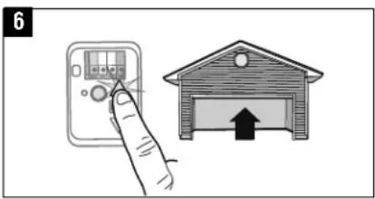
natural_image
Illustration showing a hand interacting with an electronic device next to a house outline (no text or symbols)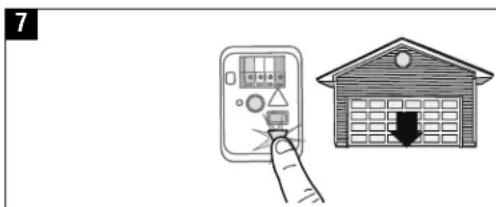
text_image
7AJUSTES
natural_image
Line drawing of a two-story house with a garage and windows (no text or symbols)2
natural_image
Illustration of a hand holding a small car near a two-story house (no text or symbols)PRUEBA DEL PROTECTOR SYSTEM®
natural_image
Line drawing of a two-story house with a garage and parked space (no text or symbols)2