
Control ECOWATT - Electric regulator Soler & Palau - Free user manual and instructions
Find the device manual for free Control ECOWATT Soler & Palau in PDF.
| Brand | Soler & Palau |
| Model | Control ECOWATT |
| Product type | Electrical regulator for ventilation |
| Available versions | AC/DC (0-10V output for DC motors) and AC/4A (voltage output for single-phase motors up to 4A) |
| Power supply AC/DC | 90-260 VAC, 50/60 Hz |
| Power supply AC/4A | 230 VAC + ground, 50 Hz |
| Operating modes | Proportional Integral (PI), Proportional, Mini-Maxi |
| Analog inputs | 3 inputs (0-10V / 4-20mA) for pressure, humidity, CO2, temperature sensors |
| Digital inputs | 3 contact inputs (NO/NC) for Mini-Maxi mode |
| Outputs | 1 analog output 0-10V (AC/DC) or motor voltage output (AC/4A); slave output 0-10V; alarm relay |
| Display | Digital screen with measured and set values |
| Dimensions (W x H x D) | 165 x 220 x 100 mm |
| Weight | Approximately 0.8 kg (estimate) |
| Protection rating | IP55 |
| Enclosure material | ABS V0, color RAL 7035 |
| Operating temperature range | -10°C to +50°C |
| Operating relative humidity | 30 to 95% non-condensing |
| Maintenance | No specific maintenance; regularly check condition and tightness of connections |
| Safety | Installation and interventions by a professional electrician; disconnect power before any intervention; insulation class I |
| Standards | Compliant with European directives, CE marking |
| Spare parts and reparability | No specific spare parts; repair by a qualified professional |
Frequently Asked Questions - Control ECOWATT Soler & Palau
User questions about Control ECOWATT Soler & Palau
0 question about this device. Answer the ones you know or ask your own.
Ask a new question about this device
Download the instructions for your Electric regulator in PDF format for free! Find your manual Control ECOWATT - Soler & Palau and take your electronic device back in hand. On this page are published all the documents necessary for the use of your device. Control ECOWATT by Soler & Palau.
USER MANUAL Control ECOWATT Soler & Palau
| SI: 50% | PR-OUT: 40% |
| PI: 70% |
| S2: 1200 | PR-OUT: 80% |
| P2: 1000 PPM |
| S3: 25 | PR-OUT: 100% |
| P3: 220C |
S1, S2 o S3:
| S1: 150 | PR-OUT: 50% |
| P1: 150 Pa |
line
| Position | Value | |---|---| | Rango de velocidades | Min output | | Salida | Max output | | P | Min output | | Entrada | Max output || Sl: 60 Set Point: 150 | PR-OUT: 80% |
| Sl: 60 Range: 50 | PR-OUT: 80% |
| Sl: 60 | PR-OUT: 80% |
| Kp: 1000 |
| Sl: 60 | PR-OUT: 80% |
| Ki: 100 |
Funcionalidad "PROPORTIONAL"
| Sl: 60 | PR-OUT: 80% |
| IN1 Type: %(V) |
| S1: 60 | PR-OUT: 80% |
| INI RANGE: 100% |
| Sl: 60 | PR-OUT: 80% |
| INl SET: 70% |
| SI: 60 | PR-OUT: 80% |
| SI ALARM: 90% |
SI: 60 PR-OUT: 80%
MIN-OUTPUT: 10%
SI: 60 PR-OUT: 80%
MAX-OUTPUT: 100%
Sl: 60 PR-OUT: 80%
Salve-OUT: 100%
SI: 60 PR-OUT: 80%
Hall pulses: 0
natural_image
Pure electrical circuit lines without any symbolsThe range includes three models differentiated by input and motor output:
- CONTROL ECOWATT AC/DC: model with AC input and 0-10V analogical output for DC motors or frequency converters (Fig.1).
- CONTROL ECOWATT AC/4A: model with single-phase AC input and voltage output for single-phase motors up to 4A. With this model, 0-10V analogical outputs for DC motors or frequency converters are also active (Fig.2).
Each model has three function modes:
- Proportional Integral control (PI) with analogical input (0-10V / 4-20mA)
- Control with three analogical inputs (0-10V / 4-20mA)
- Control with three digital inputs
CONTROL ECOWATT AC/DC incorporates an analogical output and can control both master and slave fans.
INSTALLATION
Workshop assembly by authorised technicians
Fix to vertical wall with cable glands facing down, leave space around the fixture for evacuation of thermal losses.
POWER SUPPLY
CONTROL ECOWATT AC/DC: 90 - 260VAC - 50/60Hz
CONTROL ECOWATT AC/4A: 230VAC + earth - 50Hz
FRONT PANEL AND FUNCTION SETTINGS
Digital display where the first line shows input values measured by sensors and output values given as a % of the range of speeds.
The lower line indicates adjustment values (if no adjustments are made, the factory settings are shown).
| S1: 50% | PR-OUT | : 40% |
| P1: 70% |
| S2: 1200% | PR-OUT: 90% |
| P2: 1000 PPM |
| S3: 25% | PR-OUT | : 100% |
| P3: 22°C |
S1, S2 or S3:
Values measured by the sensors
- S1 relative humidity level in HR% (signal 0-10V)
- S2 concentration in PPM of CO2 (signal 4-20mA)
- S3 temperature in °C (signal 0-10V)
PR-OUT:
-% of 0-10V output for CONTROL ECOWATT AC/DC
- % of range of voltage adjustment for AC/4A CONTROL ECOWATT
P1, P2 or P3:
Settings at the average point of the selected range of functioning adjusted to the premises where the sensor is installed..
Four adjustment keys:
- ▲ and ▼ keys for changing the menus
-
- and + keys for changing the settings
LED indicating input signal for sensors S1, S2 and S3
LED indicating output signal or output voltage level (according to model)
Green LED "POWER ON" that indicates that the CONTROL ECOWATT is switched on.
Red LED "ERROR" that indicates a CONTROL ECOWATT function error.
SETTINGS
All models in the CONTROL ECOWATT range have three function modes:
PI PROPORTIONAL INTEGRAL
PROPORTIONAL
MINI MAXI
Changing the function settings
- After switching on the CONTROL ECOWATT, press one of the four keys on the front panel (within 10s).
- Press the keys - o + to change function mode (factory setting: PROPORTIONAL INTEGRAL)
"PROPORTIONAL INTEGRAL" mode
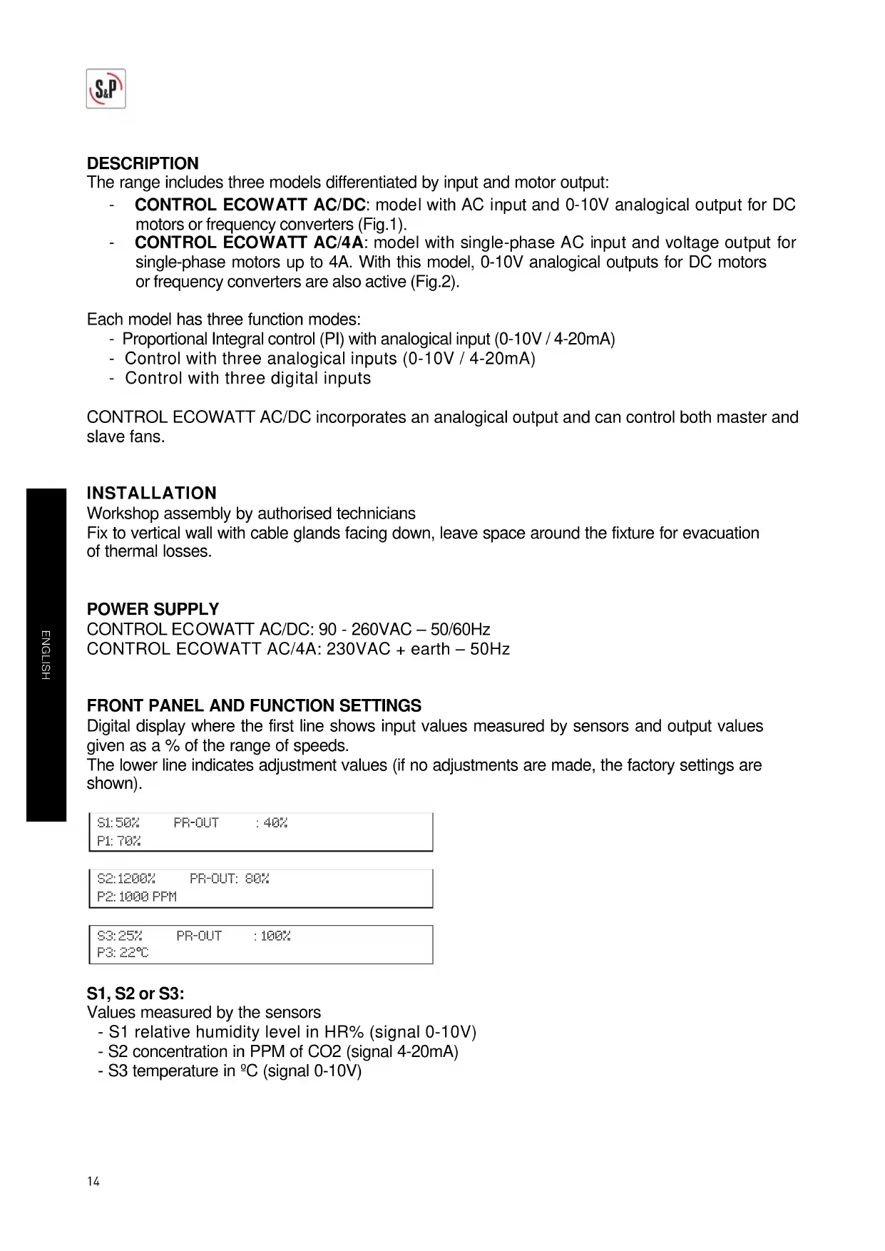
In this mode, the CONTROL ECOWATT is set up to function in a constant pressure system so a single input value is possible, the Pascal set point value that we want to maintain in the duct network. Only the S1 input may be used, connected to a TDP-type pressure transmitter.
S1:150% PR-OUT: 50% P1:150 Pa
line
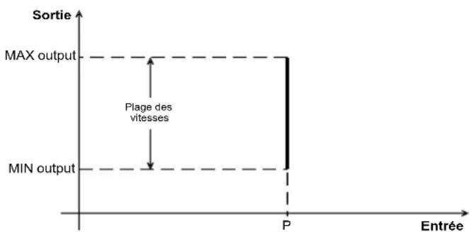
| Input | Output | |-------|--------| | P | MAX | | P | MIN |To change the set point and the variables set in factory:
- Press any of the 4 keys on the front panel.
- The words "Set Point" appear on the display. Use the keys - or + to change setting (factory setting: 150Pa)
Sl: 60 PR-OUT: 80%
Set Point: 150
- Press the key ▲ to move to the next parameter: "Range". This parameter allows entry to the bottom of the pressure sensor scale. Use the keys ▼ or + to change setting (factory setting: 0 – 300Pa)
S1: 60 PR-OUT: 80%
Range: 0-50
- Press the key ▲ to move to the next parameter: "Kp". This parameter allows modification of motor response by means of changes in network pressure. It is advisable to not change the settings. Use the keys - or + to change setting (factory setting: 1000)
Sl: 60 PR-OUT: 80%
Kp: 1000
- Press the key ▲ to move to the next parameter: "Ki". This parameter allows modification of motor response by means of changes in network pressure. It is advisable to not change the settings. Use the keys - or + to change setting (factory setting: 100)
Sl: 60 PR-OUT: 80%
Ki: 100
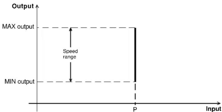
"PROPORTIONAL" mode
In this mode, the CONTROL ECOWATT is set up to work with one, two or three analogical inputs (J6, J7 or J8), 4-20mA or 0-10V. The CONTROL ECOWATT functions in accordance with the parameter of maximum demand. The sensors are connected in the inputs S1(J6), S2(J7) and S3(J8). Depending on the type of sensor (4-20mA or 0-10V) set the micro switch fitted in the circuit board to "mA" or "V".
line
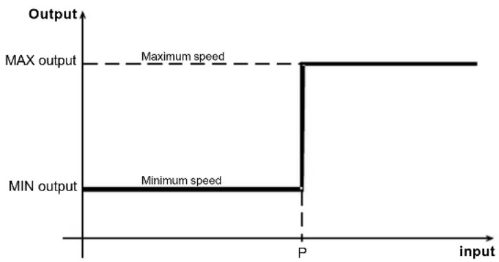
| Input Level | Output | | ----------- | ------ | | IN_min | MIN output | | P | Speed range | | IN_max | MAX output |To change input settings from factory settings:
- Press any of the 4 keys on the front panel.
- "IN1 Type" appears on the display. This parameter allows the selection of the measure unit for the channel 1 (sensor 1). The admitted measure units are:
- “OFF” to inactivate the channel when any sensor is connected.
o “%(V)” relative humidity sensor (RH%) connected to channel 1 with 0-10Vdc output.
o “%(mA)” relative humidity sensor (RH%) connected to channel 1 with 4-20mA output.
o "CO2(V)" CO2 sensor (PPM) connected to channel 1 with 0-10Vdc output.
o “CO2(mA)” CO2 sensor (PPM) connected to channel 1 with 4-20mA output
o “TEMP(V)” Temperature sensor (°C) connected to channel 1 with 0-10Vdc output.
o “TEMP(mA)” Temperature sensor (°C) connected to channel 1 with 4-20mA output.
Factory setting for IN1 Type = %RH(V)
Sl: 60 PR-OUT: 80%
IN1 Type: %HR
- Press the key ▲ to move to the next parameter: "IN1 RANGE". This parameter allows entry the pressure sensor range. Use the keys - or + to change setting (factory setting: S1= 0-100 %HR)
S1: 60 PR-OUT: 80%
IN1 RANGE: 0-100%HR
- Press the key ▲ to move to the next parameter: "IN1 SET" This parameter allows setting the average value of the sensor range. Use the keys ■ or + to change setting (factory setting: 70%HR)
S1: 60 PR-OUT: 80%
IN1 SET: 70%HR
- Press the key ▲ to move to the next parameter: "IN (+/-)". This parameter allows adjustment of the width setting range of the sensor. Use the keys - or + to change setting (factory setting: 40%HR)
Sl: 60 PR-OUT: 80%
IN (+/-): 40
- Press the key ▲ to move to the next parameter: "S1 ALARM". This parameter allows an alarm message to be sent when the average sensor value reaches a set percentage of the average range value. (factory setting: 90%)
S1: 60 PR-OUT: 80%
S1 ALARM: 90%
- Press the key ▲ to move to the next sensor "IN2 Type" and follow the adjustment procedure of the first sensor
IN2 SET=1000PPM IN3 SET=27°C
IN2(+/-)=1000PPM IN3(+/-)=5°C
S2 ALARM=90%(PPM) S3 ALARM=90%(°C)
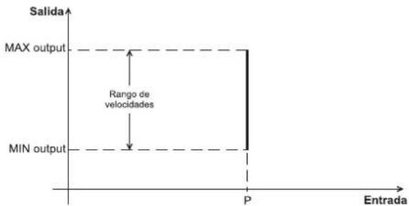
"MINI/MAXI" mode
In this mode, the CONTROL ECOWATT is set up to work with one, two or three contacts (J12, J13 and J14) of the normally open (NO) or normally closed (NC) type. The CONTROL ECOWATT functions in accordance with the first input that changes the setting and moves to maximum speed. The sensors or external contacts are connected in the inputs E1(J12), E2(J13) and E3(J14).
line
| input | Output | |-------|--------| | P | MAX output | | P | Minimum speed |To change contact setting
- Press any of the 4 keys on the front panel.
- "IN1 OFF (NO)" appears on the display. This parameter indicates that the contact is in its normal open position. Use keys - o + to change to NC (factory setting: NO)
- Press the key to ▲ move to the next inputs "IN2" and "IN3" and follow the same procedure for each input. (factory setting: EN2: OFF(NO) – EN3:OFF(NO)).
CONTROL ECOWATT resetting
- Press the keys - and + simultaneously during 5 seconds until "RESET" appears on the display, which allow to load all the factory setting values.
Restore defaults & Reset? NO
- Press the key + to confirm the resetting operation for all the variables.
Restore defaults & Reset? YES
This resetting operation needs a two-confirmation operation before to be achieved. Press the key ▲ to confirm the reset operation.
Changing output settings
To change the output settings that were set in the factory (applicable to the three modes):
- Press the keys simultaneously ▲ and ▼ until the first parameter "MIN-OUTPUT" appears on the display. This parameter allows adjustment of the minimum output setting to between 0 and 50%. (factory setting: 10%)
| Sl: 60 | PR-OUT: 80% |
| MIN-OUTPUT: 10% |
- Press the key ▲ to move to the next parameter: "MAX – OUTPUT". This parameter allows adjustment of the maximum output setting between 50 and 100%. (factory setting: 100%) – Output to terminals 10 and 11 of the J9 terminal.
| S1: 60 | PR-OUT: 80% |
| MAX-OUTPUT: 100% |
- Press the key ▲ to move to the next parameter: "Slave – OUT". This parameter allows adjustment of the maximum output setting between 50 and 150% of the second ventilator controlled by the CONTROL ECOWATT. (factory setting: 100%) – Output to terminal 12 and 13 of the J10 terminal.
| Sl: 60 | PR-OUT: 80% |
| Slave-OUT: 100% |
- Press the key ▲ to move to the next parameter: "Hall pulses". With this parameter the display displays the RPM speed of a motor fitted with a pulse per turn control. (factory setting: 0 – no effect) – Output to terminal 14 and 15 of the J11 terminal.
| Sl: 60 | PR-OUT: 80% |
| Hall pulses: 0 |
With the CONTROL ECOWATT AC/4A model, minimum voltage can be set between 80V and 150V, by means of the micro-switches (factory setting: 80V):
| 1 | 2 | 3 | Vmin |
| 0 | 0 | 0 | 80 |
| 0 | 0 | 1 | 90 |
| 0 | 1 | 0 | 100 |
| 0 | 1 | 1 | 110 |
| 1 | 0 | 0 | 120 |
| 1 | 0 | 1 | 130 |
| 1 | 1 | 0 | 140 |
| 1 | 1 | 1 | 150 |
ON=0
natural_image
Pure electrical circuit lines without any symbolsAdjustment values
Inputs:
| Sensor Unit Scale Set point Proportional band | ||||||||||
| Min. | Max. | Increase | Factory setting | Increase | Factory setting | Increase | Factory setting | Factory setting | ||
| Pressure | Pa | 0 | 2500 | 50 | 300 | 10 | 150 | --- | --- | --- |
| %HR | % | 0 | 100 | 10 | 100 | 5 | 70 | 5 | 40 | 40 |
| CO2 | ppm | 0 | 2000 | 100 | 2000 | 100 | 1000 | 100 | 1000 | 1000 |
| Temp. | °C | 0 | 50 | 5 | 50 | 1 | 22 | 1 | 5 | 5 |
Outputs:
| Unit | Min. | Max. | Increase | Factory settings | |
| Minimum speed (OUT MIN) | RPM | 0% | 50% | 5% | 10% |
| Maximum speed (OUT MAX) | RPM | 50% | 100% | 5% | 100% |
Alarms:
| Min. | Max. | Increase | Factory settings | ||
| S1 ALARM | 0% | 100% | 5% | 90% | 0,9 x 100 = 90%HR |
| S2 ALARM | 0% | 100% | 5% | 90% | 0,9 x 2000 = 1800 ppm |
| S3 ALARM | 0% | 100% | 5% | 90% | 0,9 x 50 = 45%HR |
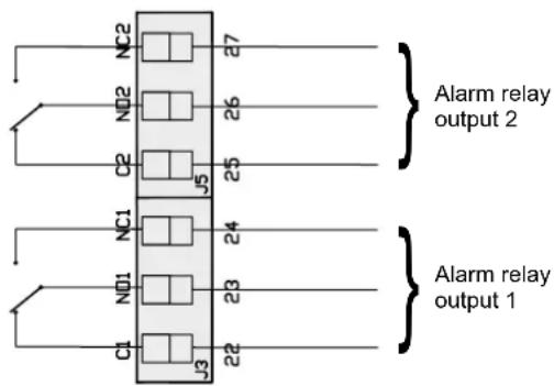
LED ERROR - OUTPUT RELAYS
CONTROL ECOWATT models include an LED "ERROR" on the front panel and in the circuit of the two relays RL1 and RL2. They have the following functions:
The function of relay 1 (J13) is Alarm or Error, together with the LED "ERROR".
Activation:
-
When all the sensors read 0 for 2s. The J13 relay is locked and the LED "ERROR" is lit. "S1 ERROR" appears on the display.
If this happens, check the sensor connections that show "error" on the display. -
In the PROPORTIONAL setting, when the alarm sensor limits are exceeded (S1 ALARM, S2 ALARM, S3 ALARM). The LED "ERROR" flashes twice. "S1 ALARM" appears on the display.
The function of relay 2 (J5), in the MIN-MAX setting, is to activate the high speed of a two-speed motor (2-windings single phase motor) when there is a change of input
text_image
NC2 7 NO2 26 C2 J5 25 NC1 24 NO1 23 C1 J3 22 Alarm relay output 2 Alarm relay output 1OTHER TECHNICAL SPECIFICATIONS:
Terminal connection capacity: 1 to 2,5 mm2
Electrical insulation class: Class 1
Box:
- Protection index: IP 55
- Material: ABS V0
- Colour: RAL 7035
- Supplied with two cable glands: 2 x PG21
- (Width x Height x Depth in mm) : 165 x 220 x 100
Storage: -20°C to +60°C; Relative humidity: 30 to 90%RH
Location:
- Temperature: -10°C to +50°C
- : 30 to 95% without condensation
Maintenance: Maintenance free, regularly check the connections and the atmospheric temperature to ensure that it is within the product limits.
Conformity: All CONTROL ECOWATT models comply with European Directives and standards and carry the EC conformity marking.
Connection to the electrical supply must be undertaken in accordance with current norms and standards on health and safety.
IMPORTANT! Installation, start-up, adjustment and all handling must be carried out by qualified professionals and in accordance with current standards on installation a health and safety. Before switching to low voltage, check that the input voltage corresponds to the data, as indicated on the product: connection to a different voltage could damage or destroy the machine. Disconnect the power supply before handling. Do not touch the low voltage parts. Danger of serious injury or death. Electrical connection that is not in accordance with these instructions and/or current installation standards invalidates the guarantee.
CONTROL ECOWAT AC/DC
text_image
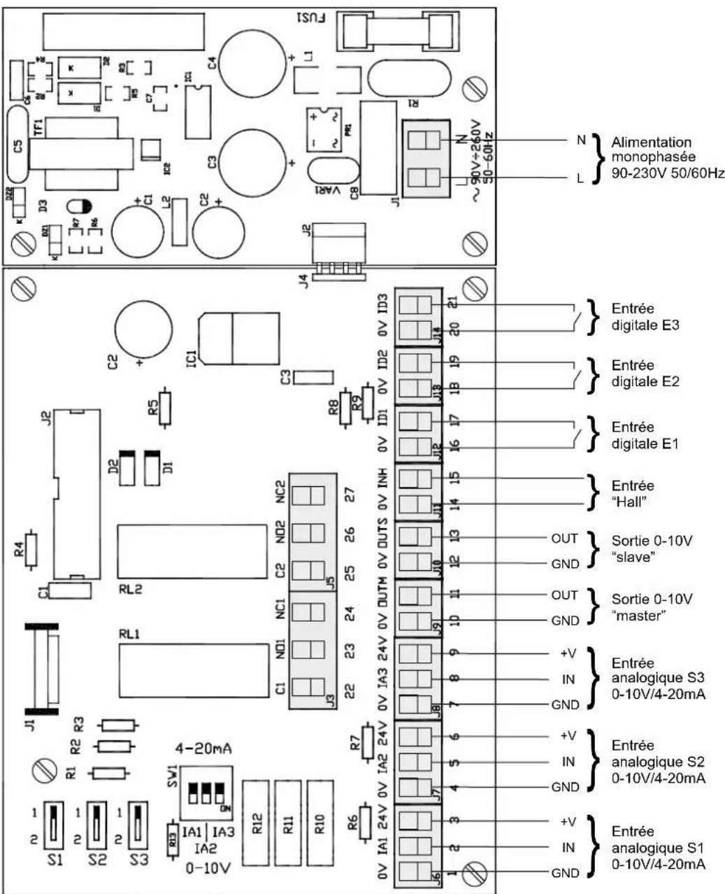
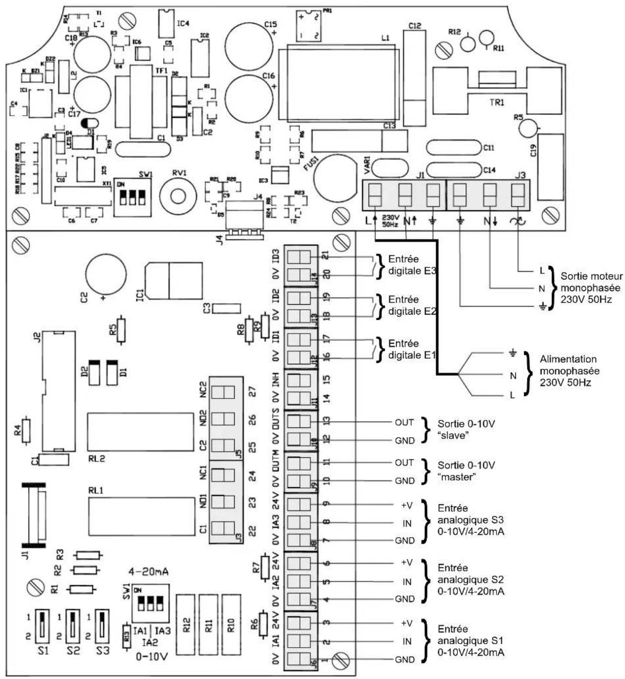
S1 2 1 S2 2 1 S3 2 1 R1 R2 R3 J1 C1 R4 J2 D2 D1 R5 C2 + IC1 C3 R6 R7 0V IA1 24V 0V IA2 24V 0V IA3 24V 0V OUTM 0V OUTS 0V INH 0V ID1 0V ID2 0V ID3 J6 1 2 3 4 5 6 7 8 9 10 11 12 13 14 15 16 17 18 19 20 21 GND IN +V GND IN +V GND IN +V GND IN + analogique S1 Antrée 0-10V/4-20mA Analogique S2 Antrée 0-10V/4-20mA Analogique S3 Antrée 0-10V/4-20mA Analogique S3 "master" Sortie 0-10V "slave" Entrée "Hall" Entrée digitale E1 Entrée digitale E2 Entrée digitale E3 Entrée L N Alimentation monophasée 90-230V 50/60Hz C5 TF1 TF2 TF3 TF4 TF5 TF6 TF7 TF8 TF9 TF10 TSI J K DZ1 D3 C5 R7 R6 R5 R3 R2 R1 + C1 L2 IC2 C3 + + C4 L1 + VAR1 PR1 J1 R ~90V+260V 50-60Hz L NFig.1
CONTROL ECOWAT AC/4A
text_image
R4 T1 L-J C18 R13 R3 IC6 C3 IC2 C15 + - PR1 L1 C12 R12 R11 K BZ1 K D22 U TF1 D2 C16 + - IC1 C3 C17 C1 S3 C2 R1 R2 R3 R4 R5 R6 R7 R8 R9 R10 R11 C13 C14 C19 C20 R17 R20 R25 C8 X11 DN SV1 RV1 R21 R20 C9 IC3 R24 R8 R23 T2 VAR1 J1 C14 J3 L 230V N ↑ N ↓ 230V 50Hz Sortie moteur monophasée 230V 50Hz L N Alimentation monophasée 230V 50Hz J4 C2 + IC1 C3 R8 R9 IDI 0V 0V INH 0V OUTM 0V OUTM 0V OUTM 0V OUTM 0V OUTM 0V OUTM 0V OUTM 0V OUTM 0V OUTM 0V OUTM 0V OUTM 0V OUTM 0V OUTM 0V OUTM 0V OUTM 0V OUTM 0V OUTM 0V OUTM 0V OUTM 0V OUTM 0V OUT M 0V OUTM 0V OUTM 0V OUTM 0V OUTM 0V OUTM 0V OUTM 0V OUTM 0V OUTM 0V OUTM 0V OUTM 0V OUTM 0V OUTM 0V OUTM 0V OUTM 0V OUTM 0V OUTM 0V OUTM 0V OUTM 0V OUTM 0V OUTFig.2
DESCRIPTION:
| S1: 50% | PR-OUT: 40% |
| P1: 70% |
| S2: 1,200 | PR-OUT: 80% |
| P2: 1,000 PPM |
| S3: 25 | PR-OUT: 100% |
| P3: 220C |
S1, S2 ou S3:
S1: 150 PR-OUT: 50% P1: 150 Pa
line
| Entry | Sortie | |-------|--------| | P | 1 | | P | MAX output | | P | MIN output | | P | Plage des vitesses |S1: 60 PR-OUT: 80%
Set Point: 150
SI: 60 PR-OUT: 80%
Range: 50
Sl: 60 PR-OUT: 80%
Kp: 1000
Sl: 60 PR-OUT: 80%
Ki: 100
Sl: 60 PR-OUT: 80%
IN1 Type: % (V)
SI: 60 PR-OUT: 80%
INI RANGE: 100%
SI: 60 PR-OUT: 80%
INI SET: 70%
SI: 60 PR-OUT: 80%
SI ALARM: 90%
IN2 SET=1000PPM IN3 SET=27°C
IN2(+/-)=1000PPM IN3(+/-)=5°C
S2 ALARM=90%(PPM) S3 ALARM=90%(°C)
Sl: 60 PR-OUT: 80%
MIN-OUTPUT: 10%
Sl: 60 PR-OUT: 80%
MAX-OUTPUT: 100%
Sl: 60 PR-OUT: 80%
Salve-OUT: 100%
Sl: 60 PR-OUT: 80%
Hall pulses: 0