
ILHB-ILHT ECOWATT - Household Fan Soler & Palau - Free user manual and instructions
Find the device manual for free ILHB-ILHT ECOWATT Soler & Palau in PDF.

| Product Type | Smoke Extract / Ventilation Fan |
| Model | ILHB-ILHT ECOWATT |
| Brand | Soler & Palau |
| Available Sizes | 355, 400, 450, 500, 630, 710 |
| Airflow Range | 500 to 24,000 m³/h |
| Motor Type | ECOWATT® high-efficiency motor, Class F |
| Power Supply | Single-phase 230V 50/60 Hz (sizes 355-450) or Three-phase 400V 50/60 Hz (sizes 500-710) |
| Control Modes | VAV (variable airflow), CAV (constant airflow), COP (constant pressure) |
| Control Options | Built-in potentiometer, external 0-10V signal, CVF/REB-ECOWATT remote, Modbus BMS |
| Smoke Extraction Certification | F400 120 (400°C for 120 min) per EN 12101-3 |
| Construction Material | Galvanised steel panels, aluminium section frame |
| Weight (approx.) | From 45 kg (size 355 MV) to 303 kg (size 710 CC insulated) |
| Mounting | Horizontal or vertical motor axis; multi-directional suction plenum |
| Safety Features | INTZ safety switch, thermal motor protection, fault relay, lockout before maintenance |
| Maintenance | Every 6 months: check turbine, controller, switch, grilles, ducts, fastenings |
| Warranty | 12 months parts only from date of manufacture |
| Operating Temperature | Ambient: -10°C to +45°C; Extracted air: up to 120°C continuous (400°C in smoke mode) |
| Relative Humidity | Max 95% non-condensing |
| Accessories (optional) | Flexible spool pieces, support arms, connecting flanges, vibration isolators, rain guard, double suction plenum, kitchen drain |
| Included | Fan unit with controller, INTZ safety switch (factory wired), mounting hardware |
Frequently Asked Questions - ILHB-ILHT ECOWATT Soler & Palau
User questions about ILHB-ILHT ECOWATT Soler & Palau
0 question about this device. Answer the ones you know or ask your own.
Ask a new question about this device
Download the instructions for your Household Fan in PDF format for free! Find your manual ILHB-ILHT ECOWATT - Soler & Palau and take your electronic device back in hand. On this page are published all the documents necessary for the use of your device. ILHB-ILHT ECOWATT by Soler & Palau.
USER MANUAL ILHB-ILHT ECOWATT Soler & Palau
natural_image
Exterior view of a stainless steel industrial machine with open doors and internal components (no visible text or symbols)
natural_image
3D rendering of an electronic device with cooling unit and mounting base (no visible text or symbols)INDICE
1. GENERAL....3
1.1 Disclaimers....3
1.2 Safety instructions 3
1.3 Storage.... 3
1.4 Warranty 4
2. PRODUCT PRESENTATION......4
3. INSTALLATION 5
3.1 Dimensions and weight (mm) 5
3.2 Summary charts of assembly and accessories 6
3.3 Accessories (dimensions in mm)....7
3.4 Handling 8
3.5 Casing assembly 9
4. ELECTRICAL CONNECTION 9
4.1 Preliminary precautions....9
4.2 Electrical characteristics.... 10
4.3 Wiring of INTZ safety switch.... 10
5. COMMISSIONING AND SETTING....11
5.1 Preliminary precautions....11
5.2 Controllers....11
5.3 Operation for smoke extraction 14
5.4 Ventilation fault indication 14
5.5 ILHB/T-ECOWATT Single-phase - VAV variable flow rate control 15
5.6 ILHB/T-ECOWATT Single-phase - CAV constant flow rate control.... 19
5.7 ILHB/T-ECOWATT Single-phase - COP constant pressure control 22
5.8 ILHB/T-ECOWATT 3-phases - VAV variable flow rate control 24
5.9 ILHB/T-ECOWATT 3-phases - CAV constant flow rate control....28
5.10 ILHB/T-ECOWATT 3-phases - COP constant pressure control 31
6. MAINTENANCE....34
7. WASTE MANAGEMENT 35
7.1 Treatment of Packagings and non dangerous wastes 35
7.2 Treatment of a Professional WEEE 35
1. GENERAL
1.1 Disclaimers
This product has been manufactured according to rigorous technical rules of safety in conformity with EC standards. The EC declaration may be downloaded from the Internet site (address given on the last page). Before installing and using this product, carefully read these instructions, which contain important indications for your safety and the user's safety during the installation, commissioning and maintenance of this product. Once the installation is achieved, keep this manual handy nearby the machine for future consultation.
This product must be installed (installation, connections, commissioning, maintenance) and all other interventions performed by a professional applying recognized good practice procedures, and respecting the standards and safety regulations in force. The installation must be made in accordance with the prescriptions indicated in the Electromagnetic Compatibility (EMC) and Low Voltage (LV) Directives.
We advise all people exposed to risks to scrupulously respect the accident prevention standards. The manufacturer may not be held liable for any human injury and/or material damage resulting from the non-respect of the safety instructions or from a change made on the product.
Smoke extract unit ILHB/T-ECOWATT are intended for smoke extraction and ventilation applications in residential buildings, tertiary buildings, industrial buildings and professional kitchens:
• Outdoor installation
• Environmental temperature range: -10ircC / +45ircC
- Max temperature of extracted air in permanent operation: 120ircC
• Relative humidity: max 95% non-condensing
• Atmosphere not potentially explosive
- Low salinity atmosphere, with no corrosive chemical agents
1.2 Safety instructions
- Wear suitable PPE (Personal Protective Equipment) before any intervention.
- Before installing the roof fan and its accessories, make sure that the support and the location are sufficiently resistant to withstand the unit's weight and the accessories, if any.
- Do not remove mesh grilles to access the impeller before cutting off the electric power supply with the safety switch.
- If the work is to be done inside the device, cut off the electric power supply with the main circuit breaker and make sure that nobody can accidentally switch it back on.
• Make sure that moving parts are stopped. - Make sure that the impeller is not accessible from connection tappings (connection duct or mesh protection).
Before starting, check the following points:
• Make sure that the device does not contain any foreign body.
- Make sure that all the components are attached to their original locations.
- Check manually that the impeller does not rub or is not blocked.
- Make sure that the mesh protection are in place.
• Make sure that the ground connection is connected.
1.3 Storage
The product must be stored protected from the weather, shocks and dirt due to splashings or splatterings of any kind during transport from the supplier to the end customer, and onto the worksite before installation.
1.4 Warranty
The equipment is warranted for twelve (12) months – Parts only – from date of manufacture.
S&P agrees to replace parts or the equipment whose operation is recognised defective by our departments, excluding all damages or penalties, such as operating losses, commercial prejudice, or other intangible or indirect losses.
Our warranty does not cover: (1) defects resulting from an abnormal use or an use not conforming to the recommendations indicated in our manuals; (2) defects observed following normal wear; (3) inc caused by negligence, lack of monitoring or maintenance; (4) defects due to the inappropriate installation of the devices or unsuitable pre-installation storage conditions.
In any case, S&P may not be held liable for transformed or repaired equipment even partially.
2. PRODUCT PRESENTATION
EC Certifi cate F400 -120 N° 1812-CPR-0040, according to European Standard EN 12101-3 Approved F400 120 (400°C 120 min)
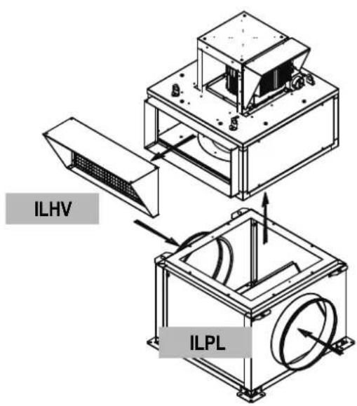
 | • ILHB/T-ECOWATT: complete unit with multi-directional suction plenum, with horizontal or vertical axis motor. |
 | • ILHB/T-ECOWATT: single ventilation unit, with horizontal or vertical axis motor. |
• 6 sizes : 355 / 400 / 450 / 500 / 630 / 710.
• Flowrates from 500 to 24 000 m 3 /h.
Construction
- Detachable galvanised steel sheet panels.
- Modular structure of aluminium sections.
- High performance galvanised steel reaction turbine, mounted by direct coupling with the motor.
Motor
- ECOWATT® motor, F class, 3 phases with remote IP55 controller :
-1 phase 230V 50/60Hz controller input for sizes 355 up to 450.
-3 phases 400V 50/60Hz controller input for sizes 500 up to 710.
• Thermal protection fitted within the controller.
Kitchen Option
The kitchen option includes a reinforced seal of the casing and a drain to dispose of wash water. The drain should be installed at the bottom of the casing to allow the wash water to be effectively discharged.
3. INSTALLATION
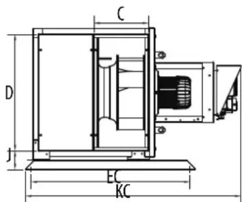
3.1 Dimensions and weight (mm)
ILHB/T-ECOWATT MV
Assembly with horizontal motor axis


Tipping risk during handling operations
Assembly with vertical motor axis

ILHB/T-ECOWATTCC
Assembly with horizontal motor axis

Assembly with vertical motor axis
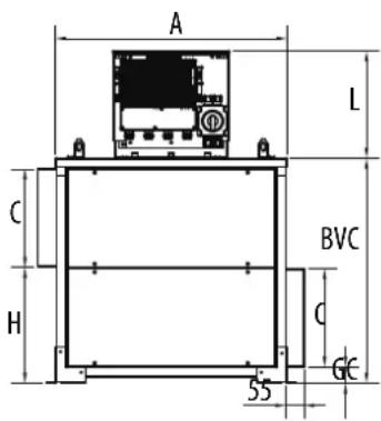

| Seize | A | BH | BV | BVC | C | D | E | EC | F | G | GC | H | J | K | KC | L | Weight MV (Kg) | Weight CC (Kg) | ||||
| NakedInsulated | NakedInsulated | |||||||||||||||||||||
| 355 | 627 | 695 | 327 | 645 | 263 | 559 | 606 | 790 | 660 | 31 | 50 | 315 | 102 | 826 | 1103 | 321 | 45 | 48 | 65 | 71 | ||
| 400 | 699 | 767 | 361 | 678 | 297 | 631 | 606 | 864 | 732 | 31 | 50 | 349 | 102 | 860 | 1170 | 321 | 56 | 60 | 79 | 87 | ||
| 450 | 779 | 847 | 392 | 738 | 326 | 711 | 606 | 990 | 812 | 31 | 50 | 378 | 102 | 892 | 1230 | 321 | 73 | 78 | 98 | 108 | ||
| 500 | 858 | 925 | 424 | 784 | 338 | 768 | 700 | 1039 | 890 | 42 | 62 | 402 | 112 | 954 | 1294 | 351 | 94 | 100 | 121 | 132 | ||
| 630 | 1066 | 1133 | 488 | 912 | 403 | 977 | 700 | 1183 | 1098 | 42 | 62 | 466 | 112 | 1018 | 1422 | 351 | 133 | 140 | 177 | 195 | ||
| 710 | 1194 | 1261 | 551 | 1032 | 462 | 1104 | 906 | 1325 | 1226 | 42 | 62 | 526 | 112 | 1070 | 1533 | 446 | 159 | 168 | 279 | 303 | ||
3.2 Summary charts of assembly and accessories

The TNHB/T-ECOWATT accessories on the diagram below can be used with the ILHB/T-ECOWATT MV with a vertical axis motor: (example below)
3.3 Accessories (dimensions in mm)
| Circular fl exible spool piece | Rectangular fl exible spool piece | |
ACOPEL F400 N ILAR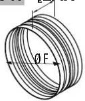 |  | |
ILSH | Standard support for horizontal axis motor:This support means that the casing can be attached fl oor with the motor in a horizontal position (horizontal axis). The 2 support arms are attached to the casing by the 4 M8 x 15 screws which are supplied, and the 4 stands are attached to the arms by the 16 self-drilling 4.8 x 12 screws which are supplied. | |
ILBR | Connecting fl angeThis connecting fl ange is attached to the plain fl ange at its 4 corners for the purpose of attaching a sheath. | |
ILBC | Circular connection to the MV suction, horizontal axis motor:This connection is used with the ILHB/T-ECOWATT MV for a sheath connection which does not have an upstand and which does not bear the weight of the casing. | |
ILRC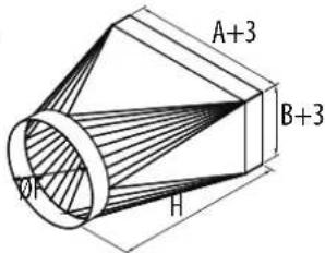 | Rigid circular connection | |
ISI  | 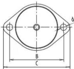 | Vibration isolating devices4 vibration isolating devices supplied with 4 screws to attach them to the casing. |
ILVV |  | Rain guard with bird guardThese guards are attached after the supplied plain fl ange has been detached from the casing. |
ILPL
Double suction plenum
To be bolted under the casing, without any accessory between the ILPL and the casing.
DRAIN (KITCHEN OPTION)
To install the drain at the bottom of the casing, make a 22 mm hole, position the drain with its seal and attach it with 2 3.5 x 19 screws (recommendation, screws not supplied).
Dimensions (mm) and weight (kg)
| ACOPEL F400 N / ILAR / ILBR / ILBC / ILRC / ISA-SLHT / ILVV / ILVH | ||||||||
| Model | A | B | C | D | E | ∅F | H | J |
| 355 | 559 | 263 | 197 | 194 | 160 | 400 | 670 | 80 |
| 400 | 631 | 297 | 216 | 213 | 160 | 450 | 670 | 80 |
| 450 | 711 | 326 | 233 | 234 | 160 | 500 | 670 | 80 |
| 500 | 768 | 338 | 240 | 249 | 160 | 560 | 670 | 80 |
| 630 | 977 | 403 | 278 | 305 | 160 | 710 | 670 | 80 |
| 710 | 1104 | 462 | 311 | 340 | 160 | 800 | 670 | 80 |
natural_image
Technical line drawing of a mechanical assembly with a crane lifting a component (no text or symbols present)To keep people safe or prevent damage to property use compliant handling equipment that is in a good condition.
The casing must be lifted at the 4 lifting lugs.
Use slings with a length that is at least double the height of the casing. Make sure that the slings do not rub against the motor cowl or the electrical accessories.
If in doubt, detach it to avoid any damage.
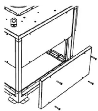
3.5 Casing assembly
The support surface that will support the base of the casing must be as flat at as possible (sealing frame or upstand supplied on demand). A seal of foam or similar material (not supplied) is recommended between the support surface and the base of the casing. A maximum incline of 2.5irc is tolerated between the motor axis and the vertical axis (see diagram below).

Make sure that the support is adapted to the weight of the whole machine and its various accessories. Attach the casing at the ∅20 holes provided for this purpose. You are advised to use a LL washer. Any screws that are not properly tightened may make noises and cause harmful vibrations. Once the machine has been correctly set up, make sure that the motor turbine is able to rotate freely without any friction or noise. Vibration isolating devices are available: ISA - ILHT.
natural_image
Technical line drawing of a mechanical assembly with no visible text or symbolsDetaching and re-assembling casing panels The smooth side panels are easy to detach by loosening their screws. They are repositioned in the same way.
4. ELECTRICAL CONNECTION
4.1 Preliminary precautions
Electrical connections must be set up by qualified staff. Electrical connections will be set up in accordance with applicable International, National and Local regulations. Do not forget the earthing connection.
In case of smoke extraction purpose, use high-temperature and protected against UV radiation cables. Please note that cables and electrical accessories must be dimensioned according to HF 384 European Standards (CENELEC). In this cases, no thermal protection device is permitted on the smoke extraction circuit.
Furthermore, the cables must be protected against any mechanical stress when they are routed if the connection is established on the terminal box of the motor or on the proximity switch of the casing. In case of comfort purpose, the motor must be protected by an adapted magnetothermal protection mechanism.
WARNING: use a voltage tester before you undertake any operation.
4.2 Electrical characteristics
| Model | P. Nom (kW) | I. Nom. (A) 230V | I. Nom. (A) 400V | INTZ | Electrical protection necessary |
| 355 | 0,70 3,05 | INTZ 1V15 10 A | |||
| 400 | 0,72 3,05 | INTZ 1V15 10 A | |||
| 450 | 1.24 5,40 | INTZ 1V15 10 A | |||
| 500 | 1,70 3,52 | INTZ 1V15 16 A | |||
| 630 | 3,16 6,99 | INTZ 1V15 16 A | |||
| 710 | 5,91 12,43 | INTZ 1V22 16 A |
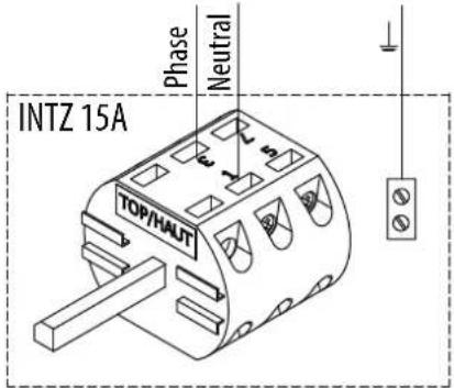
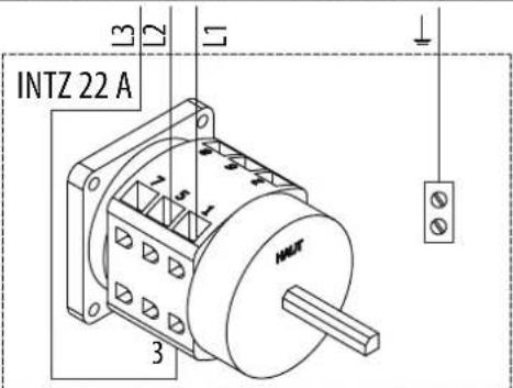
4.3 Wiring of INTZ safety switch
Safety switch delivered factory wired and mounted.
Note: the safety switch is sized to be used in smoke extract application for a 400V three-phases or 230V single-phase 50/60Hz power supply.
natural_image
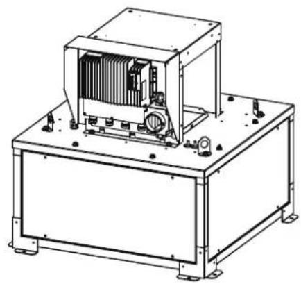
Technical line drawing of an industrial machine with cooling unit and mounting base (no text or symbols)Safety switch access : is located next to tl controller.
Wiring of version with INTZ safety switch 1V15
| Unit size 355 / 400 / 450with compacto controller | Unit size 500 / 630with Invento S controller |
 |  |
Wiring of version with INTZ safety switch 1V22
| Unit size 710 with Invento S controller | |
 | |
5. COMMISSIONING AND SETTING
5.1 Preliminary precautions
Before starting fan, make sure that the electric motor and impeller assembly rotate freely and that there is no object likely to be ejected by the turbine. The protection housings must be fastened to roof fan to prevent any accidental contact with rotating parts.
The machine should be attached to its support before power is applied.
Switch on just an instant to check the turbine's rotating direction.
WARNING: The impeller rotating direction must correspond to each speed in the direction indicated by the arrow on the product. A centrifugal backward fan unit with an impeller that does not rotate in the right direction still creates a flowrate and a low pressure in the duct. An incorrect rotating direction can lead to an abnormal overheating of the motor, resulting in its destruction and cancelling our manufacturer's warranty.
If the rotating direction is incorrect, cut off the electrical power supply, make sure no power is present, Contact after-sales service. Do not modify wirings, as this might seriously damages the unit.
While running, make sure that the motor's absorbed current is not more than 10% above the name plate indicated current.
Once the roof fan is installed and the tests successfully completed, present the main points of the operation and maintenance manual to the user, and explain:
• How to start up and shut down.
• How to change the operating modes.
Then hand over to the user the technical manual of the roof fan and the mounted accessories so that he can keep it handy to consult it at any time.
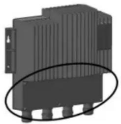
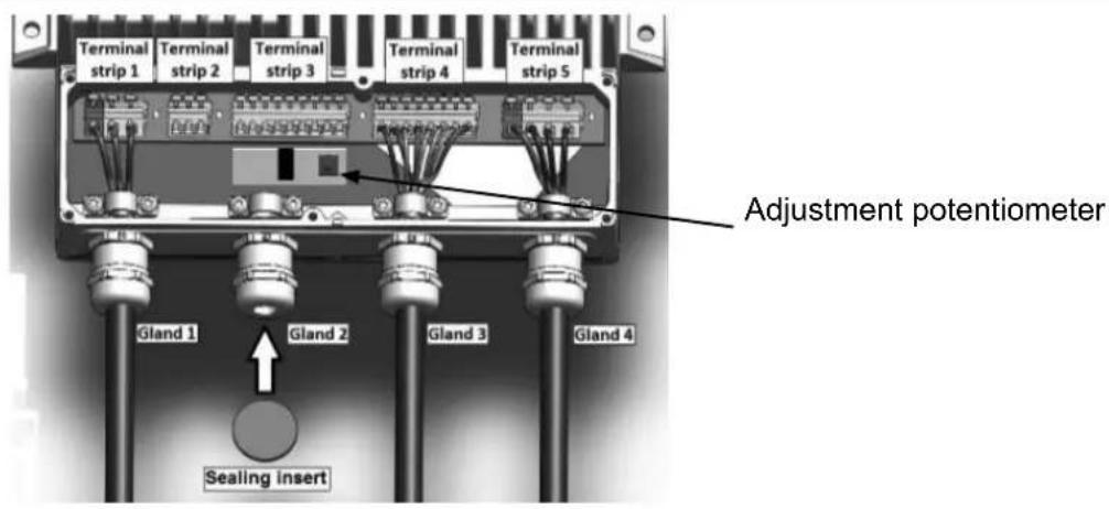
5.2 Controllers
The ECM motor controller controls this motor according to an adjusting potentiometer on the controller, an external 0-10V signal or a set point given by Modbus BMS.
The Modbus BMS connection, present as standard, allows you to adjust the flow rate set point or pressure, and to read the controller registers to find out the state of the roof fan.
5.2.1 Controller terminal block
natural_image
3D rendering of a black industrial electronic component with ventilation slots and mounting holes (no text or symbols visible)Unscrew the plate on the front of the controller (Torx T20 screwdriver).
5.2.2 Adjustment potentiometer
5.2.3 Fault correction
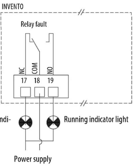
In the event of a fault, restarting operation after switching off the power for 5 minutes may allow the controller to reset. A fault relay allows us to identify the main causes of faults on the controller.
Connection of the relay:
For sizes 355/400/450: Controller - Terminals 4, 5, 6.
For sizes 500/630/710: Controller - Terminals 17, 18, 19.
Regardless of the principle of operation of the roof fan, the relay operates in the following manner:
| STATE OF THE UNIT | State of the relay** | Compacto | Invento |
| "Normal" operation (COP, CAV, VAV)=NO=5-6=18-19 | |||
| Supply cut off =NC=4-5=17-18 | |||
| On / Off switch open - the wheel is stationary but power is on to the controller. | NC | 4-5 | 17-18 |
| Loss of phases* - possibility that during a loss of phase the wheel continues to turn. | NC | 4-5 | 17-18 |
*If the control unit detects a fault more than once, notably a phase problem twice, the roof fan will not restart automatically. (**) NO.: normally open, NC: normally closed.
Switch off the power supply for 5 min and restart the roof fan. If the problem persists, it is possible to identify the nature of the problem in the registers of the Modbus. The controller operating manual is available for more information on www.solerpalau.com.
For sizes 355/400/450
The "Inputs" table allows you to read the following information:
| Register | Fault | Value | Description |
| 0 | Power on | 0-1 | 1 = Voltage too low to operate |
| 1 | Over voltage | 0-1 | 1 = Voltage too high to operate |
| 2 | IGBT over current | 0-1 | 1 = Over current protection triggered |
| 3 | Temperature | 0-1 | 1 = Thermal protection triggered, power reduced |
| 4 | Phase loss | 0-1 | 1 = loss of phase or motor synchronism |
| 5 | PFC over current | 0-1 | 1 = PFC protection (Power Factor Correction) FET triggered |
| 6 | CRC settings | 0-1 | 1 = Monitoring of parameters has failed (TBD) |
| 7 | Circuit fault | 0-1 | 1 = Error detected during checking of the internal circuits. |
| 8 | Motor fault | 0-1 | 1 = Abnormal motor behaviour |
| 9 | On temperature | 0-1 | 1 = Converter too hot to operate |
| 10 | I2R IGBT fault | 0-1 | 1 = IGBT programme protection triggered |
| 14 | Restart fault | 0-1 | 1 = Fault condition repeated more than once in a short time. The power converter must be restarted or reset. |
| Register | Fault Value Description | |
| 15=Fire mode=0-1=1 = Fire mode enabled | ||
| 16=Operation Active =0-1=1 = Operation Active | ||
| 17=Relay Active =0-1=1 = relay output enabled | ||
| 18=Awaiting shut-down=0-1=1 = The engine should stop, but is still running. | ||
| 24=Speed regulation=0-1=Speed regulator enabled | ||
| 25=Power regulation=0-1=Power limit regulator enabled | ||
| 26=Current regulation=0-1=Line current regulator enabled | ||
| 27 | Over modulation regulation 0-1 | Over modulation reached. The converter can no longer provide the voltage required for the motor. |
| 28=Regeneration regulation=0-1 | Motor in regeneration. Increased speed to prevent over voltage at the DC connection. | |
| 29=Phase current regulation=0-1=Motor phase RMS current limit | ||
| 30 | Synchronisation regulation 0-1=Motor still in synchronous mode | |
For sizes 500/630/710
The "Inputs" table allows you to read the following information:
| Register | Fault Value | Description |
| 0 | Power on | 0-1=1 = Voltage too low to operate |
| 1 | Over voltage | 0-1=1 = Voltage too high to operate |
| 2 | SW over current | 0-1=1 = current protection of the IGBT software |
| 3 | On temperature | 0-1=1 = Converter too hot to operate |
| 4 | Phase loss | 0-1=1 = Loss of phase or of main supply |
| 5 | Earth current fault | 0-1 1 = asymmetrical load (sum of all currents >3 A) |
| 6 | CRC settings | 0-1 1 = Monitoring of parameters has failed (TBD) |
| 7 | Driver fault | 0-1 1 = Transistor driver initialization fault |
| 8 | ADC fault | 0-1=1 = ADC conversion error |
| 9 | SPI communication fault=0-1=1 = No communication between the processors | |
| 10 | Reduction in power | 0-1 1 = Reduction in the power of the controller. |
| 11 | Stoppage of the reduction in power | 0-1=1 = Stop (motor stop) temperature of the controller reached |
| 12=HW over current | 0-1=1 = IGBT software current protection | |
| 13 | FLW enabled | 0-1 1 = Weakening of the active field |
| 14=System error | 0-1=1= Machine error | |
Refer to the controller operating manual (available on www.solerpalau.com).
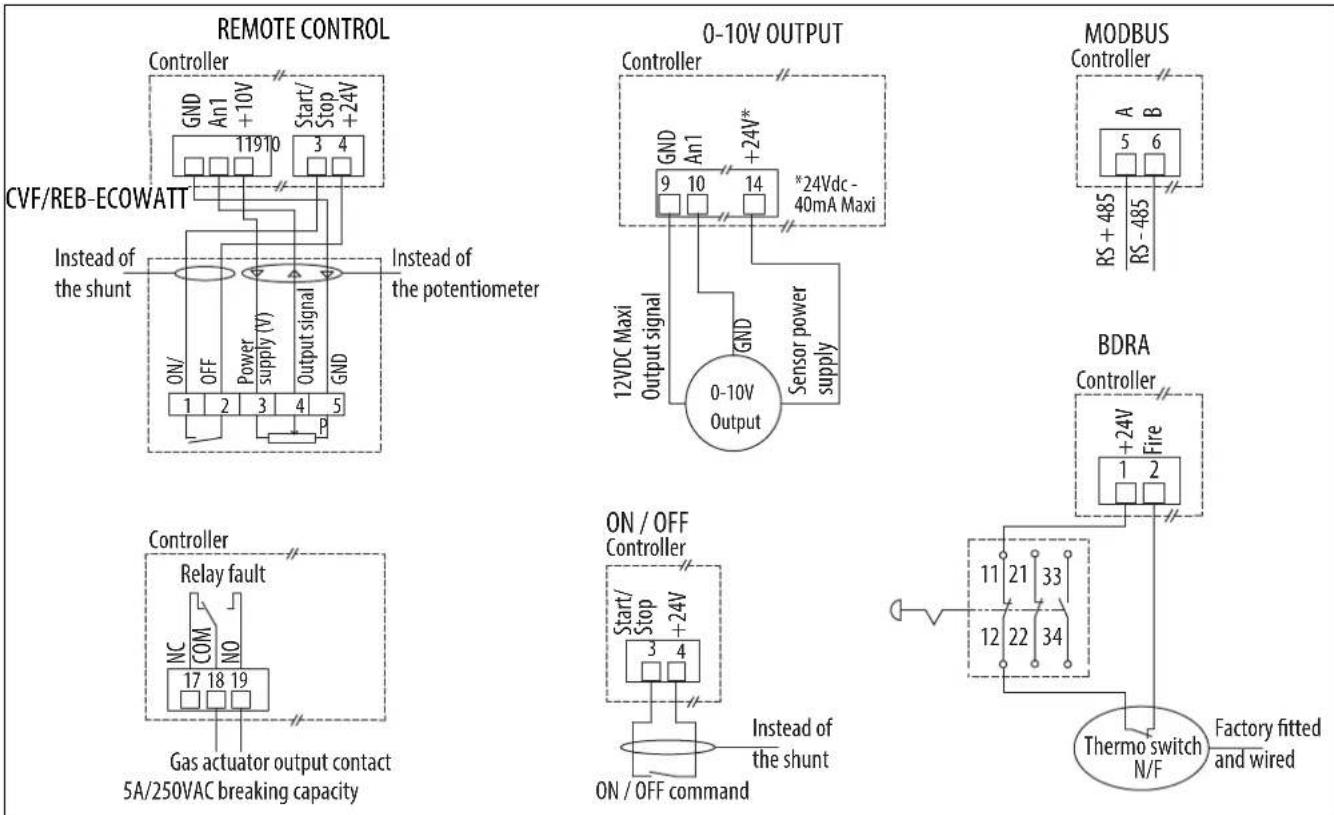
5.2.4 Modbus connection - Connection to a BMS
In the case of a connection to a BMS, the Modbus connection, present in standard, allows:
- ILHB/T-ECOWATT Single phase or 3-phase - Control of the VAV variable flow rate:
- On / Off
- Speed adjustment
- reading of registers (state of the casing).
- ILHB/T-ECOWATT Single phase or 3-phase - Adjustment to CAV constant flow rate:
- On / Off
- adjustment of the flow rate set point,
- reading of registers (state of the casing).
- ILHB/T-ECOWATT Single or 3-phase - Adjustment to COP constant pressure:
- On / Off
- adjustment of the pressure set point,
- reading of registers (state of the casing).
Refer to the corresponding paragraph below for the connection and the setting of your casing.
5.2.5 Default configuration settings
A USB converter with RS 485 is necessary for you to connect to the registers via a PC, as well as an interface of the same type as ModBus Doctor.
| Single-phase model* | 3-phase model* | |
| MODBUS address | 1 | 80 |
| Baut rate | 19200 | |
| START Bit | 1 | |
| STOP Bit | 1 | |
| Parity | NONE | |
* For additional information refer to the roof fan controller manual (available on www.solerpalau.com).
5.2.6 Input register table
The "Input Register" table allows you to read the following information:
| Register | Fonction | Resolution | Description |
| Single-phase model | |||
| 4 | Speed 1 rpm | ||
| 8 | Power 0,1 | W | |
| 9 | An1 input | 0,01 | V |
| 10 | An2 input | 0,01 | V |
| 11 | Pot input | 0,01 | V |
| Register | Fonction | Resolution | Description |
| 3-phase model | |||
| 0 | Speed 1 rpm | ||
| 2 | Power 1 | W | |
| 9 | An1 input | 0,01 | V |
| 10 | An2 input | 0,01 | V |
For all other information on the setting of Modbus, contact the After-Sales service department.
5.3 Operation for smoke extraction
The ILHB/T-ECOWATT is approved for extraction of hot gases and smoke in the event of a fire. This mode of operation is automatic and does not require any setting: In the case of extraction of gas at a temperature >200ircC , the roof fan will automatically switch to high speed with its internal thermal protections inhibited. The smoke extraction mode must be triggered manually with a BDRA type control unit.
The CAV/VAV/COP modes are no longer accepted.
5.4 Ventilation fault indication
Replaces the use of a PRESOSTATO DPS type pressure switch
| Ventilation fault | |
| ILHB/T-ECOWATT single phase | ILHB/T-ECOWATT 3-phase |
 |  |
| Stop ventilation inc light | Ventilation defect in cator light |
5.5 ILHB/T-ECOWATT Single-phase - VAV variable flow rate control
VAV - Slaving to an external signal
In variable speed operation, the controller pilots the speed of the roof fan linearly. The controller will vary the speed of the roof fan between 200 rpm (min. speed), and its maximum speed in proportion to the signal sent by the external sensor. If the display is present on the roof fan, it will show you the flow rate in m³/h.
The speed adjustment can be done in different ways:
• by the potentiometer integrated in the controller,
- by an ON/OFF + variation remote control (CVF or REB-ECOWATT),
• by an external 0-10V output,
- by a VRPZ voltage variator (allowing operation 0 / LS / HS with adjustable LS and HS),
• by flow rate control by Modbus BMS.
VAV - Regulation according to the deviation between the set point / external measurement
During operation at variable speed, the controller regulates the speed of the roof fan according to the set point-measurement deviation. The set point is adjusted with the potentiometer built into the controller or a CVF/REB-ECOWATT external control. If the display is present on the roof fan, it will show you the flow rate in m3/h .
Example of slaving and VAV regulation according to measurement of the outside temperature:
| VAV slaved according to measurement of the outside temperature | VAV with regulation according to the deviation between the set point / external measurement |
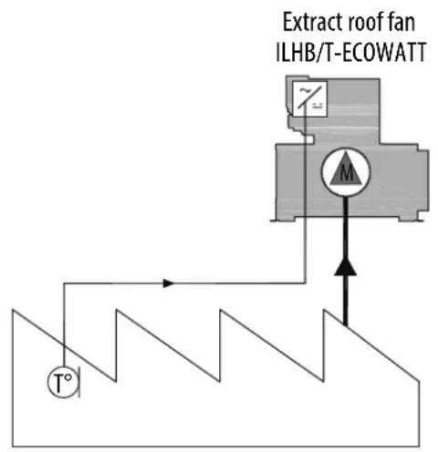 |  |
5.5.1 Connection
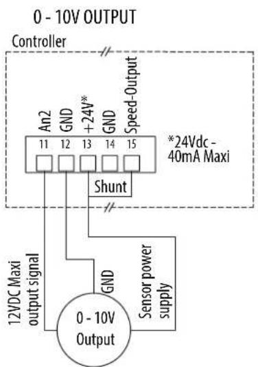
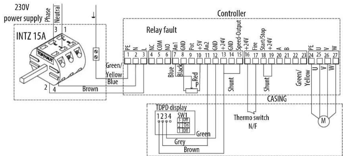
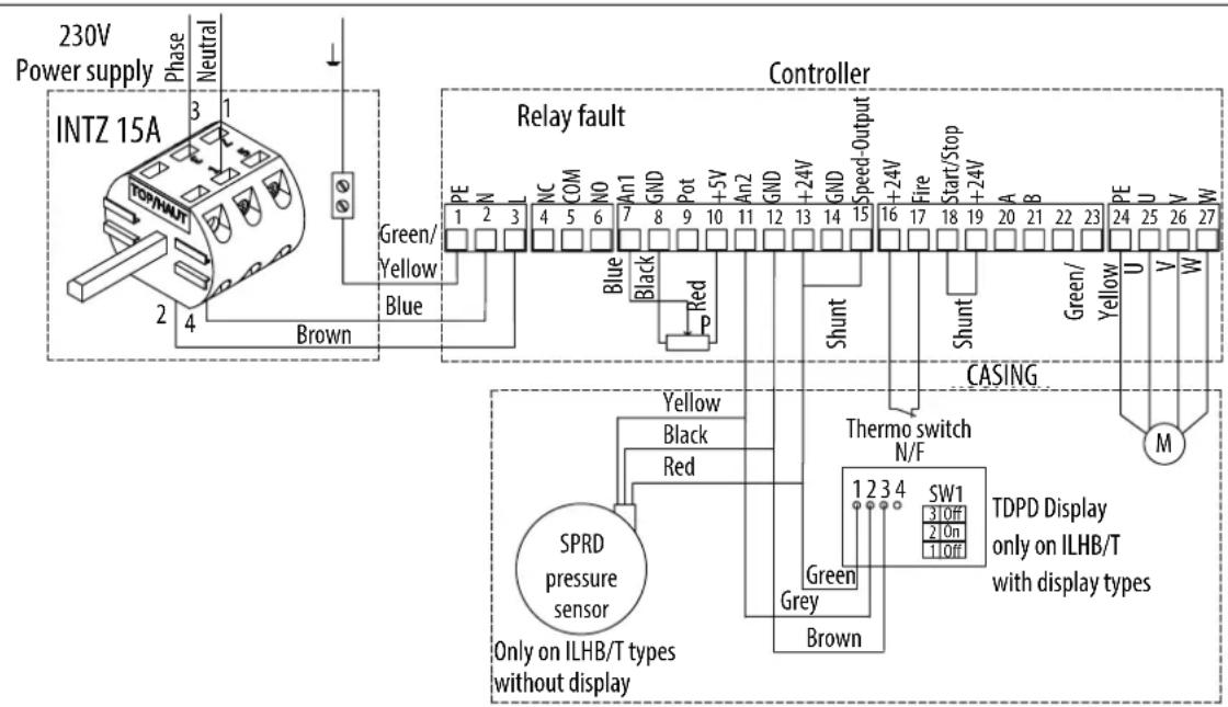
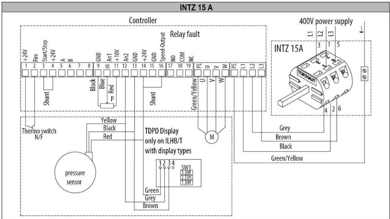
VAV type factory assembly and wiring, with or without display. Connection of the power supply to the INTZ switch to be done by the customer.
Wiring for accessories not supplied
Wiring for manual adjustment and slaving to an external signal
When the speed adjustment is done by the CVF/REB-ECOWATT type remote control, the 0-10V output or the Modbus BMS, the factory-fi tted potentiometer in the controller must be disconnected.
*0-10V output examples: temperature sensor, humidity sensor.
0-LS-HS installation diagram, with adjustable LS and HS
The LS and the HS are adjusted by a VRPZ voltage variator (accessory not supplied). 0-LS-HS choice with the VRPZ.
Wiring for regulation according to the deviation between the set point / external measurement

flowchart
graph TD
    A["Controller"] --> B["An1 7 GND +5V"]
    A --> C["Start/Stop 18 +24V"]
    D["CVF/REB-ECOWATT"] --> E["On/ OFF Power supply (V) Output signal"]
    F["Instead of the shunt"] --> E
    G["Instead of the potentiometer"] --> H["GND"]
    I["P"] --> J["Output signal"]
    K["Power supply (V)"] --> L["Ground"]
flowchart
graph TD
    A["0 - 10V OUTPUT"] --> B["Controller"]
    B --> C["An2 11"]
    B --> D["GND 12"]
    B --> E["+24V* 13"]
    B --> F["GND 14"]
    B --> G["Speed-Output 15"]
    B --> H["*24Vdc - 40mA Maxi"]
    H --> I["Shunt"]
    I --> J["12VDC Maxi output signal"]
    I --> K["GND"]
    K --> L["0 - 10V Output"]
    L --> M["Sensor power supply"]
5.5.2 Speed adjustment (unregulated VAV)
By potentiometer, or CVF/REB-ECOWATT type remote control.
By default the roof fan is set to its maximum speed, in bold in the table below.
The potentiometer in the controller allows you to change the speed of the turbine to adjust the flow rate.
The adjustment can be done with a CVF/REB-ECOWATT type remote control.
Correspondence table between the graduation of the internal potentiometer, the voltage applied on terminal 9 and the speed.
| Graduation potentiometer | Voltage (V) at terminal 9 | ILHB/T-ECOWATT 355 | ILHB/T-ECOWATT 400/450 |
| 0 0 200 rpm 200 rpm | |||
| 2 1 530 rpm 460 rpm | |||
| 4 2 850 rpm 720 rpm | |||
| 6 3 1 180 rpm 980 rpm | |||
| 8 4 1 500 rpm 1 240 rpm | |||
| 10 5 1 830 rpm 1 500 rpm | |||
For information: The flow rate is proportional to the speed of rotation.
Q _ v 2 = Q _ v 1 × ( N _ 2N _ 1) N is the speed of rotation.
By 0-10V output
Correspondence table between the voltage applied on terminal 7 and the speed.
| Voltage (V)at terminal 7 | ILHB/T-ECOWATT355 | ILHB/T-ECOWATT400/450 |
| 0 200 rpm 200 rpm | ||
| 2 530 rpm 460 rpm | ||
| 4 850 rpm 720 rpm | ||
| 6 | 1 180 rpm | 980 rpm |
| 8 | 1 500 rpm | 1 240 rpm |
| 10 | 1 830 rpm | 1 500 rpm |
Speed adjustment 0 / LS / HS (adjustable LS and HS)
The adjustment can be done with a VRPZ voltage variator.
The low speed and the high speed are adjusted with the VRPZ, see VRPZ operating instructions.
Speed adjustment by the Modbus BMS
The adjustment can be done with a Modbus BMS. To know the parameters of the Modbus connection, refer to § "5.2.4 Modbus connection - Connection to a BMS".
After you wired your Modbus Link:
Turn on the power to connect yourself to the controller. The fan wheel must be stopped.
| Steps | Register numbers | Value to be entered | |
| 1 - Access to Level 1 | 5 | 1 | |
| 2 - Change in the operating mode of the controller | 6 | 2 | |
| 3 - Saving of changes | 5 | 10000 | |
| 4 - Changing the set point | 0 | Between 1000 and 10,000 to set the desired speed of the roof fan, see the table below | |
| Fan stop | 0 | 0 | |
| Register set point 0 | ILHB/T-ECOWATT355 | ILHB/T-ECOWATT400/450 | |
| 1000 | 200 rpm | 200 rpm | |
| 2000 | 380 rpm | 345 rpm | |
| 3000 | 560 rpm | 490 rpm | |
| 4000 | 740 rpm | 630 rpm | |
| 5000 | 920 rpm | 780 rpm | |
| 6000 | 1 110 rpm | 920 rpm | |
| 7000 | 1 290 rpm | 1 070 rpm | |
| 8000 | 1 470 rpm | 1 210 rpm | |
| 9000 | 1 650 rpm | 1 360 rpm | |
| 10000 | 1 830 rpm | 1 500 rpm | |
5.6 ILHB/T-ECOWATT Single-phase - CAV constant flow rate control
During operation at constant flow rate, the controller regulates the speed of the roof fan to obtain the set point flow rate. A display installed under the cap indicates the flow rate measured in m/h. The flow rate set point can be adjusted by the potentiometer in the controller, by ON/OFF + variation remote control, by an external 0-10V output or by Modbus BMS.
5.6.1 Wiring
CAV type factory assembly and wiring. Connection of the power supply to the INTZ switch to be done by the customer.
Wiring for accessories not supplied
When the flow rate set point adjustment is given by the CVF/REB-ECOWATT type remote control or the 0-10V output, the factory-fi tted potentiometer in the controller must be disconnected.
When the speed set point setting is given by the MODBUS BMS the factory-fi tted potentiometer in the controller must be disconnected, as well as the shunt between terminals 13 and 15.
flowchart
graph TD
    subgraph_Remote_Control["REMOTE CONTROL"]
        A["Controller"] --> B["An1 7 GND +5V Start/Stop +24V"]
        B --> C["CVF/REB-ECOWATT"]
        C --> D["On/OFF Power supply (V) Output signal GND"]
        D --> E["Instead of the shunt"]
        E --> F["1 2 3 4 5 P"]
        F --> G["Output Signal"]
        H["0-10V OUTPUT"] --> I["Controller"]
        I --> J["An1 7 GND +24V* 13 *24Vdc - 40mA Maxi"]
        J --> K["Sensor power supply"]
        K --> L["0-10V Output"]
        M["MODBUS"] --> N["Controller"]
        N --> O["A 20 RS +485 B"]
        N --> P["B -485 RS"]
        Q["BDRA"] --> R["Controller"]
        R --> S["+24V Fire"]
        T["Factory fitted and wired"] --> U["Thermo switch N/F"]
    end

    subgraph_Control_Control["Control"]
        V["Controller"] --> W["Relay fault NC COM NO"]
        W --> X["Gas actuator output contact 5A/250VAC breaking capacity"]
        X --> Y["P"]
    end

    style Remote_Control fill:#f9f,stroke:#333
    style Remote_Control fill:#ccf,stroke:#333
    style Control_Control fill:#cfc,stroke:#333
    style Control_Control fill:#fcc,stroke:#333
    style Control_Control fill:#ffc,stroke:#333
    style Control_Control fill:#fcc,stroke:#333
    style Control_Control fill:#ffc,stroke:#333
    style Control_Control fill:#fcc,stroke:#333
    style Control_Control fill:#cff,stroke:#333
    style Control_Control fill:#ffc,stroke:#333
    style Control_Control fill:#ffc,stroke:#333
    style Control_Control fill:#ffc,stroke:#333
    style Control_Control fill:#ffc,stroke:#333
    style Control_Control fill:#ffc,stroke:#333
    style Control_Control fill:#ffc,stroke:#333
    style Control_Control fill:#ffc,stroke:#333
    style Control_Control fill:#ffc, stroke:#333
    style Control_Control fill:#ffc,stroke:#333
    style Control_Control fill:#ffc,stroke:#333
    style Control_Control fill:#ffc,stroke:#333
    style Control_Control fill:#ffc,stroke:#333
    style Control_Control fill:#ffc,stroke:#333
    style Control_Control fill:#ffc,stroke:#333
    style Control_Control fill:#ffc,stroke:#�33
    style Control_Control fill:#ffc,stroke:#333
    style Control_Control fill:#ffc,stroke:#333
    style Control_Control fill:#ffc,stroke:#333
    style Control_Control fill:#ffc,stroke:#333
    style Control_Control fill:#ffc,stroke:#333
5.6.2 Adjusting the flow rate set point,
By potentiometer, CVF/REB-ECOWATT type remote control or 0-10V output.
Adjustment of the flow rate set point by potentiometer, CVF/REB-ECOWATT type remote control or 0-10V output.
The potentiometer in the controller allows you to change the flow rate set point.
The display under the cap shows the calculated flow rate.
For Sizes 355 / 400 / 450 : the display shows m³/h.
| Graduation potentiometer | Flow rate (m3/h) | ||||
| 355 | 400 | 450 | |||
| 0 | 0 | 0 | |||
| 1 | 2040 | 3050 | 3340 | ||
| 2 | 2880 | 4320 | 4720 | ||
| 3 | 3530 | 5290 | 5780 | ||
| 4 | 4080 | 6100 | 6680 | ||
| 5 | N | / | A | ||
| Graduation potentiometer | Flow rate (m3/h) | ||||
| 355 | 400 | 450 | |||
| 0 | 6 | N/A | N/A | 8170 | |
| 7 | N/A | N/A | N/A | ||
| 8 | N/A | N/A | N/A | ||
| 9 | N/A | N/A | N/A | ||
| 10 | N/A | N/A | N/A | ||
| N/A : max. flow rate already reached | 7 | ||||
Note: After each adjustment wait 1 minute for the fan speed to stabilize.
By Modbus BMS
The flow rate set point can be given by a Modbus BMS set point. To find the settings of the Modbus connection, refer to § "5.2.4 Modbus connection - Connection to a BMS".
After you wired your Modbus link:
Turn on the power to connect yourself to the controller. The roof fan wheel must be stopped.
| Steps | Register numbers | Value to be entered | |
| 1 - Access to Level 1 | 5 | 1 | |
| 2 - Change in the operating mode of the controller | 6 | 9 | |
| 3 - Saving of changes | 5 | 10000 | |
| 4 - Changing the set point | 16 | Between 0 and 1,000 to defi ne the desired flow rate set point, see the table below | |
| Register set point 16 | ILHB/T-ECOWATT355 | ILHB/T-ECOWATT400 | ILHB/T-ECOWATT450 |
| 100 2 040 m | 3/h 3 050 m | 3/h 3 340 m | 3/h |
| 200 2 880 m | 3/h 4 320 m | 3/h 4 720 m | 3/h |
| 300 3 530 m | 3/h 5 290 m | 3/h 5 780 m | 3/h |
| 400 4 080 m | 3/h 6 100 m | 3/h 6 680 m | 3/h |
| 500 | N/A | N/A | 7 460 m3/h |
| 600 | N/A | N/A | 8 170 m3/h |
| 700 | N/A | N/A | N/A |
| 800 | N/A | N/A | N/A |
| 900 | N/A | N/A | N/A |
| 1000 | N/A | N/A | N/A |
For information: Calculation of the flow rate according to the set point
Q _ v = Kx 2 , 5 xsetpoint
| Size of ILHB/T-ECOWATT | Coeff. K |
| 355 | 129 |
| 400 | 193 |
| 450 | 211 |
5.7 ILHB/T-ECOWATT Single-phase - COP constant pressure control
During operation at constant pressure, the controller regulates the speed of the roof fan to obtain the set pressure. If the display is present on the roof fan, it will show you the pressure in Pa. The pressure set point can be adjusted by the potentiometer in the controller, by a CVF/REB-ECOWATT ON/OFF + variation remote control, by an external 0-10V output or by Modbus BMS.
5.7.1 Wiring
COP type factory assembly and wiring. Connection of the power supply to the INTZ switch to be done by the customer.
Wiring for accessories not supplied
When the pressure set point is given by the CVF/REB-ECOWATT type remote control or the 0-10V output, the factory-fi tted potentiometer in the controller must be disconnected.
When the speed set point is given by the MODBUS BMS the factory-fi tted potentiometer in the controller must be disconnected, as well as the shunt between terminals 13 and 15.


flowchart
graph TD
    A["0-10V Output Signal"] --> B["12VDC Maxi Output Signal"]
    B --> C["An1 7 GND"]
    B --> D["An1 8"]
    B --> E["+24V* 13"]
    C --> F["GND"]
    D --> F
    E --> F
    F --> G["Sensor power supply"]
    H["Controller"] --> I["*24Vdc - 40mA Maxi"]


flowchart
graph TD
    A["Thermo switch N/F"] --> B["+24V Fire"]
    B --> C["Controller 16 17"]
    C --> D["Factory fitted and wired"]
    D --> E["11 21 33"]
    D --> F["12 22 34"]
5.7.2 Adjusting the pressure set point
By potentiometer, CVF/REB ECOWATT type remote control or 0-10V output.
By default the roof fan is set to obtain the pressure in bold in the table.
The potentiometer in the controller allows you to change the pressure set point.
The set point can be given by a CVF/REB ECOWATT type remote control or a 0-10V output.
Correspondence table between the potentiometer graduation, the voltage applied on terminal 7 and the pressure set point.
Note: After each adjustment wait 1 minute for the fan speed to stabilize.
| Potentiometer graduation | Voltage (in V) at terminal 7 | Without display | Voltage (in V) at terminal 7 | With display* |
| 0 | 0 | 0 | ||
| 1 0,5 0 Pa 0,5 80 Pa | ||||
| 2 1 100 Pa 1 160 Pa | ||||
| 3 1,5 200 Pa 1,5 240 Pa | ||||
| 4 2 300 Pa 2 320 Pa | ||||
| 5 2,5 400 Pa 2,5 400 Pa | ||||
| 6 3 500 Pa 3 480 Pa | ||||
| 7 3,5 600 Pa 3,5 560 Pa | ||||
| 8 4 700 Pa 4 640 Pa | ||||
| 9 4,5 800 Pa 4,5 720 Pa | ||||
| 10 5** 800 Pa 5** 800 Pa |
*If the roof fan has a display, the display will show you the pressure measured at the roof fan plate (see diagram below).
**If 0-10V source, 5 to 10V: 800Pa.
By Modbus BMS
The pressure set point can be given by a Modbus BMS set point. To find the Modbus connection settings, refer to § "5.2.4 Modbus connection - Connection to a BMS".
After you have wired your Modbus link:
Turn on the power to connect yourself to the controller. The roof fan wheel must be stopped.
Modbus register table:
| Steps | Register numbers | Value to be entered |
| 1 - Access to Level 1 | 5 | 1 |
| 2 - Change in the operating mode of the controller | 6 | 9 |
| 3 - Saving of changes | 5 | 10000 |
| 4 - Changing the set point | 16 | Between 0 and 1000 to define the desired pressure set point, see the table below |
| Without display With display | |||||
| Register set point 16 | Pressure (Pa) | Register set point 16 | Pressure (Pa) | ||
| 100 100 100 160 | |||||
| 200 300 200 320 | |||||
| 300 500 300 480 | |||||
| 400 700 400 640 | |||||
| 450 800 500 800 | |||||
| 450 à 1000 800 600 960 | |||||
| 700 1 120 | |||||
| 800 1 280 | |||||
| 900 1 440 | |||||
| 1000 1 600 | |||||
5.8 ILHB/T-ECOWATT 3-phases - VAV variable flow rate control
VAV - Slaving to an external signal
In variable speed operation, the controller pilots the speed of the roof fan linearly. The controller will vary the speed of the roof fan between 200 rpm (min. speed), and its maximum speed in proportion to the signal sent by the external sensor. If the display is present on the roof fan, it will show you the flow rate in m³/h.
The speed adjustment can be done in different ways:
• control by a potentiometer in the controller,
• control by a CVF ON/OFF + variation remote control,
• control by an external 0-10V output,
- by a VRPZ voltage variator (allowing 0 / LS / HS operation with adjustable LS and HS),
• flow rate control by Modbus BMS.
VAV - Regulation according to the deviation between the set point / external measurement
During operation at variable speed, the controller regulates the speed of the roof fan according to the set point-measurement deviation. The set point is adjusted with the potentiometer built into the controller or a CVF/REB-ECOWATT type external control. If the display is present on the roof fan, it will show you the flow rate in m3/h .
Example of slaving and VAV regulation according to measurement of the outside temperature:
| VAV slaved according to the temperature sensor | VAV with regulation according to the deviation between the set point / external measurement |
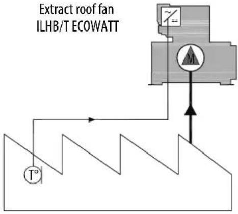 | 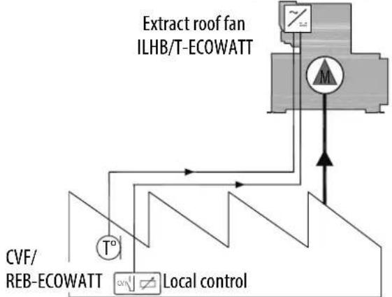 |
5.8.1 Wiring
VAV type factory assembly and wiring, with or without display. Connection of the power supply to the INTZ switch to be done by the customer.
INTZ 15 A
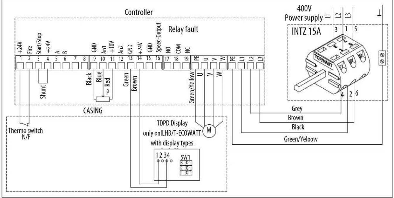
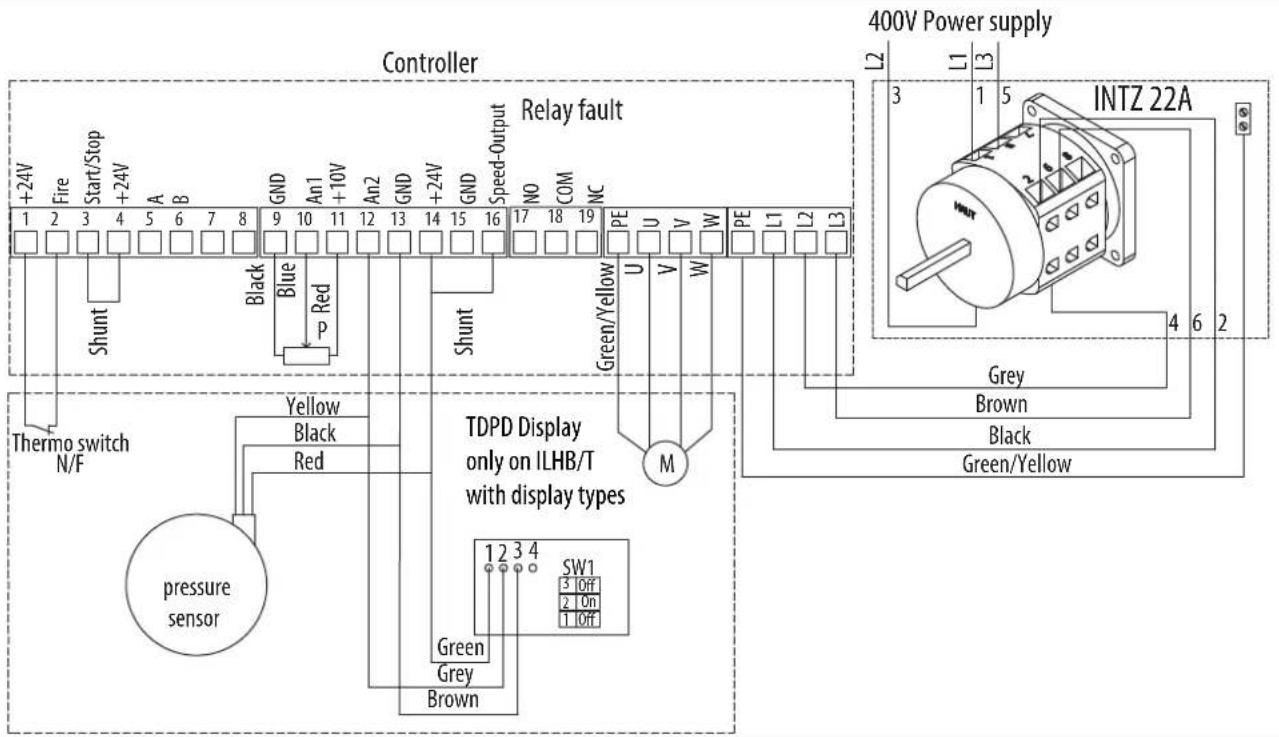
INTZ 22 A for ILHB/T-ECOWATT 710
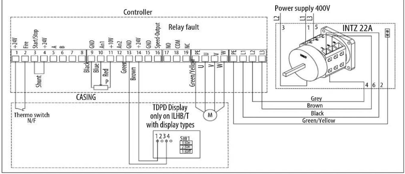
Wiring for accessories not supplied

Wiring for manual adjustment and slaving to an external signal.
When the speed set point adjustment is given by the CVF/REB-ECOWATT type remote control, the 0-10V output or the Modbus BMS, the factory-fi tted potentiometer in the controller must be disconnected.
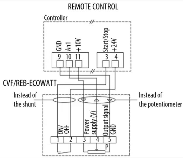
flowchart
graph TD
    A["Controller"] --> B["GND An1 +10V 11910"]
    A --> C["Start/Stop +24V 3 4"]
    D["CVF/REB-ECOWATT"] --> E["Power supply (V)"]
    F["Instead of the shunt"] --> G["OFF/ ON 1 2 3"]
    F --> H["Output signal P"]
    I["Instead of the potentiometer"] --> J["GND 5"]
    style A fill:#f9f,stroke:#333
    style D fill:#ccf,stroke:#333
    style F fill:#cfc,stroke:#333
    style I fill:#fcc,stroke:#333
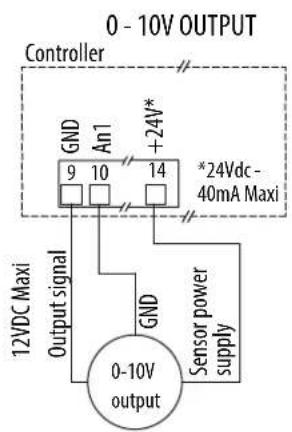
flowchart
graph TD
    A["0 - 10V OUTPUT"] --> B["Controller"]
    B --> C["GND An1 9 10 14"]
    B --> D["GND An1 +24V*"]
    C --> E["12VDC Maxi Output signal"]
    D --> F["*24Vdc - 40mA Maxi"]
    G["0-10V output"] --> H["GND Sensor power supply"]
    H --> I["Sensor power supply"]
0-LS-HS installation diagram, with adjustable LS and HS
The PV and the GV are adjusted by a VRPZ VOLTAGE variator (accessory not supplied). 0-LS-HS choice with the VRPZ.

Wiring for regulation according to the deviation between the set point / external measurement
flowchart
graph TD
    A["Controller"] --> B["CVF/REB-ECOWATT"]
    B --> C["Instead of the shunt"]
    C --> D["Output signal GND"]
    D --> E["Power supply (V)"]
    E --> F["On/OFF"]
    F --> G["1 2 3 4 5"]
    G --> H["P"]
    H --> I["Start/Stop +24V"]
    I --> J["9 10 11"]
    J --> K["GND An1 +10V"]
    K --> L["Instead of the potentiometer"]

flowchart
graph TD
    A["0 - 10V OUTPUT"] --> B["Controller"]
    B --> C["An2 12"]
    B --> D["GND 13"]
    B --> E["+24V* 14"]
    B --> F["GND 15"]
    B --> G["Speed-Output 16"]
    B --> H["*24Vdc - 40mA Maxi"]
    I["12VDC Maxi Output signal"] --> J["GND"]
    J --> K["0 - 10V Output"]
    L["Sensor power supply"] --> M["Shunt"]
    M --> N["GND"]
5.8.2 Speed adjustment
By potentiometer, CVF/REB-ECOWATT type remote control or 0-10V signal.
By default the roof fan is set to its maximum speed, in bold in the table below.
The potentiometer in the controller allows you to change the speed of the turbine to adjust the flow rate.
The adjustment can be given by the CVF/REB-ECOWATT type remote control or a 0-10V signal.
Correspondence table between the potentiometer graduation, the voltage applied on terminal 10 and the speed.
| Graduation potentiometer | Voltage (V) at terminal 10 | ILHB/T-ECOWATT 500 | ILHB/T-ECOWATT 630 | ILHB/T-ECOWATT 710 |
| 0 | 0 | 200 rpm | 200 rpm | 200 rpm |
| 2 | 2 | 460 rpm | 400 rpm | 410 rpm |
| 4 | 4 | 720 rpm | 600 rpm | 620 rpm |
| 6 | 6 | 980 rpm | 790 rpm | 830 rpm |
| 8 | 8 | 1 240 rpm | 980 rpm | 1 040 rpm |
| 10 | 10 | 1 500 rpm | 1 180 rpm | 1 250 rpm |
For information: The flow rate is proportional to the speed of rotation.
Q _ v 2 = Q _ v 1 × ( N _ 2N _ 1) Where N is the speed of rotation.
Speed adjustment 0 / LS / HS (adjustable LS and HS)
The adjustment can be done with a VRPZ voltage variator.
The low speed and the high speed are adjusted with the VRPZ, see VRPZ operating instructions.
Speed adjustment by Modbus BMS
The adjustment can be done with a Modbus BMS. For the Modbus connection settings, refer to § "5.2.4 Modbus connection - Connection to a BMS".
After you have wired your Modbus link:
Turn on the power to connect yourself to the controller. The roof fan wheel must be stopped.
| Steps | Register numbers | Value to be entered | |
| 1 - Access to Level 1 | 8 | 1 | |
| 2 - Change in the operating mode of the controller | 10 | 2 | |
| 3 - Enabling of the on/off in Modbus | 13 | 1 | |
| 4 - Saving of changes | 8 | 10000 | |
| 5 - Changing the set point | 0 | ||
| Fan stop | 13 | 0 | |
| Register set point 0 | ILHB/T-ECOWATT500 | ILHB/T-ECOWATT630 | ILHB/T-ECOWATT710 |
| 1000 | 150 rpm | 120 rpm | 125 rpm |
| 2000 | 300 rpm | 240 rpm | 250 rpm |
| 3000 | 450 rpm | 350 rpm | 375 rpm |
| 4000 | 600 rpm | 470 rpm | 500 rpm |
| 5000 | 750 rpm | 590 rpm | 625 rpm |
| 6000 | 900 rpm | 710 rpm | 750 rpm |
| 7000 | 1 050 rpm | 830 rpm | 875 rpm |
| 8000 | 1 200 rpm | 940 rpm | 1 000 rpm |
| 9000 | 1 350 rpm | 1 060 rpm | 1 125 rpm |
| 10000 | 1 500 rpm | 1 180 rpm | 1 250 rpm |
5.9 ILHB/T-ECOWATT 3-phases - CAV constant flow rate control
During constant flow rate operation, the controller regulates the speed of the roof fan to obtain the flow rate. A display installed under the cap indicates the flow rate measured in m³/h. The flow rate set point can be adjusted by the potentiometer in the controller, by a CVF/REB-ECOWATT ON/OFF + variation remote control, by an external 0-10V output or by Modbus BMS.
5.9.1 Wiring
CAV type factory assembly and wiring, with or without display. Connection of the power supply to the INTZ switch to be done by the customer.

Wiring for accessories not supplied
When the flow rate set point is given by the CVF/REB-ECOWATT type remote control or the 0-10V output, the factory-fi tted potentiometer in the controller must be disconnected.
When the speed set point is given by the MODBUS BMS the factory-fi tted potentiometer in the controller must be disconnected, as well as the shunt between terminals 14 and 16.

5.9.2 Adjusting the flow rate set point
By potentiometer, CVF/REB-ECOWATT type remote control or 0-10V output.
The potentiometer in the controller allows you to change the flow rate set point.
The set point can be given by the CVF/REB-ECOWATT type remote control or a 0-10V output. The display shows you the measured flow rate.
For sizes 500 / 630 / 710 : the display shows m³/h x 1000.
| Graduation potentiometer | Flow rate (m3/h) | ||||||
| 500 | 630 | 710 | |||||
| 0 | 0 | 0 | 0 | ||||
| 1 | 3950 | 6770 | 7480 | ||||
| 2 | 5590 | 9570 | 10580 | ||||
| 3 | 6850 | 11720 | 12950 | ||||
| 4 | 7910 | 13530 | 14960 | ||||
| 5 | 8840 | 15130 | 16720 | ||||
| 6 | 9680 | N/A | 18320 | ||||
| 7 | 10460 | N/A | 19790 | ||||
| 8 | N/A | N/A | 21150 | ||||
| 9 | N/A | N/A | 22440 | ||||
| 10 | N/A | N/A | 23650 | ||||
N/A : max. flow rate already reached
Note: After each adjustment wait 1 minute for the fan speed to stabilize.
By Modbus BMS
The flow rate set point can be given by a Modbus BMS set point. For the Modbus connection settings, refer to § "5.2.4 Modbus connection - Connection to a BMS".
After you have wired your Modbus link:
Turn on the power to connect yourself to the controller. The roof fan wheel must be stopped.
| Steps | Register numbers | Value to be entered |
| 1 - Access to Level 1 | 8 | 1 |
| 2 - Change in the operating mode of the controller | 10 | 2 |
| 3 - Enabling of the on/off in Modbus | 13 | 1 |
| 4 - Saving of changes | 8 | 10000 |
| 5 - Changing the set point | 0 | Between 0 and 10,000 to defi ne the desired fl ow rate set point, see the table below |
| Fan stop | 13 | 0 |
| Register set point 0 | ILHB/T-ECOWATT500 | ILHB/T-ECOWATT630 | ILHB/T-ECOWATT710 |
| 1000 | 3 950 m3/h | 6 770 m3/h | 7480 m3/h |
| 2000 | 5 590 m3/h | 9 570 m3/h | 10 580 m3/h |
| 3000 | 6 850 m3/h | 11 720 m3/h | 12 950 m3/h |
| 4000 | 7 910 m3/h | 13 530 m3/h | 14 960 m3/h |
| 5000 | 8 840 m3/h | 15 130 m3/h | 16 720 m3/h |
| 6000 | 9 680 m3/h | N/A | 18 320 m3/h |
| 7000 | 10 460 m3/h | N/A | 19 790 m3/h |
| 8000 N/A N/A | 21 150 m | 3/h | |
| 9000 N/A N/A | 22 440 m | 3/h | |
| 10000 | N/A N/A | 23 650 m | 3/h |
5.10 ILHB/T-ECOWATT 3-phases - COP constant pressure control
During operation at constant pressure, the controller regulates the speed of the roof fan to obtain the set pressure. If the display is present on the roof fan, it will show you the pressure in Pa. The pressure set point can be adjusted by the potentiometer in the controller, by a CVF/REB-ECOWATT ON/OFF + variation remote control, by an external 0-10V output or by Modbus BMS.
5.10.1 Wiring
COP type factory assembly and wiring, with or without display. Connection of the power supply to the INTZ switch to be done by the customer.
INTZ 22 A
Wiring for accessories not supplied
When the pressure set point is given by the CVF/REB-ECOWATT type remote control or the 0-10V output, the factory-fi tted potentiometer in the controller must be disconnected.
When the speed set point is given by the MODBUS BMS the factory-fi tted potentiometer in the controller must be disconnected, as well as the shunt between terminals 14 and 16.
5.10.2 Adjusting the pressure set point
By potentiometer, CVF/REB-ECOWATT type remote control or 0-10V output.
By default the roof fan is set to obtain the pressure in bold in the table.
The potentiometer in the controller allows you to change the pressure set point.
The set point can be given by the CVF/REB-ECOWATT type remote control or a 0-10V output.
Correspondence table between the potentiometer graduation, the voltage applied on terminal 10 and the pressure set point.
| Graduation potentiometer | Voltage (V) at terminal 10 | Without display | With display |
| 1 1 100 Pa 160 Pa | |||
| 2 2 300 Pa 320 Pa | |||
| 3 3 500 Pa 480 Pa | |||
| 4 4 700 Pa 640 Pa | |||
| 5 5 800 Pa 800 Pa | |||
| 6 6 800 Pa 960 Pa | |||
| 7 7 800 Pa 1 120 Pa | |||
| 8 8 800 Pa 1 280 Pa | |||
| 9 9 800 Pa 1 440 Pa | |||
| 10 10 800 Pa 1 600 Pa |
If the roof fan has a display, the display will show you the pressure measured at the roof fan plate (see diagram below).

Note: After each adjustment wait 1 minute for the fan speed to stabilize.
By Modbus BMS
The pressure set point can be given by a Modbus BMS set point. For the Modbus connection settings, refer to §"5.2.4 Modbus connection - Connection to a BMS".
After you have wired your Modbus link:
Turn on the power to connect yourself to the controller. The roof fan wheel must be stopped.
Modbus register table:
| Steps Register numbers Value to be entered | ||
| 1 - Access to Level 181 | ||
| 2 - Change in the operating mode of the controller 10 | 2 | |
| 3 - Enabling of the on/off in Modbus | 13 | 1 |
| 4 - Saving of changes | 8 | 10000 |
| 5 - Changing the set point | 0 | Between 0 and 10,000 to define the desired pressure set point, see the table below |
| Fan stop | 13 | 0 |
| Without display With display | |
| Register set point 0 Pressure (Pa) Register set point 0 Pressure (Pa) | |
| 1 000 100 100 160 | |
| 2 000 300 200 320 | |
| 3 000 500 300 480 | |
| 4 000 700 400 640 | |
| 4 500 800 500 800 | |
| 4 500 à 10 000 800 600 960 | |
| 700 1 120 | |
| 800 1 280 | |
| 900 1 440 | |
| 1000 1 600 | |
6. MAINTENANCE
The maintenance frequency depends on the operating conditions. If the air is highly loaded with impurities, the duration between two visits must be shortened.
WARNING: Before any maintenance operation, cut off the power supply upstream of the casing and make sure that it cannot be re-established during the intervention (lockout).
The motors used do not require any particular maintenance. They are fitted with sealed greased-for-life ball bearings.
Perform a periodical check based on the following indications:
| Unit/Item At commissioning | Every 6 months minimum | |
| Turbine | Check the direction of rotation and the absence of friction between the moving parts and the fixed parts | Clean if necessary, check the absence of friction between the moving parts and the fixed parts |
| Controller | Check the connections, especially those to earth | Retighten the terminals if necessary, check the rated current |
| Switch | Check the connections, especially those to earth | Tighten the terminals if necessary |
| Protective grilles | Check the presence | Clean if necessary |
| Duct networks | Check the sealing | Clean if necessary |
| Fastenings | Check the tightness | Tighten the screws if necessary |
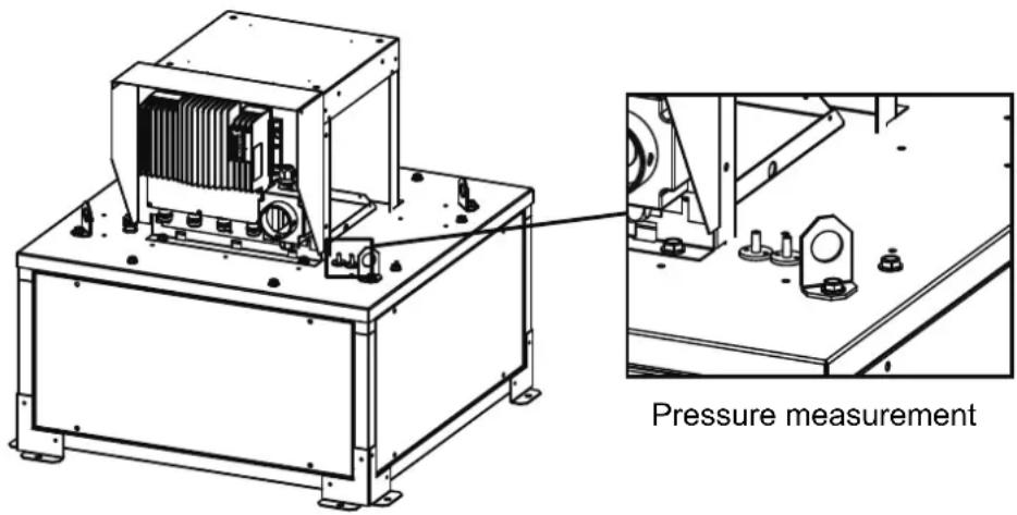
| Pressure tapping | Check the aeraulic connections | Check the operation |
7. WASTE MANAGEMENT
7.1 Treatment of Packagings and non dangerous wastes
The packagings (unconsigned pallets, cartons, fi lms, wooden boxes) and other non dangerous wastes must be made reusable by an approved service provider. It is strictly prohibited to burn, bury or dump them in nature.
7.2 Treatment of a Professional WEEE
This product must not be dumped or treated with household refuse, but must be deposited in an appropriate collection point for waste electrical and electronic equipment (WEEE).

Ref. NT-51907601-ILHB-ILHT-ECOWATT-AN-170711
- INDICE
- GENERAL....3
- PRODUCT PRESENTATION......4
- INSTALLATION 5
- ELECTRICAL CONNECTION 9
- COMMISSIONING AND SETTING....11
- MAINTENANCE....34
- WASTE MANAGEMENT 35
- GENERAL
- Disclaimers
- Safety instructions
- Storage
- Warranty
- PRODUCT PRESENTATION
- Construction
- Motor
- Kitchen Option
- INSTALLATION
- Dimensions and weight (mm)
- Summary charts of assembly and accessories
- Accessories (dimensions in mm)
- Double suction plenum
- DRAIN (KITCHEN OPTION)
- Casing assembly
- ELECTRICAL CONNECTION
- Preliminary precautions
- Electrical characteristics
- Wiring of INTZ safety switch
- Wiring of version with INTZ safety switch 1V15
- Wiring of version with INTZ safety switch 1V22
- COMMISSIONING AND SETTING
- Preliminary precautions
- Controllers
- Controller terminal block
- Adjustment potentiometer
- Fault correction
- For sizes 355/400/450
- For sizes 500/630/710
- Modbus connection - Connection to a BMS
- Default configuration settings
- Input register table
- Operation for smoke extraction
- Ventilation fault indication
- ILHB/T-ECOWATT Single-phase - VAV variable flow rate control
- VAV - Slaving to an external signal
- VAV - Regulation according to the deviation between the set point / external measurement
- Connection
- Wiring for manual adjustment and slaving to an external signal
- 0-LS-HS installation diagram, with adjustable LS and HS
- Speed adjustment (unregulated VAV)
- By potentiometer, or CVF/REB-ECOWATT type remote control.
- By 0-10V output
- Speed adjustment 0 / LS / HS (adjustable LS and HS)
- Speed adjustment by the Modbus BMS
- ILHB/T-ECOWATT Single-phase - CAV constant flow rate control
- Wiring
- Wiring for accessories not supplied
- Adjusting the flow rate set point,
- By potentiometer, CVF/REB-ECOWATT type remote control or 0-10V output.
- By Modbus BMS
- ILHB/T-ECOWATT Single-phase - COP constant pressure control
- Wiring
- Adjusting the pressure set point
- By potentiometer, CVF/REB ECOWATT type remote control or 0-10V output.
- ILHB/T-ECOWATT 3-phases - VAV variable flow rate control
- Wiring
- Wiring for manual adjustment and slaving to an external signal.
- Speed adjustment
- By potentiometer, CVF/REB-ECOWATT type remote control or 0-10V signal.
- Speed adjustment by Modbus BMS
- ILHB/T-ECOWATT 3-phases - CAV constant flow rate control
- Wiring
- Adjusting the flow rate set point
- ILHB/T-ECOWATT 3-phases - COP constant pressure control
- Wiring
- Adjusting the pressure set point
- MAINTENANCE
- WASTE MANAGEMENT
- Treatment of Packagings and non dangerous wastes
- Treatment of a Professional WEEE
Brand : Soler & Palau
Model : ILHB-ILHT ECOWATT
Category : Household Fan