MELLIZO - Household Fan Soler & Palau - Free user manual and instructions
Find the device manual for free MELLIZO Soler & Palau in PDF.


| Product Type | Twin Inline Centrifugal Fan |
| Brand | Soler & Palau |
| Model | MELLIZO |
| Fan Configuration | Two independent fans in acoustically lined cabinet; run and standby with duty-share (3-24 hours) |
| Speed Control | Variable via 0-10V, REB-CVF, REB-ECOWATT; fixed speeds via installer-defined potentiometers (Min, Mid, Max) with 3V minimum output |
| Remote Switching | Up to 3 volt-free contacts or 230V inputs; external fire shut-off switch |
| Fault Detection | Tacho pulse monitoring, low current sensing, airflow switch/DPS input; 60-second start-up delay |
| Outputs | Digital display (run/stop/fault, speed %, countdown); relay outputs (Fan A, Fan B, Fault) up to 8A/230V |
| Timer Function | Adjustable over-run timer 0-15 minutes for enable and boost |
| Power Supply | 230V AC, 50Hz (check nameplate) |
| Maximum Ambient Temperature | 40°C for control board |
| Minimum Clearance | 150mm around control enclosure for cooling; access gap in front |
| Installation | Professional installation required; vertical airflow orientation; duct or wall mount |
| Maintenance | Regular inspection; clean impeller and motor without unbalancing; disconnect power |
| Safety | Disconnect from mains before servicing; comply with local electrical regulations |
| Warranty | 24 months from purchase date against defective materials and workmanship |
| Compliance | EMC Directive 2014/30/EU; LVD; Machinery Directive; various EN standards |
Frequently Asked Questions - MELLIZO Soler & Palau
User questions about MELLIZO Soler & Palau
0 question about this device. Answer the ones you know or ask your own.
Ask a new question about this device
Download the instructions for your Household Fan in PDF format for free! Find your manual MELLIZO - Soler & Palau and take your electronic device back in hand. On this page are published all the documents necessary for the use of your device. MELLIZO by Soler & Palau.
USER MANUAL MELLIZO Soler & Palau
natural_image
Exterior view of a large industrial air duct or fan unit with a control panel and circular vent (no visible text or symbols)INDEX
- RECOMMENDATIONS......5
- GENERAL....5
2.1. Speed Control Inputs....5
2.2. Installer-defined Fixed Speed Control 5
2.3. Remote Switching....5
2.4. Fan-Fail Detection by Fault Sensing....5
2.5. Outputs .... 5
2.6. Analog Switch Outputs....5
- TRANSPORT AND HANDLING....6
- SAFETY RULES 6
4.1. ON INSTALLATION....6
4.2. AT START UP 6
- MECHANICAL INSTALLATION....7
- MELLIZO POWER CONNECTIONS....8
- CONTROL WIRING....9
7.1. REMOTE ENABLE (VOLT-FREE CONTACT) 9
7.2. REMOTE ENABLE (230V)....10
7.3. 0-10V (1 SIGNAL)....11
7.4. 0-10V (2 SIGNALS)....12
7.5. REB-CVF 13
7.6. REB-ECOWATT....14
7.7. PREP/COOK SWITCH....15
7.8. 3-SET SPEEDS (VOLT-FREE CONTACT)....16
7.9. 3-SET SPEEDS (230V)....17
7.10. AIRSENS (0-10V)....18
7.11. AIRSENS (TRICKLE/BOOST)....19
7.12. AIRSENS (REMOTE ENABLE)....20
7.13. EXTERNAL FAULT....21
7.14. RELAY OUTPUT....22
7.15. TIMER FUNCTION....23
- MAINTAINENCE 24
- Warranty....24
- RECYCLING....24
- EC DECLARATION OF CONFORMITY....25
-
DESIGNATION OF EQUIPMENT 25
-
GUARANTEE......25
1. RECOMMENDATIONS
You have purchased a MELLIZO twin fan designed specifically by Soler & Palau to perform the functions described in the table of contents.
Before you install and start up this product, please read this instruction book carefully because it contains important information for your safety and the safety of users during installation, use and maintenance. Once installation is complete, please pass the instruction book on to the end user. Please check that the equipment is in perfect condition when you unpack it since any factory defect is covered under the S&P guarantee. Please also check that the equipment is the one that you have ordered and that the information on the instruction plate meets your requirements.
2. GENERAL
The Mellizo range comprises of two inline centrifugal fans in an acoustically lined cabinet; each fan works independently for run and standby plus 3 to 24 hours duty-share function with the display indicating the status of the unit.
2.1. Speed Control Inputs
• Variable Speed Control
• Manual variable speed control via an optional secondary S&P REB ECOWATT or REB-CVF controller, or
- Automated variable speed control via a 0-10V signal from an external source.
2.2. Installer-defined Fixed Speed Control
- An upon-installation defined duty either continuous or on-demand (triggered by an external switch), or
- One, two or three speeds defined during installation to provide a minimum/middle/maximum speed ventilation system, the middle and maximum speeds being selected by an external switch/sensor (either Volt-free and/or 230V).
- Note that there is a 3-Volt minimum output to the fan to ensure start-up momentum.
2.3. Remote Switching
- The switching between the (up to) three speeds can be activated by either:
• (Up to) Three Volt-free contacts, or
• (Up to) Three 230V supply inputs - On/Off – Volt-Free Contact and/or 230V
- External Fire Fan Shut-Off Switch – An external “Fire” switch (Volt-Free) can be connected, If the switch opens signifying that the fire alarm has been activated, then the MULTI-REG Controller will automatically stop the fan.
2.4. Fan-Fail Detection by Fault Sensing
• Automatic monitoring of the impeller rotation via the Tacho pulse (frequency generator) signal.
- Low current sensing to indicate a connection open circuit problem.
- Sixty seconds time-delay of fault detection on start-up to allow input levels to normalise.
- Facility to connect an Airflow Switch or Differential Pressure Switch (DPS), for use on fans where other options are not practical. There is approximately a 60 seconds delay in the operation of the airflow switch monitoring system, to allow full airflow to develop.
2.5. Outputs
- Digital Display
- Running, Stopped and/or fault condition.
- Fan speed percentage and 0-10V output condition.
- Countdown to fault status monitoring condition (allows fan to gain speed).
- Diagnostic – Reasons for fan stop/fail.
2.6. Analog Switch Outputs
- Output to BMS of fan run and fault indicated by an individual set of contacts capable of controlling a maximum load of up to 230 Volts at 8 Amps.
3. TRANSPORT AND HANDLING
- The equipment packaging has been designed to withstand normal transport conditions. The equipment must not be transported without its original packaging as it could become damaged.
- The product must be stored in its original packaging and in a dry and clean place until it is installed. Do not accept any equipment that is not supplied in its original packaging or that shows signs of having been tampered with.
- Prevent the packaging from falling or being knocked
- Do not place heavy loads on top of it.
- When handling heavy products, adequate lifting equipment techniques and equipment should be used to avoid injury.
- Do not lift a product by pulling the wires, terminal/control enclosure, shutter or impeller to avoid damaging the product.
4. SAFETY RULES
4.1. ON INSTALLATION
• Installation and commissioning must be done by a qualified professional specialist.
- Ensure that installation complies with mechanical and electrical regulations in each country.
- Once commissioned, the equipment must comply with the following Directives:
- Standard for Low Pressure Instalments 2006/95/CE
- Machinery Standard 2006/42/CE
- Standard for Electromagnetic Compatibility 2004/108/CE
- Do not use this equipment in explosive or corrosive atmospheres.
4.2. AT START UP
- Make sure there are no loose elements near the ventilator, as they could run the risk of being sucked up by it. If it is going to be installed in a duct, check that it is clean of any element that could be sucked up by the ventilator.
- When installing an apparatus, make sure that all the fittings are in place and that the structure which supports it is resistant enough to bear its weight at full functioning power.
- Before you handle this equipment, ensure it is disconnected from the mains power supply.
- Check that the mains voltage and frequency are the same as specified on the name plate.
- Follow the wiring diagram to make the electrical connections.
- Check that the earthing, if any, is correct and that the thermal and surge protection has been connected and are within the relevant limits.
- If a ventilator is installed in a duct, the duct must be exclusively for the ventilation system.
5. MECHANICAL INSTALLATION
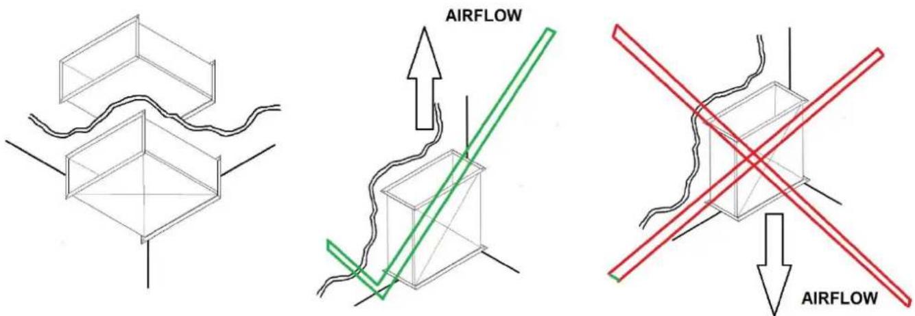
The product should only have the airflow going vertically up and horizontally. In this orientation it is suitable for fitment onto a suitable supportive structure and secured through the 4 fixing holes provided.
- Leave an air space of not less than 150mm around the edges control enclosure to allow cooling air to flow freely.
- Leave an additional gap in front of the control enclosure lid to allow for access during installation/wiring/maintenance.
- Do not install in close proximity to other heat sources.
• The maximum ambient temperature for the control board must not exceed 40°C.
The 2 fans integrated into the product are separately wired into a MELLIZO control panel located in an enclosure box positioned on the external casing.
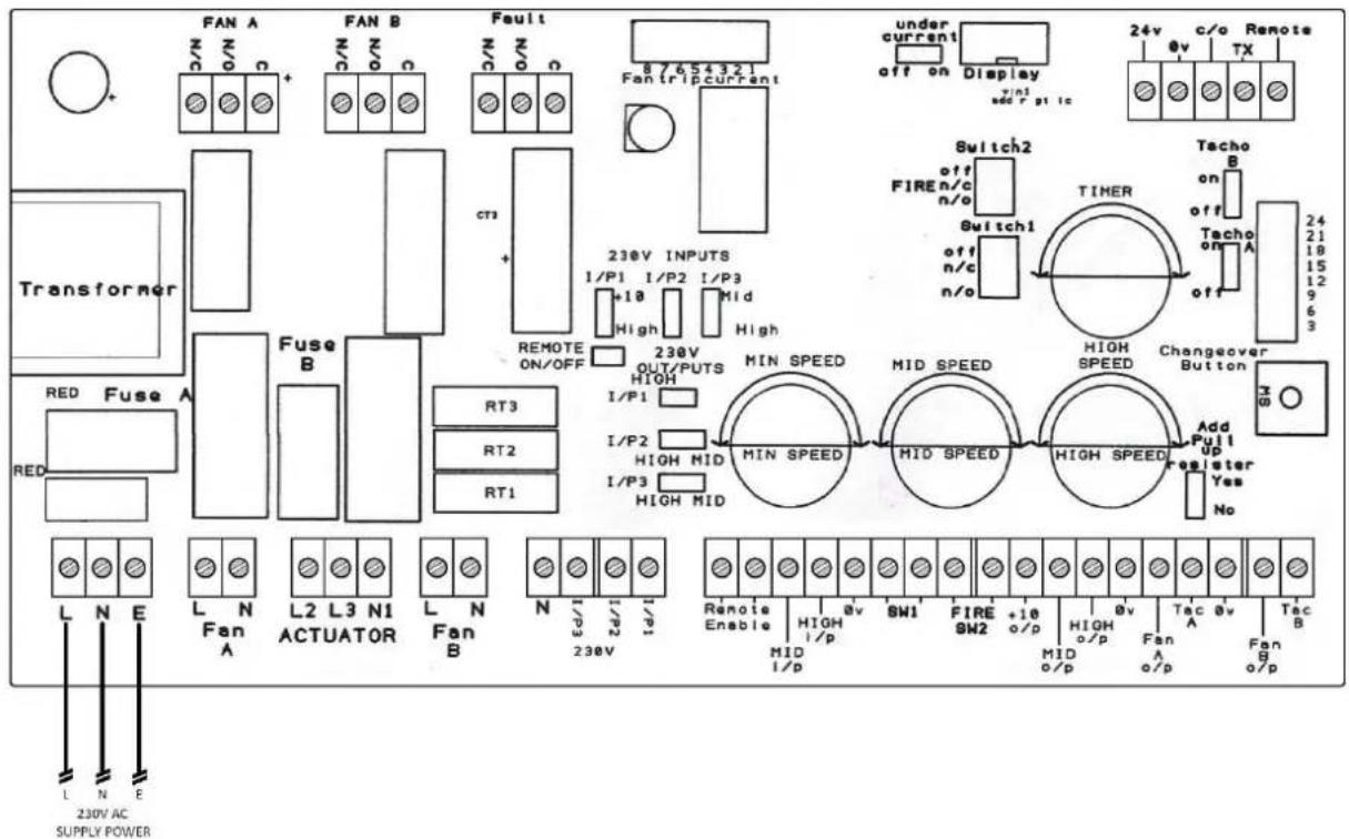
6. MELLIZO POWER CONNECTIONS
This basic wiring must be followed for every installation!!!
L - Live
N - Neutral
E - Earth
7.1. REMOTE ENABLE (VOLT-FREE CONTACT)
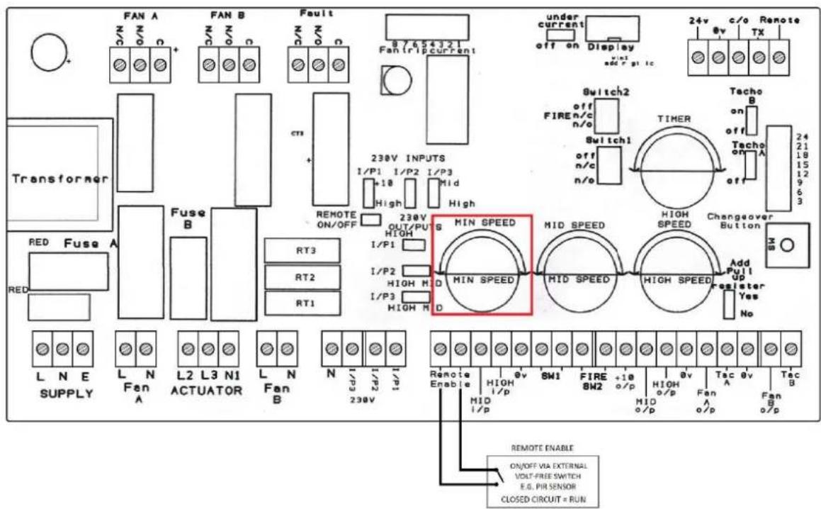
Fan speed set-point (Min Speed)
The speed is defined by the 'Min speed' Potentiometer, by rotating the potentiometer dial it will change the set speed of the fan.
7.2. REMOTE ENABLE (230V)

Fan speed set-point (Min Speed)
The speed is defined by the 'Min speed' Potentiometer, by rotating the potentiometer dial it will change the set speed of the fan.
7.3. 0-10V (1 SIGNAL)
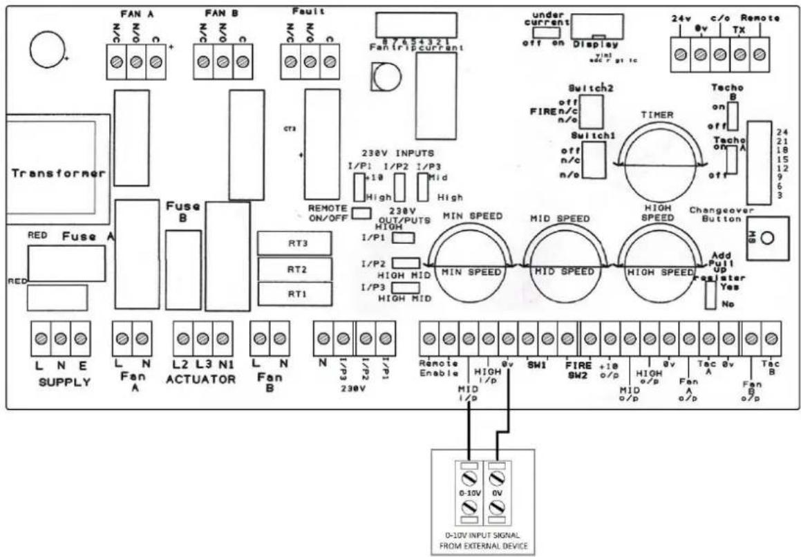
PRIOR TO ENERGISING THE MULTI-REG, THE INSTALLER MUST SET ALL THREE OF THE SPEED POTENTIOMETERS TO THEIR MINIMUM (FULLY ANTI-CLOCKWISE)!!!
Fan speed (0-10V)
The speed is defined by the voltage from the 0 - 10V signals from the external devices; the minimum output is 3V.
7.4. 0-10V (2 SIGNALS)
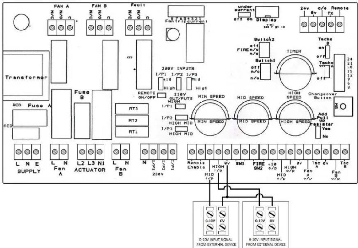
PRIOR TO ENERGISING THE MULTI-REG, THE INSTALLER MUST SET ALL THREE OF THE SPEED POTENTIOMETERS TO THEIR MINIMUM (FULLY ANTI-CLOCKWISE)!!!
Fan speed (0-10V)
The speed is defined by the highest voltage from the two 0 - 10V signals from external devices; the minimum output is 3V.
7.5. REB-CVF
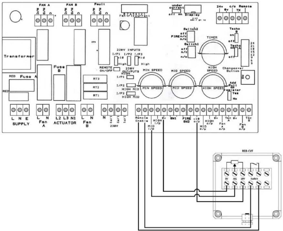
PRIOR TO ENERGISING THE MULTI-REG, THE INSTALLER MUST SET ALL THREE OF THE SPEED POTENTIOMETERS TO THEIR MINIMUM (FULLY ANTI-CLOCKWISE)!!!
Fan speed
The speed is defined by rotating the dial on the REB-CVF.
7.6. REB-ECOWATT

PRIOR TO ENERGISING THE MULTI-REG, THE INSTALLER MUST SET ALL THREE OF THE SPEED POTENTIOMETERS TO THEIR MINIMUM (FULLY ANTI-CLOCKWISE)!!!
Fan speed
The speed is defined by rotating the dial on the REB-ECOWATT.
7.7. PREP/COOK SWITCH

Prep speed set-point (Min speed)
The speed is defined by the 'Min speed' Potentiometer, by rotating the potentiometer dial it will change the set speed of the fan between 3-10V.
Cook speed set-point (High speed)
The speed is defined by the 'High speed' Potentiometer, by rotating the potentiometer dial it will change the set speed of the fan between 3-10V.
7.8. 3-SET SPEEDS (VOLT-FREE CONTACT)
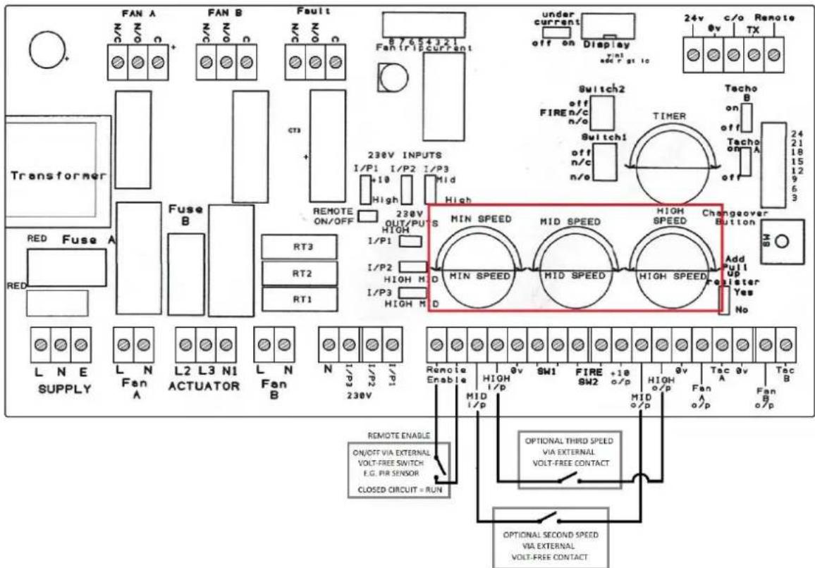
Trickle speed set-point (Min speed)
The speed is defined by the 'Min speed' Potentiometer, by rotating the potentiometer dial it will change the set speed of the fan between 3-10V.
Second speed set-point (Mid speed)
The speed is defined by the 'Mid speed' Potentiometer, by rotating the potentiometer dial it will change the set speed of the fan between 3-10V.
Third speed set-point (High speed)
The speed is defined by the 'High speed' Potentiometer, by rotating the potentiometer dial it will change the set speed of the fan between 3-10V.
7.9. 3-SET SPEEDS (230V)

Trickle speed set-point (Min speed)
The speed is defined by the 'Min speed' Potentiometer, by rotating the potentiometer dial it will change the set speed of the fan between 3-10V.
Second speed set-point (Mid speed)
The speed is defined by the 'Mid speed' Potentiometer, by rotating the potentiometer dial it will change the set speed of the fan between 3-10V.
Third speed set-point (High speed)
The speed is defined by the 'High speed' Potentiometer, by rotating the potentiometer dial it will change the set speed of the fan between 3-10V.
The speed is defined by the AIRSENS sensor, which will proportionally increase its control voltage depending on the pollutants or humidity in the air.
7.11. AIRSENS (TRICKLE/BOOST)

Trickle speed set-point (Min speed)
The speed is defined by the 'Min speed' Potentiometer, by rotating the potentiometer dial it will change the set speed of the fan between 3-10V.
Boost speed set-point (High speed)
The speed is defined by the 'High speed' Potentiometer, by rotating the potentiometer dial it will change the set speed of the fan between 3-10V.
7.12. AIRSENS (REMOTE ENABLE)
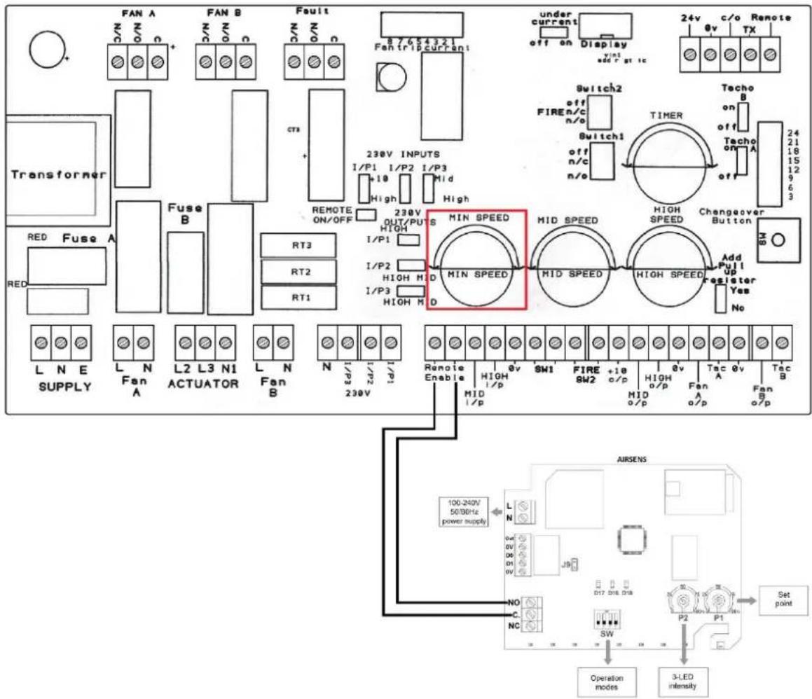
Fan speed set-point (Min Speed)
The speed is defined by the 'Min speed' Potentiometer, by rotating the potentiometer dial it will change the set speed of the fan.
7.13. EXTERNAL FAULT

External fault (SW1)
When the fan is in normal running conditions the switch should be in the closed position. If additional switches are required then can be connected in series. During start-up there is a 60 seconds delay to allow the airflow to increase. When the fault switch opens signifying loss of airflow, the controller will automatically stop the fan and display "EXTERNAL SW1 FAULT".
Following an "EXTERNAL SW1 FAULT", a manual re-start will be required.
Fire shut-off (SW2)
When the fan is in normal running conditions the switch should be in the closed position. When the fault switch opens signifying the fire alarm has been activated, the controller will automatically stop the fan and display "FIRE ALARM ACTIVATED".
Following an "FIRE ALARM ACTIVATED", a manual re-start will be required
7.14. RELAY OUTPUT
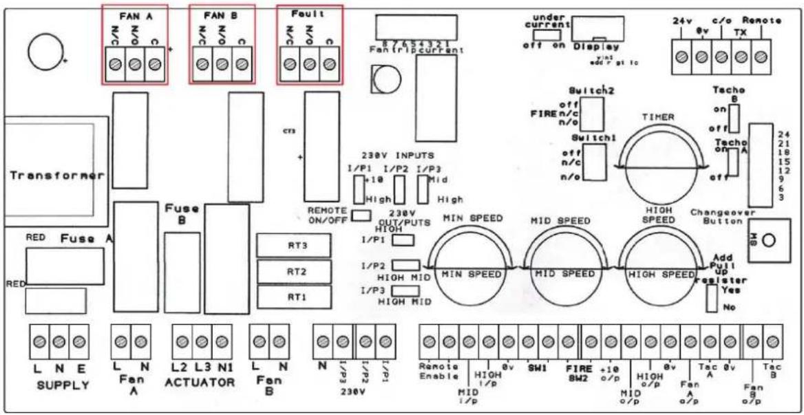
Fan A (Maximum current load 8A)
Fan A is a run relay that will activate when Fan A is operating, below is the operation:
Fan Running – Continuity between COM and NO
Fan Stopped – Continuity between COM and NC
Fan B (Maximum current load 8A)
Fan B is a run relay that will activate when Fan B is operating, below is the operation:
Fan Running – Continuity between COM and NO
Fan Stopped – Continuity between COM and NC
Fault (Maximum current load 8A)
Fault is a fault relay that will activate when either fan is in fault condition, below is the operation:
Fan Running/Stopped – Continuity between COM and NC
Fault with Fan – Continuity between COM and NO
7.15. TIMER FUNCTION

Timer function
The over-run timer works when you alter the 'Timer' potentiometer, this will allow you to add an over-run of 0 to 15 minutes; the over-run function will operate for both remote enable and boost functions.
If a 10-minute over-run is set then the remote enable will over-run for 10 minutes and the boost will over-run for 10 minutes.
8. MAINTAINENCE
Before manipulate the device, make sure that it is disconnected from the mains and that no one can turn it on during the intervention.
The apparatus must be regularly inspected. These inspections should be carried out bearing in mind the ventilator's working conditions, in order to avoid dirt or dust accumulating on the impeller, motor or back-draught shutter. This could be dangerous and perceptibly shorten the working life of the ventilator unit.
While cleaning, great care should be taken not to unbalance the impeller or motor.
In all maintenance and repair work, the safety regulations in force in each country must be observed.
9. Warranty
S&P Limited Warranty
24 (TWENTY-FOUR) MONTH PRODUCT WARRANTY
S&P UK Ventilation Systems Limited warrants that the MULTI-REG Control will be free from defective materials and workmanship for the period of 24 (twenty-four) months from the date of original purchase. In the event that we find any part is defective the product will be repaired or at the company's discretion, replaced without charge provided that the product has been installed in accordance with the enclosed instructions and all applicable standards and national and local building standards.
IF CLAIMING UNDER WARRANTY
Please return the completed product, carriage paid, to your local authorized distributor. All returns must be accompanied by a valid Invoice of Sale. All returns must be clearly marked "Warranty Claim", with an accompanying description stating the nature of the fault.
THE FOLLOWING WARRANTIES DO NOT APPLY
- Damages resulting from improper wiring or installation.
- Damages resulting when using the fan/control with fans/motors/controls/sensors other than those supplied and manufactured by the S&P Group of Companies.
- Removal or alteration of the S&P data plate label.
WARRANTY VALIDATION
- The end user must keep a copy of the Invoice of Sale to verify a purchase date.
10. RECYCLING
Dismantling and recycling must be carried out by qualified personnel and in compliance with local and international regulations.
Disconnect the electrical equipment from the power supply making sure that no one can start it during the operation.
Disassemble and eliminate the parts to be replaced according to current national and international standards.

EEC legislation and our consideration of future generations mean that we should always recycle materials where possible; please do not forget to deposit all packaging in the appropriate recycling bins. If your device is also labelled with this symbol, please take it to the nearest Waste Management Plant at the end of its serviceable life.
11. EC DECLARATION OF CONFORMITY
Herewith we declare that the fan/control designated below, on the basis of its design and construction in the form brought onto the market by us is, in accordance with the relevant EC Council Directives on Electromagnetic Compatibility. If alterations are made to the apparatus without prior consultations with us, this declaration becomes invalid. We further declare that the equipment identified below may be intended to be assembled with other equipment/machines to constitute machinery, which shall not be put into service until the assembled machinery has been declared in conformity with the provisions of these relevant EC Council Directives.
12. DESIGNATION OF EQUIPMENT
EMC Directive 2014/30/EU based on conformity to the requirements of: -
BS EN IEC 61000-6-3:2021 // BS EN 61000-4-4:2012 // BS EN IEC 61000-4-11:2020 // BS EN 61000-4-2:2009 // BS EN 61000-4-8:2010 // BS EN IEC 61000-4-3:2020 // BS EN 61000-4-6:2014 // BS EN 61000-4-5:2014+A1:2017
EN 60204-1:2018 // EN 61000-3-2:2014 // EN 61000-3-3:2013 // EN 61000-6-2: 2005 + AC:2005//EN 61000-6-3:2007+A1:2011+AC:2012 // //EN62311:2008 // EN ISO 12100:2010 // EN ISO 12499:2008 //EN ISO 13857:2019
13. GUARANTEE
S&P Limited Warranty
24 (TWENTY-FOUR) MONTH PRODUCT WARRANTY
S&P UK Ventilation Systems Limited warrants that the CAB TWIN ECOWATT N /ACODS fan control will be free from defective materials and workmanship for the period of 24 (twenty-four) months from the date of original purchase. In the event that we find any part is defective the product will be repaired or at the company's discretion, replaced without charge provided that the product has been installed in accordance with the enclosed instructions and all applicable standards and national and local building standards.
IF CLAIMING UNDER WARRANTY
Please return the completed product, carriage paid, to your local authorized distributor. All returns must be accompanied by a valid Invoice of Sale. All returns must be clearly marked "Warranty Claim", with an accompanying description stating the nature of the fault.
THE FOLLOWING WARRANTIES DO NOT APPLY
- Damages resulting from improper wiring or installation.
- Damages resulting when using the fan/control with fans/motors/controls/sensors other than those supplied and manufactured by the S&P Group of Companies.
- Removal or alteration of the S&P data plate label.
WARRANTY VALIDATION
The end user must keep a copy of the Invoice of Sale to verify a purchase date.

S&P UK VENTILATION SYSTEMS LTD
S&P HOUSE
WENTWORTH ROAD
RANSOMES EUROPARK
IPSWICH
SUFFOLK
TEL. 01473 276890
WWW.SOLERPALAU.CO.UK


REF. REV-1

- INDEX
- RECOMMENDATIONS
- GENERAL
- Speed Control Inputs
- Installer-defined Fixed Speed Control
- Remote Switching
- Fan-Fail Detection by Fault Sensing
- Outputs
- Analog Switch Outputs
- TRANSPORT AND HANDLING
- SAFETY RULES
- ON INSTALLATION
- AT START UP
- MECHANICAL INSTALLATION
- MELLIZO POWER CONNECTIONS
- REMOTE ENABLE (VOLT-FREE CONTACT)
- REMOTE ENABLE (230V)
- 0-10V (1 SIGNAL)
- PRIOR TO ENERGISING THE MULTI-REG, THE INSTALLER MUST SET ALL THREE OF THE SPEED POTENTIOMETERS TO THEIR MINIMUM (FULLY ANTI-CLOCKWISE)!!!
- 0-10V (2 SIGNALS)
- REB-CVF
- REB-ECOWATT
- PREP/COOK SWITCH
- Prep speed set-point (Min speed)
- Cook speed set-point (High speed)
- 3-SET SPEEDS (VOLT-FREE CONTACT)
- 3-SET SPEEDS (230V)
- Trickle speed set-point (Min speed)
- Second speed set-point (Mid speed)
- Third speed set-point (High speed)
- AIRSENS (TRICKLE/BOOST)
- Boost speed set-point (High speed)
- AIRSENS (REMOTE ENABLE)
- EXTERNAL FAULT
- External fault (SW1)
- Fire shut-off (SW2)
- RELAY OUTPUT
- TIMER FUNCTION
- Timer function
- MAINTAINENCE
- Warranty
- IF CLAIMING UNDER WARRANTY
- THE FOLLOWING WARRANTIES DO NOT APPLY
- WARRANTY VALIDATION
- RECYCLING
- EC DECLARATION OF CONFORMITY
- DESIGNATION OF EQUIPMENT
- GUARANTEE
- S&P UK VENTILATION SYSTEMS LTD
Brand : Soler & Palau
Model : MELLIZO
Category : Household Fan