
UTBS PRO-REG ECOWATT - Ventilation Soler & Palau - Free user manual and instructions
Find the device manual for free UTBS PRO-REG ECOWATT Soler & Palau in PDF.


| Type | Ventilation fan |
| Model | UTBS PRO-REG ECOWATT |
| Brand | Soler & Palau |
| Dimensions (W x H x D) | 300 x 300 x 150 mm |
| Weight | 2.5 kg |
| Power Supply | 230 V ~ 50 Hz |
| Power Consumption | 45 W |
| Airflow (Max) | 350 m³/h |
| Noise Level (Max) | 42 dB(A) |
| Speed Settings | 3 steps (low, medium, high) |
| Control Type | Regulator (PRO-REG) |
| Energy Efficiency | ECOWATT - low energy consumption |
| Mounting | Wall or ceiling |
| Material | ABS plastic |
| Protection Rating | IPX4 |
| Insulation Class | Class II |
| Filter | Washable foam filter (optional) |
| Included Accessories | Mounting bracket, screws, user manual |
| Warranty | 2 years |
| Certifications | CE, RoHS |
Frequently Asked Questions - UTBS PRO-REG ECOWATT Soler & Palau
User questions about UTBS PRO-REG ECOWATT Soler & Palau
0 question about this device. Answer the ones you know or ask your own.
Ask a new question about this device
Download the instructions for your Ventilation in PDF format for free! Find your manual UTBS PRO-REG ECOWATT - Soler & Palau and take your electronic device back in hand. On this page are published all the documents necessary for the use of your device. UTBS PRO-REG ECOWATT by Soler & Palau.
USER MANUAL UTBS PRO-REG ECOWATT Soler & Palau
INDEX
- OVERVIEW 4
- SAFETY STANDARDS AND "EC" MARKING 4
- GENERAL STANDARDS....4
- UNIT LABELING 5
- TECHNICAL CHARACTERISTICS....5
- HANDLING 8
- INSTALLATION....9
7.1. Overview 9
7.2. Identification unit parts....10
7.3. Installation site....10
7.4. Maintenance space....10
7.4.1. Dimensions....11
7.4.2. Space for maintenance....23
7.5. Assembling the modules....25
7.5.1. Move the fl ange from the main module to the accessory module....26
7.5.2. Additional filters mounting....27
7.5.3. Assembling flexible connections....27
7.5.4. Mixing module installation 27
7.5.5. Installation with isolation damper 28
7.6. Connecting the unit to the water network 29
7.7. Connecting the unit to the duct system 30
7.8. Direct expansion coils connection (DX) 31
7.9. Drainage system....32
7.10. Electrical connection....32
7.11. Temperature probes location 33
- START-UP PROCEDURE 35
- CONTROL FUNCTIONS....36
-
CONTROL DIAGRAM....38
-
REMOTE CONTROL OPERATION....41
11.1. Change language....41
11.2. Simplified menus / accesses....41
11.2.1.User level 41
11.2.2.Installer level....42
11.3. Operation fan modes....44
11.3.1. Constant airflow operation (CAV) 44
11.3.2. Variable airflow operation (VAV) 46
11.3.3. Constant pressure operation (COP) 47
11.3.4. Control slave of an external fan (For all working modes)....50
11.4. Postheater control....51
11.4.1. Constant supply air temperature maintenance 51
11.4.2. Constant ambient temperature maintenance....51
11.4.3. Temperature set point adaptation vs. outdoor temperature....52
11.4.4. Automatic control mode 52
11.5. Initial temperature setpoint 52
11.6. Time programming....53
11.7. Mixing module control (3 Ways) 56
11.7.1. Without mixing module....56
11.7.2. Control 56
11.7.3. Temperature control....56
11.7.4. , Control and temperature 56
11.8. Control of isolation damper 56
-
BOOST FUNCTION (only available in CAV and COP modes) 57
-
REMOTE STOP-START....57
-
FREE COOLING BY NIGHT 58
-
WATER HEATER FROST PROTECTION....59
-
RESET THE CORRIGO CONTROLLER....59
-
CONNECTION TO BUILDING MANAGEMENT SYSTEMS (BMS) 62
17.1.RTU Modbus 62
17.2. TCP/IP Bacnet 63
-
REPLACEMENT OF THE BATTERY FROM THE CORRIGO PROGRAMMABLE LOGIC CONTROLLER 63
-
OPERATION ANOMALIES 64
19.1.General anomalies....64
19.2. Failure list 65
-
EMERGENCY OPERATIONS....66
-
PREVENTIVE MAINTENANCE 66
21.1. Water coils 67
21.1.1. DX coils....67
21.2. Drainage system....67
21.3.Motors....67
21.4.Fans 67
21.5. Filters 67
21.5.1.Filter replacement 68
21.6. Coils 70
21.7. Dampers 71
21.8. Silencers....71
- WIRING DIAGRAMS 72
1. OVERVIEW
- We appreciate the trust you have placed in us by purchasing this device. You have purchased a high-quality product that has been manufactured in strict compliance with recognized technical regulations regarding safety, and in accordance with EC standards.
- Read this instruction booklet carefully, since it contains important information for your safety during the installation, use and maintenance of this product.
- Keep this booklet in case you need to consult it in the future.
- We ask that you make sure the equipment is in perfect condition when you unpack it, since any existing defect is covered by the S&P warranty.
- Technicians responsible for installing, start-up and maintenance must read the instructions and be familiar with them before starting work.
2. SAFETY STANDARDS AND "EC" MARKING
- S&P engineers are firmly committed to research and development to achieve products with improved efficiency that complies with current safety standards.
- The standards and recommendations indicated below reflect current standards in the field of safety, and therefore are based primarily on meeting standards of a general nature. Consequently, we recommend that all personnel exposed to risks adhere strictly to local regulations in force regarding hazard prevention.
- S&P is in no way responsible for any damage or injury caused to persons or objects resulting from failure to comply with safety standards, and any possible modifications to the product. The EC seal and statement of conformity serve as proof of the product's compliance with applicable European Community standards.
3. GENERAL STANDARDS
- Product risks have been analysed pursuant to the provisions of the Machinery Directive. This manual contains information intended for all personnel exposed to hazards, with the goal of preventing personal injuries or damage to objects resulting from mishandling or improper maintenance. All maintenance service work (corrective and preventive) must be performed with the equipment stopped and disconnected.
- To avoid danger of possible accidental start up ensure that the equipment is electrically isolated and locked. If this is not possible, warning signs should be placed on main distribution console that state:
"WARNING: controls disconnected for maintenance"
- Before connecting the power cable to the motors, make sure that the voltage on the line matches the voltage indicated on the unit's identification plate.
4. UNIT LABELING
- The unit comes with a variety of labels that must not be removed. Herewith sample labels and meaning:
| ICON / LABEL MEANING | |||
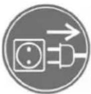 |  |  | Signs on fan access door, indicates that the unit must be disconnected, followed by a waiting period, since there are moving parts that constitute danger in case of access. |
 | Indicates the airflow direction through the unit. | ||
 |  | In case of units equipped with cold water coil, it shows the water inlet and outlet. | |
 |  | In case of units equipped with hot water coil, it shows the water inlet and outlet. | |
 | Unit identification plate, which indicates:- Model- Code- Serial number- Date of manufacture- Output power of installed motors (Kw)- Maximum absorbed current of motor (A)- Power of installed electric heater- Electrical supply | ||
5. TECHNICAL CHARACTERISTICS
VENTILATION SECTION
The UBTS-2 model incorporates a fan, while the UTBS-3,5 and 8 models have two. Each model has associated a certain size of fan and motor.
The integrated controller, makes it possible to adapt the working point to the needs of each installation, obtaining a high efficiency at the required working point.
| Model Maximum airfl ow (m3/h) | Fans | |||||||
| Quantity | Supply voltage | Sound pressure level (r.p.m.) | Motor power (kW) | Maximum intensity* (A) | ||||
| Chilled water coil/DX | Hot water coil | Electrical coil | ||||||
| UTBS-2 1300 2150 2150 1 230/I/50 2850 0,45 2 | ||||||||
| UTBS-3 2600 4000 4000 2 230/I/50 2850 2 x 0,45 3,9 | ||||||||
| UTBS-5 3750 5800 5800 2 230/I/50 2830 2 x 0,85 7,2 | ||||||||
| UTBS-8 6100 8000 8000 2 400/III/50 2600 | 2 x 1 3,6 | |||||||
* In units with two fans, the value corresponds to the sum of both fans.
COIL SECTION
Water coils
One or two water coils can be included in the section (one heating or one cooling coil or both at the same time).
The units can be supplied with 2 or 4 rows for heating coils and 4 or 6-row for cooling coils. If the unit includes a cooling coil it is always supplied as a standard with condensate drip tray made from stainless steel AISI 304 and a droplet eliminator.
The connections of the water coil and the drip tray can be ordered on left side or right side of the unit.
| Model | Airfl ow (m3/h) | Coils Thermal power (kW) | Inlet/Outlet connections | |||||
| Hot water coil | Chilled water coil | |||||||
| H2 | H4 | C4 | C6 | |||||
| 80°C/60°C | 50°C/45°C | 80°C/60°C | 50°C/45°C | 7°C/12°C | 7°C/12°C | |||
| UTBS-2 | 900 11,9 8,3 18,2 | 22,7 8,1 | 9,6 | 1-1/4" GM | ||||
| 1.200 14,4 10,0 | 22,7 | 15,5 10,0 | 11,9 | |||||
| UTBS-3 | 1.700 23,5 16,0 | 34,7 | 23,5 15,5 | 20,0 | 1-1/4" GM | |||
| 2.500 30,5 20,9 | 46,8 | 31,9 20,5 | 23,3 | |||||
| UTBS-5 | 2.500 33,9 23,3 | 51,2 | 34,7 23,2 | 29,2 | 1-1/4" GM | |||
| 3.500 42,7 29,4 | 66,6 | 45,2 29,6 | 38,4 | |||||
| UTBS-8 | 4.000 55,0 37,7 | 81,4 | 55,4 36,0 | 46,8 | 1-1/2" GM | |||
| 6.000 72,5 49,8 | 111,5 | 76,1 48,2 | 64,8 | |||||
* Air inlet temperature: -5°C, Rel. Hum: 80%
** Air inlet temperature: 32°C, Rel. Hum: 50%
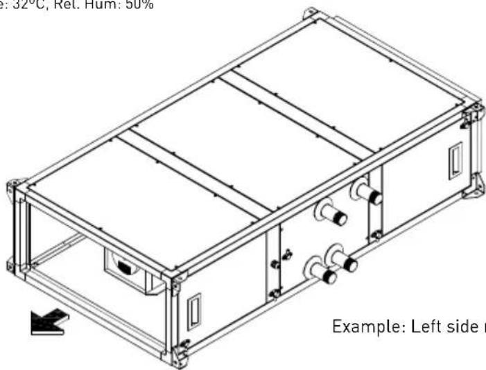
Example: Left side register
Electric heaters
The unit can be supplied with electric heaters made of shielded resistances with a galvanised sheet frame. The heaters are equipped with safety protection with manual and automatic reset. The heater has an anti-radiation screen to protect the filters.
| Model Available electric power / Stages | |||||
| UTBS-2 E4,5 4,5 kW/ 1et. E15 15,0 kW/ 2et. | |||||
| UTBS-3 E6 6,0 kW/ 1et. E15 15,0 kW/ 2et. E24 24,0 kW/ 2et. | |||||
| UTBS-5 E9 9,0 kW/ 2et. E15 15,0 kW/ 2et. E36 36,0 kW/ 3et. | |||||
| UTBS-8 E15 15,0 kW/ 2et. E24 24,0 kW/ 2et. E45 45,0 kW/ 3et. | |||||
Direct expansion coil (DX)
The unit can be supplied with expansion direct coils for R-410A gas. Compatible with the main control kits of the market.
4 rows coil
For applications with 100% recirculated air.
| Model | Air fl ow (m3/h) | Volu-me (dm3) | N° Sta-ges | ∅ Distrib- butor (Liquid line) | ∅ Co- lector (Gas Line) | COOLING HEATING | |||||||||
| Power* (kW) | Supply air Temp. (°C) | Rel. Hum. (%) | R410A Air- fl ow (kg/h) | ΔP R410A (kPa) | Power** (kW) | Supply air Temp. (°C) | Rel. Hum. (%) | R410A Air- fl ow (kg/h) | ΔP R410A (kPa) | ||||||
| UTBS-2 | 1.250 | 1,2 | 1 | 3/8" | 5/8" | 4,6 | 14,2 | 87 | 84,6 | 14,9 | 4,9 | 32,7 | 25 | 87,9 | 9,6 |
| UTBS-3 | 2.500 | 2,21 | 1 | 1/2" | 5/8" | 8,8 | 14,4 | 87 | 163,3 | 13,0 | 8,0 | 33,6 | 28 | 143,4 | 6,1 |
| UTBS-5 | 3.500 | 2,41 | 1 | 1/2" | 5/8" | 10,9 | 15,2 | 85 | 200,0 | 10,9 | 10,0 | 32,7 | 30 | 180,2 | 5,1 |
| UTBS-8 | 6.000 | 4,4 | 1 | 1/2" | 5/8" | 19,9 | 14,9 | 86 | 368,3 | 22,1 | 17,2 | 32,7 | 30 | 310,1 | 8,8 |
* Air Inlet 24°C / 50%R.H.
** Air Inlet 21°C / 50%R.H.
6 rows coil
For applications with 50% outdoor air/ 50% recirculated air.
| COOLING | HEATING | ||||||||||||||
| Model | Air flow (m3/h) | Volume (dm3) | No Stages | ∅ Distributor (Liquid line) | ∅ Collector (Gas Line) | Power * (kW) | Supply air Temp. (°C) | Rel. Hum. (%) | R410A Air-fl ow (kg/h) | ΔP R410A (kPa) | Power ** (kW) | Supply air Temp. (°C) | Rel. Hum. (%) | R410A Air-fl ow (kg/h) | ΔP R410A (kPa) |
| UTBS-2 | 1.250 | 2 | 1 | 1/2" | 5/8" | 10,0 | 14,5 | 94 | 185,3 | 8,6 | 10,5 | 34,4 | 17 | 190,5 | 5,1 |
| UTBS-3 | 2.500 | 3,31 | 1 | 1/2" | 5/8" | 19,4 | 14,9 | 94 | 358,6 | 25,3 | 19,9 | 30,8 | 18 | 359,0 | 13,7 |
| UTBS-5 | 3.500 | 4,3 | 1 | 1/2" | 3/4" | 26,6 | 15,2 | 94 | 490,5 | 18,6 | 27,6 | 30,6 | 18 | 498,0 | 10,3 |
| UTBS-8 | 6.000 | 8,4 | 2 | 2 x 1/2" | 2x 3/4" | 47,8 | 14,6 | 94 | 882,0 | 25,3 | 49,8 | 31,8 | 17 | 897,0 | 12,3 |
* Air Inlet 29°C / 55%R.H.
** Air Inlet 8°C / 75%R.H.
Filtered section
Filtration section with two alternatives:
- Long version P F7 with capacity for mounting two filters: F7 with very low built-in pressure drop and possibility of mounting a second filter (supplied as an accessory). The filter clamping system with articulated arms ensures excellent sealing of the filter assembly. Available filters G4, M5 and F9.
- M5 short version with the ability to fit a single M5 filter mounted using a guide system without filter clamps.
Available fi lters F6, F8 or F9 fi lters with an effi ciency level above 60%. The fi lters have been manufactured according to UNE 779:2013.
6. HANDLING
- When unit received, unpack and make sure the packaging is intact; any defect may indicate damage to the equipment. Review it carefully to make sure that no parts are missing.
- If there is any damage to the unit or the shipment is not complete, write down the problems on the delivery slip and send a claim to the carrier. Also report any problems to S&P.
- Components should be transported using appropriate hoist and slings. The equipment has corner lugs for loading and unloading.
- The UTBS PRO-REG units are delivered bolted in pallets.

- It is possible to manipulate by the unit using a forklift or crane. Handling machines must be adapted to the conditions of loading and lifting. In all cases, the lift must be carried out from the base of the device. The centre of gravity is NOT in the center of the unit. Before lifting the equipment ensure that gravity center of the device is entering the two blades of the forklift.
- The unit should be handled carefully and only horizontally.
7. INSTALLATION
7.1. OVERVIEW
- The technician responsible for equipment receipt must ensure that the characteristics of the existing power supply agree with the electrical data on the unit's identification plate.
- Before installing the equipment in its final position, make sure that the place where it will be located is strong enough to support its weight.
- Under no circumstances should these units be installed in flammable or explosive environments, in environments that contain oil vapours, salt air, or corrosive environments.
- Equipment installation can present hazards due to the material used, pressures in the system and the electrical components. For this reason, only trained and qualified service personnel may install service or repair the equipment.
- As a precaution, when performing operations inside the equipment, shut off the power at a main breaker. This serves to prevent any accidents involving the equipment's moving parts, which can start accidentally, well as to prevent any direct or indirect contact with live parts.
- When installing the unit, it must be levelled to allow for a good fit between the different modules, perfect condensate drainage and proper opening of the doors.
- To test whether the fan is in perfect condition, check the centering of the intake ring by turning the impeller by hand.
7.2. IDENTIFICATION UNIT PARTS
The main module may consist of three different sections: filter, coils and fans. However, one of the first two sections may not be included. The following illustration identifies the main components of the main module.

7.3. INSTALLATION SITE
- Avoid installing the unit in areas near heat sources or in damp areas where the unit might come in contact with water.
- It is recommended that the unit be installed in a place that is easily accessible for the installation. Provide sufficient room for maintenance, connection and drainage of condensate.
7.4. MAINTENANCE SPACE
- The installer should leave sufficient unobstructed space to allow free access to the unit for maintenance. The amount of space needed will depend on which side of the unit is performing the extraction. The unit is equipped with some side access doors for access to the filters and fans. To remove the coils, the side panel must be removed. Both the filters and the fans can be removed from either side of the unit.
7.4.1. Dimensions
Short version: Single fi lter type M5
Configuration with electric coil

F: Filter M5
E: Electrical coil (E4,5 to E45)
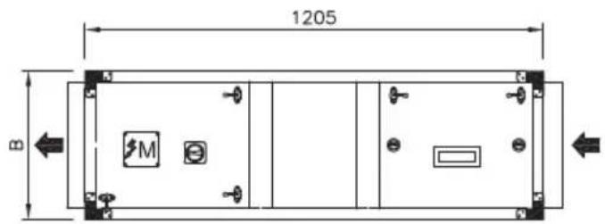
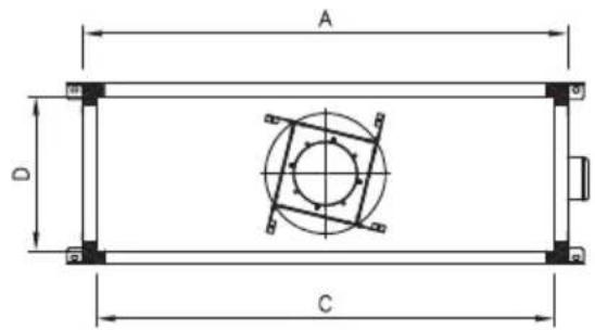
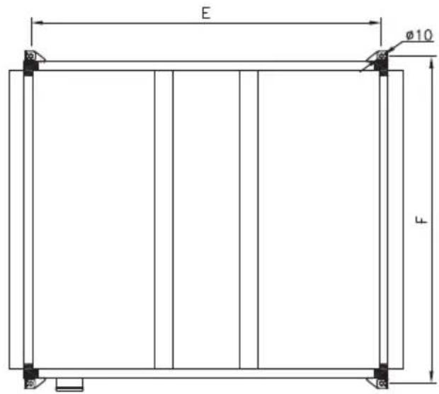


AIR DIRECTION

TERMINAL BOX MOTORS
| External Connections Supports | Weight (kg) | ||||||
| Model A B C D E F | |||||||
| UTBS-2 | 750 | 360 | 690 | 300 | 1159 | 790 86 | |
| UTBS-3 | 1100 | 410 | 1040 | 350 | 1159 | 1140 | 118 |
| UTBS-5 | 1500 | 410 | 1440 | 350 | 1159 | 1540 | 174 |
| UTBS-8 | 1900 | 500 | 1840 | 440 | 1159 | 1940 | 218 |
Long version: F7 filter with additional filter mounting capacity
Configuration with electric coil

P: Prefilter G4/M5 (accessory)
F: Filter F7
E: Electrical coil (E4,5 to E45)


AIR DIRECTION

TERMINAL BOX MOTORS
| External Connections Supports | Weight (kg) | |||||
| Model A B C D E F | ||||||
| UTBS-2 | 750 | 360 | 690 | 300 | 1159 | 790 86 |
| UTBS-3 | 1100 | 410 | 1040 | 350 | 1159 | 1140 118 |
| UTBS-5 | 1500 | 410 | 1440 | 350 | 1159 | 1540 174 |
| UTBS-8 | 1900 | 500 | 1840 | 440 | 1159 | 1940 218 |
Short version: Single filter type M5
Configuration with hot water coil

F: Filter M5
H2/H4: Hot water coil (2 rows / 4 rows)
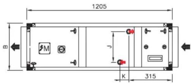
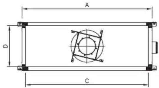

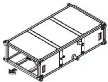

AIR DIRECTION

TERMINAL BOX MOTORS
External Conections Supports Coils Weight (kg)
| Model A B C D E F J K (H2/H4) Connections H2 H4 | ||||||||||||
| UTBS-2 | 750 | 360 | 690 | 300 | 1159 | 790 | 219 | 50 | 80 | 1-1/4" | 97 | 100 |
| UTBS-3 | 1100 | 410 | 1040 | 350 | 1159 | 1140 | 269 | 50 | 80 | 1-1/4" | 131 | 135 |
| UTBS-5 | 1500 | 410 | 1440 | 350 | 1159 | 1540 | 269 | 50 | 80 | 1-1/4" | 188 | 204 |
| UTBS-8 | 1900 | 500 | 1840 | 440 | 1159 | 1940 | 344 | 50 | 80 | 1-1/2" | 233 | 245 |
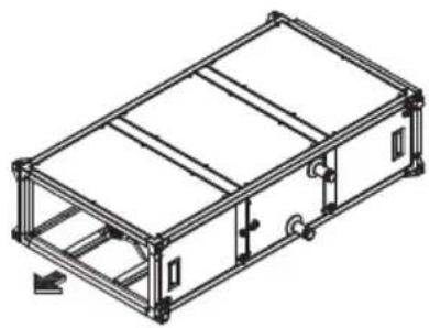
Long version: F7 filter with additional filter mounting capacity
Configuration with hot water coil

P: Prefilter G4/M5 (accessory)
F: Filter F7
H2/H4: Hot water coil (2 rows / 4 rows)

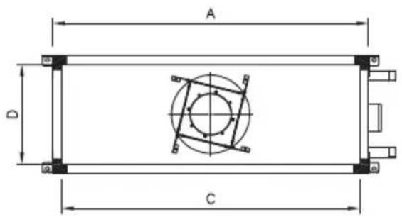


AIR DIRECTION

TERMINAL BOX MOTORS

HOT WATER INLET

HOT WATER OUTLET
External Conections Supports Coils Weight (kg)
| Model A B C D E F J K (H2/H4) Connections H2 H4 | ||||||||||||
| UTBS-2 | 750 | 360 | 690 | 300 | 1409 | 790 | 219 | 50 | 80 | 1-1/4" | 97 | 100 |
| UTBS-3 | 1100 | 410 | 1040 | 350 | 1409 | 1140 | 269 | 50 | 80 | 1-1/4" | 131 | 135 |
| UTBS-5 | 1500 | 410 | 1440 | 350 | 1409 | 1540 | 269 | 50 | 80 | 1-1/4" | 188 | 204 |
| UTBS-8 | 1900 | 500 | 1840 | 440 | 1409 | 1940 | 344 | 50 | 80 | 1-1/2" | 233 | 245 |
Short version: Single filter type M5
Configuration with cold water coil
![graph TD A[" "] --> B["C4"] B --> C["C6"] C --> D[" "] style C4 fill:#f9f,stroke:#333 style C6 fill:#bbf,stroke:#333](/content/2026/05/987157/images/e6b9d3e87e4b52444ec8f236bdbaa6742a1b4dbbab99ddba0527698ba547a275.jpg)
F: Filter M5
C4/C6: Cold water coil (4rows/6rows)



SENTIDO AIRE
AIR DIRECTION

TERMINAL BOX MOTORS

COLD WATER INLET
COLD WATER OUTLET
CONDENSATE OUTLET 3/4"
External Connections Supports Coils Weight (kg)
| Model A B C D E F J K (C4/C6) Connections C4 C6 | ||||||||||||
| UTBS-2 | 750 360 | 690 300 | 1159 | 790 219 | 80 120 | 1-1/4" | 105 107 | |||||
| UTBS-3 | 1100 | 410 | 1040 | 350 | 1159 | 1140 | 269 | 80 | 120 | 1-1/4" | 142 | 147 |
| UTBS-5 | 1500 | 410 | 1440 | 350 | 1159 | 1540 | 269 | 80 | 120 | 1-1/4" | 204 | 210 |
| UTBS-8 | 1900 | 500 | 1840 | 440 | 1159 | 1940 | 344 | 80 | 120 | 1-1/2" | 258 | 268 |
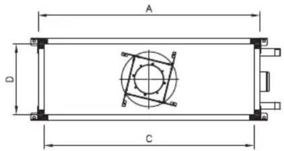
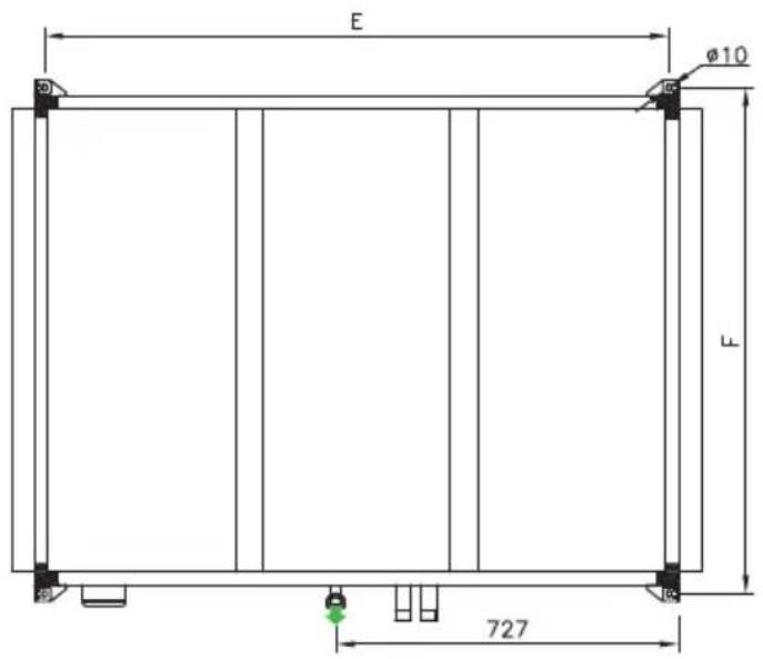
Long version: F7 filter with additional filter mounting capacity
Configuration with cold water coil
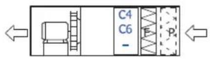
P: G4/M5 prefilter (accessory)
F: Filter F7
C4/C6: Cold water coil (4rows/6rows)

P: G4/M5 prefilter (accessory)
F: Filter F7
C4/C6: Cold water coil (4rows/6rows)
E: Electrical battery (E4,5 to E45)



AIR DIRECTION

TERMINAL BOX MOTORS

COLD WATER INLET

COLD WATER OUTLET

CONDENSATE OUTLET 3/4"
External Connections Supports Coils Weight (kg)
| Model A B C D E F J K (C4/C6) Connections C4 C6 | ||||||||||||
| UTBS-2 | 750 360 | 690 300 | 1409 | 790 219 | 80 120 | 1-1/4" | 105 107 | |||||
| UTBS-3 | 1100 | 410 | 1040 | 350 | 1409 | 1140 | 269 | 80 | 120 | 1-1/4" | 142 | 147 |
| UTBS-5 | 1500 | 410 | 1440 | 350 | 1409 | 1540 | 269 | 80 | 120 | 1-1/4" | 204 | 210 |
| UTBS-8 | 1900 | 500 | 1840 | 440 | 1409 | 1940 | 344 | 80 | 120 | 1-1/2" | 258 | 268 |
Short version: Single filter type M5
Configuration with cold water coil C4 and hot water coil H2

F: M5 filter
H2: Hot water coil (2 rows)
C4: Cold water coil (4 rows)

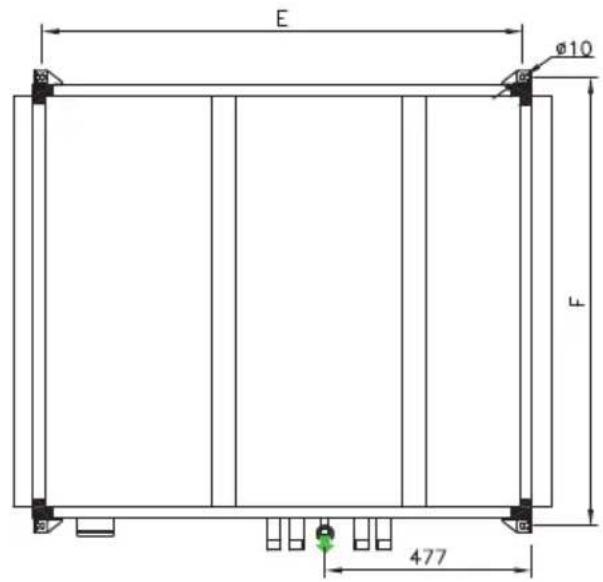
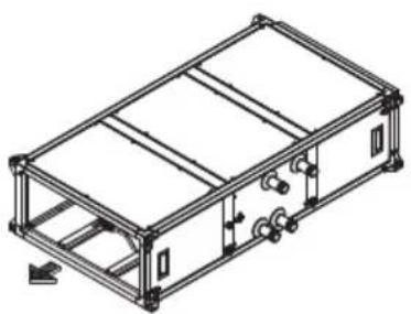
AIR DIRECTION
M TERMINAL BOX MOTORS
HOT WATER INLET
C→ HOT WATER OUTLET
COLD WATER INLET
COLD WATER OUTLET
CONDENSATE OUTLET 3/4"
| External Connections Supports Coils | Weight(kg) | |||||||||
| Model A B C D E F J Connections C4 / H2 | ||||||||||
| UTBS-2 750 360 690 300 1159 790 219 1-1/4" 1-1/4" 111 | ||||||||||
| UTBS-3 1100 410 1040 350 1159 | 1140 269 1-1/4" 1-1/4" 151 | |||||||||
| UTBS-5 1500 410 1440 350 1159 | 1540 269 1-1/4" 1-1/4" 216 | |||||||||
| UTBS-8 1900 500 1840 440 1159 | 1940 344 1-1/2" 1-1/2" 272 | |||||||||
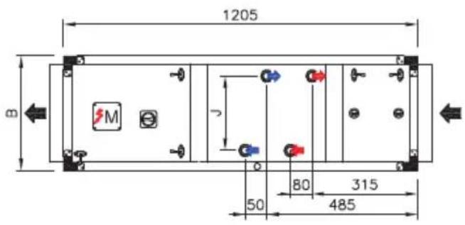
Long version: F7 filter with additional filter mounting capacity
Configuration with cold water coil C4 and hot water coil H2
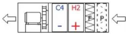
P: G4/M5 prefilter (accessory)
F: F7 filter
H2: Hot water coil (2 rows)
C4: Cold water coil (4 rows)


AIR DIRECTION
M TERMINAL BOX MOTORS
HOT WATER INLET
HOT WATER OUTLET
COLD WATER INLET
COLD WATER OUTLET
CONDENSATE OUTLET 3/4"
| External Connections Supports Coils | Weight (kg) | |||||||||
| Model A B C D E F J Connections C4 / H2 | ||||||||||
| UTBS-2 750 360 690 300 1409 790 219 1-1/4" 1-1/4" 111 | ||||||||||
| UTBS-3 1100 410 1040 350 1409 | 1140 269 1-1/4" 1-1/4" 151 | |||||||||
| UTBS-5 1500 410 1440 350 1409 | 1540 269 1-1/4" 1-1/4" 216 | |||||||||
| UTBS-8 1900 500 1840 440 1409 | 1940 344 1-1/2" 1-1/2" 272 | |||||||||
Short version: Single filter type M5
Configuration with cold water coil C6 and hot water coil H2

F: M5 filter
H2: Hot water coil (2 rows)
C6: Cold water coil (6 rows)


AIR DIRECTION
M TERMINAL BOX MOTORS
HOT WATER INLET
HOT WATER OUTLET
COLD WATER INLET
COLD WATER OUTLET
CONDENSATE OUTLET 3/4"
| External Connections Supports Coils | Weight(kg) | |||||||||
| Model A B C D E F J Connections C6 / H2 | ||||||||||
| UTBS-2 750 360 690 300 1159 790 219 1-1/4" 1-1/4" 113 | ||||||||||
| UTBS-3 1100 410 1040 350 1159 | 1140 269 1-1/4" 1-1/4" 156 | |||||||||
| UTBS-5 1500 410 1440 350 1159 | 1540 269 1-1/4" 1-1/4" 222 | |||||||||
| UTBS-8 1900 500 1840 440 1159 | 1940 344 1-1/2" 1-1/2" 282 | |||||||||
Long version: F7 filter with additional filter mounting capacity
Configuration with cold water coil C6 and hot water coil H2
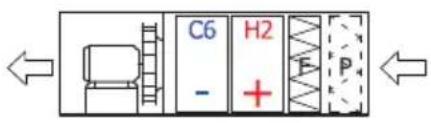
P: G4/M5 prefilter (accessory)
F: F7 filter
H2: Hot water coil (2 rows)
C6: Cold water coil (6 rows)


AIR DIRECTION
M TERMINAL BOX MOTORS
HOT WATER INLET
C→ HOT WATER OUTLET
COLD WATER INLET
COLD WATER OUTLET
CONDENSATE OUTLET 3/4"
| External Connections Supports Coils | Weight(kg) | |||||||||
| Model A B C D E F J Connections C6 / H2 | ||||||||||
| UTBS-2 750 360 690 300 1409 790 219 1-1/4" 1-1/4" 113 | ||||||||||
| UTBS-3 1100 410 1040 350 1409 | 1140 269 1-1/4" 1-1/4" 156 | |||||||||
| UTBS-5 1500 410 1440 350 1409 | 1540 269 1-1/4" 1-1/4" 222 | |||||||||
| UTBS-8 1900 500 1840 440 1409 | 1940 344 1-1/2" 1-1/2" 282 | |||||||||
Short version: Single filter type M5
Configuration with direct expansion coil
![graph LR A["Input"] --> B["Processing Unit"] B --> C["X4"] B --> D["X6"] C --> E["Output"] D --> E](/content/2026/05/987157/images/0a2d19e1f310e66705b355eca4e88e629d9f066c4760805df93c8561689fff66.jpg)
F: M5 filter
X4/X6: Direct expansion coil (4 rows / 6 rows)
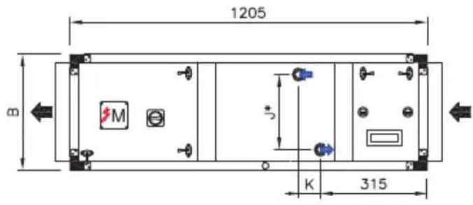


AIR DIRECTION

TERMINAL BOX MOTORS

REFRIGERANT INLET

REFRIGERANT OUTLET

CONDENSATE OUTLET 3/4"
| External Connections Supports | Coils | Weight (kg) | ||||||||||||
| J | K(X4/X6) | Inlet Connection(X4/X6) | Outlet Connection(X4/X6) | |||||||||||
| Model A | B | C | D | E | F | C4 | C6 | |||||||
| UTBS-2 | 750 | 360 | 690 | 300 | 1159 | 790 | 232 | 80 | 120 | 3/8" | 1/2" | 5/8" | 5/8" | 105 |
| UTBS-3 | 1100 | 410 | 1040 | 350 | 1159 | 1140 | 280 | 80 | 108 | 1/2" | 1/2" | 5/8" | 5/8" | 142 |
| UTBS-5 | 1500 | 410 | 1440 | 350 | 1159 | 1540 | 280 | 80 | 100 | 1/2" | 1/2" | 5/8" | 3/4" | 204 |
| UTBS-8 | 1900 | 500 | 1840 | 440 | 1159 | 1940 | 355* | 55 | 120 | 1/2" | 2 x 1/2" | 5/8" | 2 x 3/4" | 258 |
* On the UTBS-8 model with coil X6 the coil is two-stage (double inlet and outlet connection).
Long version: F7 filter with additional filter mounting capacity
Configuration with direct expansion coil
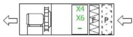
P: G4/M5 prefilter (accessory)
F: F7 filter
X4/X6: Direct expansion coil (4 rows / 6 rows)
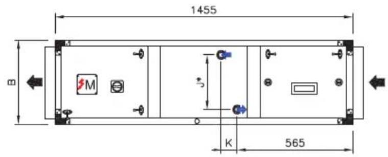
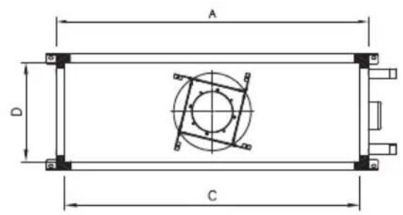
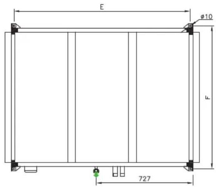
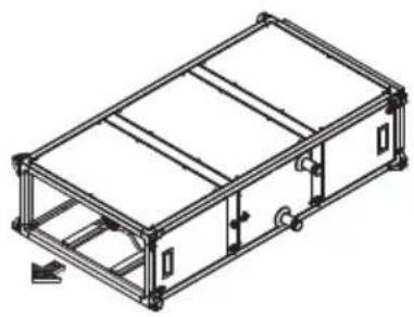

AIR DIRECTION

TERMINAL BOX MOTORS

REFRIGERANT INLET

REFRIGERANT OUTLET

CONDENSATE OUTLET 3/4"
| Coils | |||||||||||||||
| J K (X4/X6) Inlet | Connection(X4/X6) | Outlet Connection(X4/X6) | Weight (kg) | ||||||||||||
| Model A | B | C | D | E | F | C4 | C6 | ||||||||
| UTBS-2 | 750 | 360 | 690 | 300 | 1409 | 790 | 232 | 80 | 120 | 3/8" | 1/2" | 5/8" | |||
| UTBS-3 | 1100 | 410 | 1040 | 350 | 1409 | 1140 | 280 | 80 | 108 | 1/2" | 1/2" | 5/8" | |||
| UTBS-5 | 1500 | 410 | 1440 | 350 | 1409 | 1540 | 280 | 80 | 100 | 1/2" | 1/2" | 5/8" | |||
| UTBS-8 | 1900 | 500 | 1840 | 440 | 1409 | 1940 | 355* | 55 | 120 | 1/2" | 2 x 1/2" | 5/8" | |||
* On the UTBS-8 model with coil X6 the coil is two-stage (double inlet and outlet connection).
7.4.2. Space for maintenance
The UTBS can be ordered with access side in the desired hand (according to air sense) Access to filters can by done throw the specific lateral registers or from the inferior panels. The access to the electrical cabinet is from the lateral panel.
To perform the disassembly of coils and batteries, it is necessary to remove the lateral panel and slide the battery until her complete extraction.

L Versions
Left Connection side according to air sense


R versions
Right connection side according to air sense


Access to filters, control box and water coils connections (if exist)

Access to filters and motors

Access to motors
| Model | W | H | A | |
| UTBS-2 750 360 500 850 | ||||
| UTBS-3 1100 410 500 1200 | ||||
| UTBS-5 1500 410 500 1600 | ||||
| UTBS-8 1900 500 500 2000 |
- For ceiling and floor-mounted applications, the unit must be suspended from the four angle brackets on each module, as follows:
CEILING MOUNTED FLOOR MOUNTED

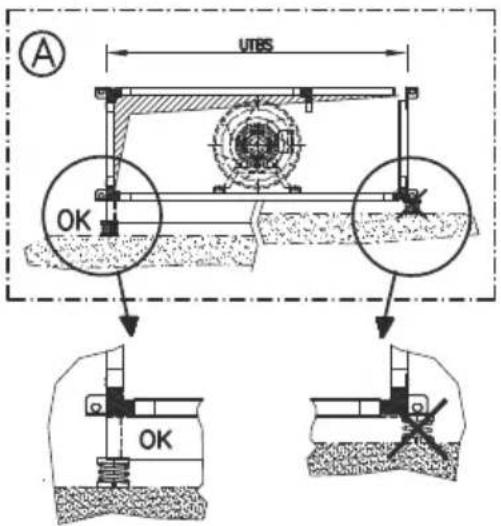
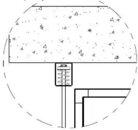
To prevent transmission of motor vibrations until wrought, it is necessary to install antivibrations on each of the anchor points. Use antivibration kits recommended in the following table:
| Model Antivibration support Quantity per | UTBS | Nominal load (Kg) | Vertical displacement (mm) |
| UTBS-2 AM. DE MUELLE TM-50 4 50 21-27 | |||
| UTBS-3 AM. DE MUELLE TM-50 4 50 21-27 | |||
| UTBS-5 AM. DE MUELLE TM-75 4 75 21-27 | |||
| UTBS-8 AM. DE MUELLE TM-100 4 100 21-27 |
WARNING! Due to the length and weight of the units, each module must be suspended separately.
MOUNTING POSITION

Before switch on the unit, verify that the duct system is free of obstacles to prevent or modify the air circulation.
7.5. ASSEMBLING THE MODULES
Exist different accessories that can be supplied with UTBS module:

| Model Flexible connection Sound attenuator | Antivibrations support Visor Damper module Actuator (4 units) | 24V |
| UTBS-2 JF-UTBS 650x250 SIL-2 750 AM. DE MUELLE TM-50 VF UTBS-2 ID KIT COMP. UTBS-2 | LF 24 S | |
| UTBS-3 JF-UTBS 1000x300 SIL-3 750 AM. DE MUELLE TM-50 VF UTBS-3 ID KIT COMP. UTBS-3 | ||
| UTBS-5 JF-UTBS 1400x300 SIL-5 750 AM. DE MUELLE TM-75 VF UTBS-5 ID KIT COMP. UTBS-5 | ||
| UTBS-8 JF-UTBS 1800x400 SIL-8 750 AM. DE MUELLE TM-100 VF UTBS-8 ID KIT COMP. UTBS-8 |
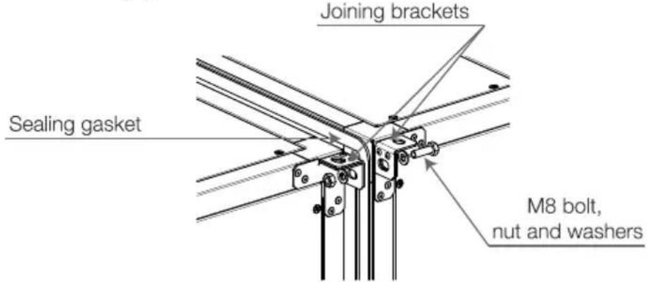
The module frames have mounting brackets on each corner that are used to secure the equipment to the ceiling and to join the various modules to one another. If the unit is made up of different modules, it will be supplied with a joining kit with 4 sets of bolts, washers, nuts and a sealing gasket.
7.5.1. Move the fl ange from the main module to the accessory module

UTBS Module delivered with fl anges mounted.

Remove the fl ange on the side where the accessory module will be mounted.
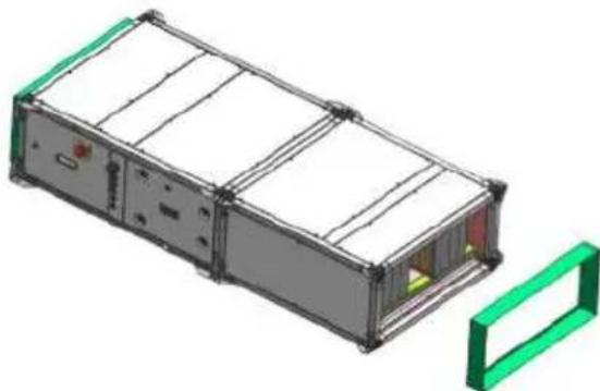
Over the accessory, mount the fl ange (previously retired from UTBS module).

The result is an assembly of two modules with inlet and outlet fl anges:
- Silencer with inlet fl ange
- UTBS Module with outlet fl ange
7.5.2. Additional filters mounting
The air conditioner is supplied with a filter mounted inside. In the long frame versions, equipped with F7 filter from factory it is also possible to mount a second filter in the specific gap (order as accessory).
See chapter "Filter replacement" for information about the way to access filter section depending on the unit type.
7.5.3. Assembling fl exible connections
- If you have ordered flexible connections for the ends of the units, they will be supplied separately.

7.5.4. Mixing module installation
The mixing module is installed in the intake air side and allows to realize the the mixing between the outdoor air and the recirculated air with proportional regulation of existent dampers in either air intakes.
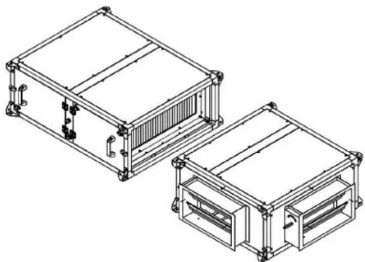
The mix module and the corresponding servomotors are supplied both as accessories. The installer should mount the damper module, using the screws and bolts supplied with the unit. After that, mount the servomotor on the damper shaft. Once mounted the servomotor, make the electrical connection between the servomotor and the electrical cabinet according to the indications in the electrical diagram.
Check that the rotation sense of the actuator is correct. If it is necessary, modify the damper rotation sense via the selector in the frontal of the actuator

7.5.5. Installation with isolation damper
To realise the unit isolation of the ductwork, each time that the unit is stopped, it is possible to install one isolation damper in the unit inlet:
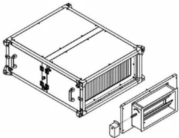
Both the damper module and the corresponding servomotors are supplied as accessories. The installer should mount the damper module, using the supplied hardware with this. Mount the servomotor on the damper shaft.
After mounting the servomotor, make the electrical connection to the electrical cabinet according the electrical diagram.
Check that the actuator sense of rotation is correct (once the unit is stopped the damper must be closed). If it is necessary, modify the damper rotation sense via the selector in the frontal of the actuator

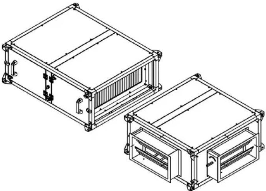
- Air 3 inlet section: It is sent with a fixed position of the dampers. If not coincide with the needs of the installation, change the frontal panel as shown.
7.6. CONNECTING THE UNIT TO THE WATER NETWORK
- Maximum pressure: 10 bar
- Maximum temperature: 100°C
- Minimum temperature: -20°C with the appropriate mixture of antifreeze
- For heat exchangers with threaded connections, secure the coil manifold with the appropriate tool when tightening the threads. This will prevent the force from being transmitted to the manifold, which can damage it.

- The following table gives a list of the types of thread for each UTBS:
| MODEL THREAD | |
| UTBS-2 (2, 4 or 6 -pipes) | 1-1/4" |
| UTBS-3 (2, 4 or 6 -pipes) | 1-1/4" |
| UTBS-5 (2, 4 or 6 -pipes) | 1-1/4" |
| UTBS-8 (2, 4 or 6 -pipes) | 1-1/2" |
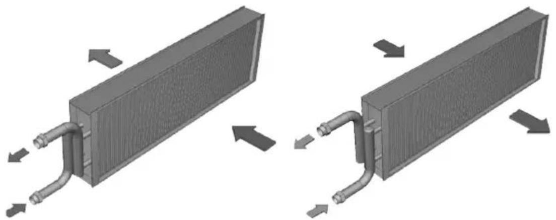
- The water coils must run counter to the flow of air to provide the correct performance. This means that the fluid inlet must be connected on the manifold located on the air outlet side, and the fluid outlet must be connected on the manifold situated on the air intake side, as shown in the following illustrations:
- We suggest having all the elements needed for the installation on hand, mentioning the following devices in particular:
- Unit intake pre-filter that traps suspended particulate matter.
- Bleed valves should be fitted at each of the high points in the installation to maintain good water circulation.
- It is recommended to keep water in the hydraulic system at all times (install an auto-filler valve and pressure switches that send an alarm and shut off power to the equipment, etc.)
- Check to make sure that the flow of water circulating through the unit is appropriate.
- Shut-off valves must be installed at each connection on the water line to allow the unit to be isolated if necessary (to clean filters, make repairs, replace parts etc.) and avoid the need to completely drain the water circuit.
- Anti-vibration bellows should be installed at the inlet and outlet from the unit to prevent the transmission of vibrations that could result in damage to the heat exchanger coils due to excess stress on the circuits.
7.7. CONNECTING THE UNIT TO THE DUCT SYSTEM
- Never use the unit as a support or weight-bearing structure for ductwork.
- Connect the unit to the air ducts using flexible connectors to prevent vibrations from being transmitted to the duct system.
- Check to make sure air intake and flow are not being blocked and that there are no obstacles impeding good air circulation. Failure to do so will affect the efficiency of the system.
VERY IMPORTANT:
In the manufacturing process of the panels, fi lters and batteries, protective products are used to increase corrosion protection. During the fi rst hours of operation after the unit commissioning, especially in those units equipped with heating stage, unpleasant smells could be produced.
7.8. DIRECT EXPANSION COILS CONNECTION (DX)
Coil characteristics
DX 4 rows coil
For applications with 100% recirculated air
| UTBS Volume (L) | Phases Tubes Rows Circuits ∅ Liquid | header (mm) | ∅ Gaz header (mm) | Cooling power (kW) | Heating power (kW) | Airfl ow (m3/h) | ||||
| UTBS-2 1,2 1 10 4 2 1/2" (13mm.) 3/4" (19mm.) 4,6 4,9 1.250 | ||||||||||
| UTBS-3 2,21 1 12 4 4 5/8" (16mm.) 3/4" (19mm.) 8,8 8,0 2.500 | ||||||||||
| UTBS-5 | 2,41 | 1 | 12 | 3 | 5 | 5/8" (16mm.) | 3/4" (19mm.) | 10,9 | 10,0 | 3.500 |
| UTBS-8 | 4,4 | 1 | 15 | 3 | 7 | 5/8" (16mm.) | 3/4" (19mm.) | 19,9 | 17,2 | 6.000 |
DX 6 rows coil
For applications with 50% outdoor air/ 50% recirculated air
| UTBS Volume (L) | Phases Tubes Rows Circuits ∅ Liquid | header (mm) | ∅ Gaz header (mm) | Cooling power (kW) | Heating power (kW) | Airfl ow (m3/h) | ||||
| UTBS-2 | 2 | 1 | 10 | 6 | 5 | 5/8" (16mm.) | 3/4" (19mm.) | 10,0 | 10,5 | 1.250 |
| UTBS-3 | 3,31 | 1 | 12 | 5 | 6 | 5/8" (16mm.) | 3/4" (19mm.) | 19,4 | 19,9 | 2.500 |
| UTBS-5 | 4,3 | 1 | 12 | 5 | 9 | 5/8" (16mm.) | 7/8" (22mm.) | 26,6 | 27,6 | 3.500 |
| UTBS-8 | 8,4 | 2 | 15 | 6 | 10+10 | 5/8" (16mm.) | 7/8" (22mm.) | 47,8 | 49,8 | 6.000 |
Installation recommendations
In units that incorporate direct expansion coils it is necessary to consider the following installation recommendations:
- The rigidity and stability of the installation ducts, should be ensured using, if necessary, expansion joints and antivibration elements, avoiding the generation of stress due to the transmission of vibrations to the distributor and suction headers.
- When making the refrigerant circuits, allow free space enough to allow a right access for maintenance tasks.
- The connection to the suction line (liquid) should be done from the smaller diameter manifold (recognizable because of the distributor), The gas line has to be connected to suction header (larger diameter manifold).

- The dimensioning and manufacture of the refrigerant installation must be performed by qualified personnel with specific training in refrigeration techniques (authorized installers), paying particular attention to:
- Evaporative coils are supplied with sealed ends without refrigerant charge or nitrogen load.
- The cooling pipe used in the installation must be copper suitable for its use in cooling circuits.
- Before filling with refrigerant, cleaned dehydration and deoxidized of the entire refrigerant circuit must be done.
- Both ends of the batteries (sealed points) must be cut before being welded to the refrigeration installation pipe.
- The circuit must be equipped with all the necessary components to ensure functionality and proper functioning of the entire DX system (compressor, condenser, expansion valve operation control kit, filter, desiccant, etc...).
In order to ensure oil return to the compressor, it is recommended to design the suction and gas lines, such that flow speeds of 2,6 m/s (horizontal pipes) and 5,2 m/s (vertical pipes) will be achieved.
7.9. DRAINAGE SYSTEM
- A siphon must be installed with pressure head difference in mmWG greater than the pressure provided by the fan, to facilitate draining condensate from the tray.

- The drainage system should have a minimum slope of 2% .
7.10. ELECTRICAL CONNECTION
- The unit installation must be done by a qualified professional.
- Before putting the unit in place, make sure that the nominal supply voltage matches that listed on the unit's identification plate.
- It should be installed with cables whose cross-section meets current regulations and prevents overheating and voltage drops that exceed permissible limits. Current regulations must be obeyed, and the designer's instructions must be followed at all times.
- Before connecting the cables, make sure that the electricity is turned off and that there is no voltage present in any of them.
- The unit installation must meet the following regulations:
- Low Voltage Directive 2006/95/CE
- Machinery Directive 2006/42/CE
- Electromagnetic Compatibility 2004/108/CE
- The instructions in current regulations regarding the protection of electrical lines against defects and direct and indirect contact must be obeyed at all times.
- After these steps are performed, check to make sure all electrical connections are secure (loose wiring connections can cause irreparable damage).
- Check to make sure the electrical resistance between earth and any electrical terminal is greater than 1 megohms. If it is not, do not start up the unit until the electrical short has been located and repaired.
- As a safety measure, if there is no power to the fan, the necessary interlocks must be performed so that all other electrical components are also de-energised.
7.11. TEMPERATURE PROBES LOCATION
The UTBS-PRO-REG units are with the air temperature probes wired to the electrical board.
All the versions include 3 different temperature probes to manage air heating and/or cooling demand:
- TSUP : Supply air temperature. Mounted at the UTBS module air outlet. Factory wired, this probe is used to control the supply air temperature. This sensor should not be manipulated.
- TODA : Outdoor air temperature. This probe is delivered inside the electric cabinet (coiled itself). Although the probe is factory wired to the PCB controller, the installer must fit the sensor inside the duct system depending on the type of installation performed.
- TETA : Extract air temperature. This probe is delivered inside the electric cabinet (coiled itself). Although the probe is factory wired to the PCB controller, the installer must fit the sensor inside the duct system depending on the type of installation performed.
Outdoor air (ODA) and Extract air (ETA) temperature probes are 4m length, allowing that each probe will be mounted in the desired position.
IMPORTANT: Regardless of the type of installation performed, the three air probes must always be wired to the control cabinet. If any of the temperature probes is missing, it will cause the unit malfunction as well as the alarm message on the controller display.
During the unit installation, the installer should retire the temperature probes from into the electrical cabinet and fit them in the definitive position according depending on the operation mode.
Detail of the location of the Outdoor Air temperature probe ( TODA ) and the Extract Air temperature ( TETA ) depending on the type of installation:
Installation with 100% of Outdoor Air

Installation with 100% of Indoor Air (Recirculation)

Installation with mixing module (Variable % Outdoor Air / Indoor Air)

Those versions with internal hot water coil or reversible coil included, also integrate a water temperature probe mounted on the coil return manifold. This probe, which is supplied already assembled and wired from factory, supervises the risk of freezing. Do not manipulate this probe in any case.
8. START-UP PROCEDURE
IMPORTANT: Before access the unit, it is obligatory to switch off the electrical supply by means of the general switch placed in the cabinet box.
- All access panels on the unit must be closed before starting.
- Make sure that the earth connection is securely connected.
- First turn on the water circulation pump. Wait several minutes to make sure the flow of circulation remains steady and that there is no variation in the flow. Make sure that any air bubbles have been drawn to the bleed points and that they have been bled off.
- Make sure that the pressures in the unit do not exceed the maximum pressure for the exchanger coils.
- Continue to run the circulation pump for at least 2 hours. Turn off the pump and then remove the filter from the unit. To do so, close the appropriate shut-off valves to prevent the water line from emptying, and to prevent air from getting in. Then clean the filter.
- Take a careful look at the particles trapped in the filter. Make sure that these particles are not coming from a source that will clog the filter again (such as pipe scale from iron pipes, hard water deposits, etc.).
- Re-insert the filter, bleed the air from the system and turn the circulation pump on again. Wait several more minutes to make sure that the flow of water remains steady and there is no variation in the flow. If good water circulation is not achieved, repeat the steps described above.
- Before turning on the power to the unit, check to make sure that nothing is hindering the movement of the regulator dampers if these are operated using a servomotor.
- If the damper are manually operated, make sure by manually tightening the control that they cannot be closed due to the force of air or anything else while the unit is running.
- Turn on the external main power switch to the unit, keeping the control switch in the off position. After that, check to make sure the input voltage at the unit's electrical terminals matches the one indicated on the identification plate (the minimum voltage will be 10% below the rated voltage indicated on the identification plate).
- Do not start up the fan if the duct network is not completely closed, since turning on the fan with no load can cause over-currents that cause wear to the motor. This can also occur if the static pressure demanded is greater than the pressure losses that occur in the duct network. To fix this, close the flow regulator dampers so that there is a greater pressure loss.
- Test the total current drawn by the unit as a whole, also checking to make sure there are no phase lags between the currents on the different lines.
The UTBS PRO-REG units are supplied with integrated electronic control in the unit. It allows to perform the following functions:
| Without batteries | With water coils | With electrical battery | Witch DX coil | |
| MAIN COMPONENTS | ||||
| General proximity switch over the electrical box • • • • | ||||
| Fresh air temperature probe - • • • | ||||
| Extract air temperature probe - • • • | ||||
| Supply air temperature probe - • • • | ||||
| Defrost temperature probe • | ||||
| CHANGE OVER thermostat to be installed on the water supply coil | - | 0 | - | |
| 3 way valve with proportional 0-10V actuator 3WV PROP 24V | - | 0 | - | |
| Air flow transmitter • • • • | ||||
| Clogged filters switch • • • • | ||||
| FEATURES | ||||
| ON/OFF function (Remote ON/OFF via external power free contact) | • | • | • | |
| Automatic airflow adjustment, according to time band (internal Timer) | • | • | • | |
| Flow control in CAV mode. Constant airflow regardless of the state of fouling of the filters | • | • | • | |
| Automatic airflow adjustment in VAV mode, according to external signal 0-10V (CO2 accessory) | • | • | • | |
| Automatic speed adjustment of the fans in Constant Pressure mode (Increase of fan speed when pressure in the duct system decreases). It is necessary TDP-S accessory | • | • | • | |
| BOOST function (Forced speed preset via external power free contact) | • | • | • | |
| Regulation of water coil thermal power. 0-10V control of the water valve (accessory) | - | • | - | |
| Regulation of electric heater battery thermal power. Proportional control via SSR | - | - | • | |
| Proportional control of thermal demand (0-10V output signal) to manage expansion valve kit (verify compatibility with used DX control valve kit) | - | - | - | |
| Isolation damper control (accessory) | • • • • | |||
| Operation of an external mixing box (accessory) | • • • - | |||
| Speed-control of an external fan (slave) with analogic signal 0-10V available | • | • | • | |
- included; O optional; - Non available
| Without batteries | With water coils | With electrical battery | Witch DX coil | |
| SUPERVISION | ||||
| Control of polluted filters via pressure switches (included) • • • • | ||||
| Failure in temperature probes • • • • | ||||
| Failure in fan via pressure switches (included) • • • • | ||||
| Anti-frost protection of water coils - • - - | ||||
| Alarm display • • • • | ||||
| COMMUNICATION | ||||
| Control via touch-screen included • • • • | ||||
| Modbus RTU (RS-485) • • • • | ||||
| BACNET TCP/IP • • • • |
- included; O optional; - Non available
Version with electric batteries
![graph LR A["Input"] --> B["Process Unit"] B --> C["ACCESSORY ID SM"] C --> D["PF"] D --> E["F"] E --> F["E"] F --> G["AS"] G --> H["SF"] H --> I["S1"] I --> J["ACCESSORY TDP SCO2 EF"] I --> K["ACCESSORY TDP SCO2 EF"] L["RT"] --> M["User Interface"] M --> N["PR1"] M --> O["PR2"] P["CSR"] --> F](/content/2026/05/987157/images/eae230011cd850c93d87c3266ce8175e5586742d4cc0933d3d05595609d89c9c.jpg)
![graph TD A["Input"] --> B["SM"] C["Input"] --> D["SM"] B --> E["SM"] D --> E E --> F["F"] F --> G["E"] G --> H["SF"] H --> I["S1"] I --> J["EF"] G --> K["AS"] K --> L["TF"] M["RT"] --> N["Accessory"] O["PF"] --> P["FF"] Q["Pr1"] --> R["SSR"] S["Pr2"] --> R T["ACCESSORY"] --> U["TDP"] T --> V["SCO2"]](/content/2026/05/987157/images/3c939c56f23d32b478549064c0a6686e9f06967a5513a05b22694814197e66c5.jpg)
SF Supply fan
SSR Electrical heater proportional regulator
E Electrical heater
S1 Supply air temperature probe
S2 External air temperature probe
S3 Return air temperature probe
PF Filter clogging detector (Pressure switch)
S1 Supply aire temperature probe
AS Air flow sensor
RT Remote hand terminal
EF External Fan (slave mode)
F Filter
Pr1/Pr2 Safety Thermostat (Manual/Auto)
SCO2 CO2 Sensor (Accessory)
TDP Pressure transmitter TDP-S (Accessory)
ID Isolation Damper (Accessory)
MB Mixing box (Accessory)
SM Damper servo-motor (Accessory)
Versions with hot and/or cold water coils
![graph TD A["Sensor"] --> B["S2/S3"] B --> C["ID"] C --> D["SM"] D --> E["F"] E --> F["PrF"] F --> G["HC"] G --> H["CC"] H --> I["AS"] I --> J["SF"] J --> K["S1"] K --> L["RF"] L --> M["ACCESSORY"] N["RT"] --> O["Accessory"] P["HV"] --> Q["Switch"] R["CV"] --> S["Switch"] T["PF"] --> U["Switch"] V["A…](/content/2026/05/987157/images/b773ae5bb29efce0df51f793d964ddd3777ca1242862127fab113cb3383a2434.jpg)
![graph TD A["Engine"] --> B["SM"] C["Engine"] --> D["SM"] B --> E["MB"] D --> E E --> F["PF"] F --> G["F"] G --> H["PrF"] H --> I["HC"] I --> J["CC"] J --> K["AS"] K --> L["SF"] L --> M["S1"] M --> N["ACCESSIONARY"] N --> O["TDP"] N --> P["SCO2"] Q["RT"] --> R["HV"] R --> S["CV"] T["ACCESSORY"] --> U…](/content/2026/05/987157/images/59204f17b7f166a21b4a613cf8ad5df4e3e265792df9ade7e4d9bec932db8ddb.jpg)
| SF | Supply fan | RT | Remote hand terminal | PrF | Freeze protection |
| PF | Filter clogging detector (Pressure switch) | EF | External Fan (slave mode) | ID | Isolation Damper (Accessory) |
| S1 | Supply air temperature probe | F | Filter | MB | Mixing box (Accessory) |
| S2 | External air temperature probe | HC | Heating coil | SM | Damper servo-motor (Accessory) |
| S3 | Return air temperature probe | CC | Cooling coil | SCO2 | CO2 Sensor (Accessory) |
| AS | Air flow sensor | HV | Heating regulation valve | TDP | Pressure transmitter TDP-S (Accessory) |
| CV | Cooling regulation valve |
Versions with reversible water coil
![graph LR A["Light Bulb"] --> B["Process Unit"] B --> C["ID"] C --> D["SM"] D --> E["PF"] E --> F["F"] F --> G["RC"] G --> H["SF"] H --> I["S1"] I --> J["EH"] K["RF"] --> L["Device"] M["RT"] --> N["Device"] O["ChO"] --> P["HCV"] Q["ACCESSORY"] --> R["+/- RC"] S["ACCESSORY"] --> T["AC/DC Controller"]…](/content/2026/05/987157/images/241d00e56fe5582f3b41c035c0680847c6e9933b39aa4a2922c2c43d867ad106.jpg)
![graph TD A["Power Source"] --> B["Switch S2"] C["Power Source"] --> D["Switch S3"] B --> E["SM"] D --> F["SM"] E --> G["MB"] F --> G G --> H["PF"] H --> I["F"] I --> J["RC"] J --> K["AS"] K --> L["SF"] L --> M["S1"] M --> N["ACCESSIONY"] N --> O["TDP"] N --> P["SCO2"] Q["RT"] --> R["HCV"] R --> J st…](/content/2026/05/987157/images/cd26d008abf4eaf64f15921baa712254a8cae6d2e8430def77dce54b86d11fb3.jpg)
| SF | Supply fan | AS | Air flow sensor | ChO | Change Over Thermostat (Accessory) |
| PF | Filter clogging detector (Pressure switch) | RT | Remote hand terminal | ID | Isolation Damper (Accessory) |
| S1 | Supply air temperature probe | EF | External Fan (slave mode) | MB | Mixing box (Accessory) |
| S2 | External air temperature probe | F | Filter | SM | Damper servo-motor (Accessory) |
| S3 | Return air temperature probe | RC | Reversible coil | SCO2 | CO2 Sensor (Accessory) |
| HCV | Heating/cooling regulation valve | TDP | Pressure transmitter TDP-S (Accessory) |
11.1. CHANGE LANGUAGE
Before you start using the remote control, select the desired language.
To make the change, follow the following sequence:

11.2. SIMPLIFIED MENUS / ACCESSES
The unit has a quick access to the main functions.
Accesses: There are 3 access levels to the controller:
- User level (no password) – Access to the start/stop – auto or PV/GV functions and increase of the set point temperature (+/- 3°C).
- Operator level (password) – Access in read and write to adjustments and parameters, but no access to the system configuration.
- Master level (password) - Access in read and write to adjustments and parameters, as well as access to the system configuration.
11.2.1. User level
To adjust the temperature set point and the operation mode selection of the unit (use of the time program, stop the unit or possible forcing to a given speed).
These two temperatures and ventilation functions are accessible in two specific menus specially dedicated to this usage:
Adjustment the temperature setpoint

To modify the temperature is necessary to enter the code 1111.
Operating mode selection

In units with electrical, if the operation mode is changed while the fans are running, the unit will stop sequentially; first switching off the electrical heater, and after 2 minutes switching off the fans, then finally the unit will re-stard with the right working mode.
11.2.2. Installer level
In this level is possible to adjust the operating parameters of the unit: Fan, heating, display, errors, etc..
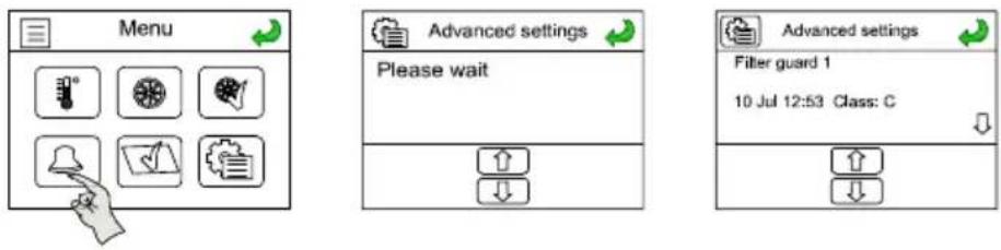
Alarm display
Screen display settings
Adjust the brightness and display feedback.
![graph TD A["Menu"] --> B["Display settings"] B --> C["Backlight timeout 100 s"] C --> D["Edit Backlight level 31%"] C --> E["Edit Change FW"] D --> F["Standby backlight level"] E --> F F --> G["1 2 3"] F --> H["4 5 6"] F --> I["7 8 9"] F --> J[". 0 OK"] G --> K["Backlight timeout s"] H --> K I --> K…](/content/2026/05/987157/images/c842fbd67410945a9d6dbeaebd4140edfecd8e1867977c1e2a601ffdb312661c.jpg)
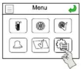
Access settings
Remember that the equipment is supplied configured and tested in factory. Only will be necessary to change the settings if you have reset the controller or if it has been replaced by another.
By accessing settings can be selected:
• Working mode of the fans.
- Settings used fan.
- Type of cold/hot coils thas has the unit.
- Enable the mixing module control and configure the type of control.
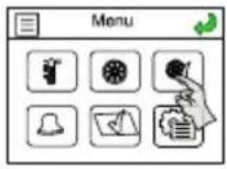

Code: 1111 OK


Constants air volume working mode (CAV)

Constants pressure working mode (COP)

Variable air flow
working mode (VAV)


Constant supply air temperature control

Room temperature control


Constant supply air temperature control with outdoor air compensation

AUTO: The controller determines automatically the best operation mode for each situation. It is based on the measured temperatures, and can be fixed as "Supply control with outdoor compensation" or "Room temperature control"


Without coils

heating coil

Cooling coil

Electrical heater

Cooling + Heating coil

Cooling coil + Electrical heater

Reversible water coil

Direct expansion coil


Without mixing module

The management of the dampers is done considering the concentration of CO2 mesured for an external CO2 sensor (accessory)

The management of the dampers is done just to achieve the setpoint temperature, without consider the air quality

The management of the dampers is done considering simultaneously the temperature setpoint and the CO2 concentration (accessory)
Advanced parameter setting
• Used to read the message of the alarm signalled on the main screen.
- Clock programming.

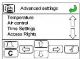
Navigation is done by the navigation arrows on the bottom of the display:

Displacement arrows

ENTER. Access to a parameter

ESC. Exit from the parameter

Confirm
Once in the advanced settings menu navigation is done by the arrows.
11.3. OPERATION FAN MODES
The Pro-Reg units can operate in 3 operating modes:
CAV: Operation at constant flow
VAV: Operation at variable flow
COP: operation at constant pressure
11.3.1. Constant airflow operation (CAV)
Mode recommended in installations where it is necessary to maintain a constant airflow.
The speed of the fans is defined to correspond to a precise airflow and to keep it constant.
The fan flow is controlled by a pressure transmitter integrated into the equipment in all versions.
The controller performs the conversion of the signal received from the pressure transmitter to flow, using the relation qv = k√ΔP . This parameter K depends on the fan construction and is different for each model.
In case CAV mode is selected, in the Main screen it is showed the actual m3/h of the fans with pressure transmitters and also a percentage of the maximum fan speed (Note that the unit has already been configured at the factory, so it is not necessary to make these adjustments except when replacing the controller or reset it):

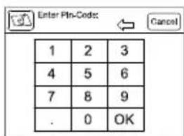
Code: 1111 OK


In order to obtain the actual flow, the parameter K has to be defined.
Factory settings
| Model K Factor Pressure | sensor | Pressure sensor (Airfl ow) | Slave fan factor | Number of fans | ||
| UTBS-2 | 62 | 2500 Pa 3000 Pa | 100% 1 | |||
| UTBS-3 | 75 | 2500 Pa 1000 Pa | 100% 2 | |||
| UTBS-5 | 100 | 2500 Pa 1000 Pa | 100% 2 | |||
| UTBS-8 | 116 | 2500 Pa 3000 Pa | 100% 2 | |||
Appearance main screen when the unit is configured in CAV mode.

CAV control mode selection
Access to the simplified parameter setting menu (via the password 1111) allows:
- The selection of Normal flow and Reduced flow of each fan.
• The night set point value of the fans.


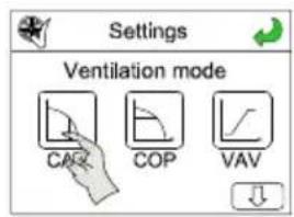

Code: 1111 OK
The choice between normal or reduced flow can be performed:
- manually
• automatically by programme schedule (see section Time programming) - remotely, by external digital contact (see section stop-start remote)
The switch over between the various set points will be done manually or automatically by a time programming.
A third set point, the “night speed”, may be entered via the control panel. The value in % corresponds to the percentage of the fan’s maximum capacity; it will be used during the night for free cooling (see corresponding function).
The selection of CAV mode in this installer menu automatically configures the screen of the user menu. The user can then change the unit's operation without modifying the settings.
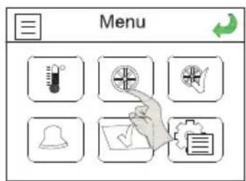
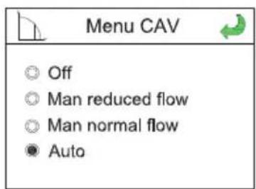
Off: stop the unit.
Manual Reduced flow, Manual Normal flow: set point manually selection.
Auto: selection of setpoint is done according to time programming.
Advanced level
To modify the proportional and integral bands, from the advanced parameters menu follow the following sequence:
1- Access to system level
![graph TD A["Manuel / Auto<br>Réglages<br>Configuration<br>Droils d'accès"] --> B["Entrer<br>Quitter<br>Changer mot de passe"] B --> C["Entrer<br>Mot de passe ****<br>Niveau actuel: Aucun"] D["Modifieur valeur<br>Code: 1111"] --> E["Entrer<br>Mot de passe 1111<br>Niveau actuel: Aucun"] E --> F["Entre…](/content/2026/05/987157/images/984758dabe10cfa5f863acbb443f9902d945bd7de64aea9e4edb679cc37fb475.jpg)
2- Adjust the CAV parameters
Advance
parameter


Manual/Auto
Settings
Configuration
Access Rights

Temperature control
Pressure control
Alarm settings

Pressure Ctrl. Supply
P.Band: 1000.0Pa
Acc-1: 20.0 s
Min.output: 20%
Change parameters

Factory setting data according to sizes
| Model Proportionnal band | Integral band |
| UTBS-2 5000 Pa 25s | |
| UTBS-3 5000 Pa 25s | |
| UTBS-5 5000 Pa 25s | |
| UTBS-8 5000 Pa 25s |
11.3.2. Variable airflow operation (VAV)
Mode recommended in single area configuration for variable airflow applications depending on a signal type 0-10v.
The set point value depends on a signal 0-10 V coming from an outdoor probe ( CO2 , temperature, relative humidity, etc.) or a manual percentage. The ratio between the fans is entered in the form of a discharge/supply percentage.
Functional parameter setting:
Access to the simplified parameter setting menu (via the password 1111) allows:
- The selection of the usage range of the signal 0-10V (see example below).
- The variation range of the supply fan's speed.
- The percentage applied to the discharge with respect to the supply.
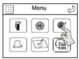

Code: 1111 OK


Usage example:
Connection of a CO2 probe of a measurement range 0-2000 ppm (0-10V). Speed minimum (25%) below 400 ppm and maximum (100%) over 1600 ppm
Vmin = 2 V (400ppm) Vmax = 8V (1600 ppm) Speed at Vmin = 25% Speed at Vmax = 100%

The selection of VAV mode in this installer menu automatically configures the screen of the user menu. The user can then change the unit's operation without touching the settings.


Off: Stop the unit.
Manual: Manually selection of fan's speed.
Auto: Automatic control according to external probe.
11.3.3. Constant pressure operation (COP)
Mode recommended in a multi-area configuration for variable airflow applications with several modulation systems of the airflows installed at the network level.
Airflows automatically modulated to maintain a constant pressure value measured by an outdoor pressure sensor.
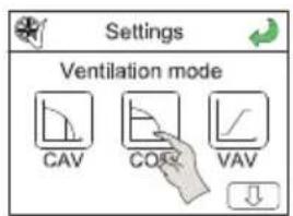
The access to the configuration menu of the COP mode is performed as follows:


Code: 1111 OK
Installation diagram pressure sensor
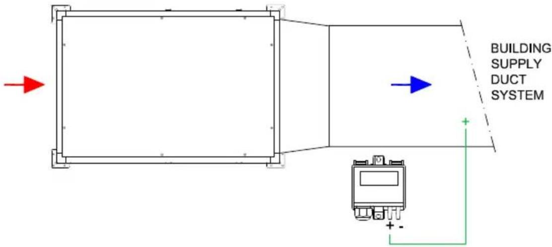
In case COP mode is selected, in the Main screen it is showed the actual Pa of the fans with pressure transmitters and also the speed of the fans (as a percentage of the maximum fan speed).

COP parameter settings mode
Access to the simplifi ed parameter setting menu (via the password 1111) allows:
- The selection of Normal flow and Reduced flow of each fan.
- The scaling factor in case one fan is slaved.
• The night set point value of the fans.

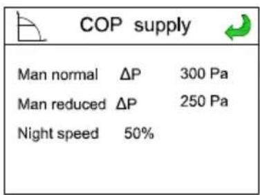
The choice between normal and reduced pressure can be performed:
- manually
• automatically with programme schedule (see section Time programming) - remotely, by external digital contact (see section force normal speed)
A third set point, the “night speed”, may be entered via the control panel. The value in % corresponds to the percentage of the fan’s maximum pressure; it will be used during the night for free cooling (see corresponding function).
The selection of COP mode in this installer menu automatically configures the screen of the user menu. The user can then change the unit's operation without modifying the settings.


Off: stop the unit.
Manual Reduced pressure / Manual Normal pressure: Setting manually selection. Auto: Selection of set point is done according to time programming (see Programme schedule section).
Advanced level
To modify the proportional and integral bands, from the advanced parameters menu follow the following sequence:
1- Access to system level

Factory setting data according to sizes
| Model Proportionnal band | Integral band |
| UTBS-2 5000 Pa 25s | |
| UTBS-3 5000 Pa 25s | |
| UTBS-5 5000 Pa 25s | |
| UTBS-8 5000 Pa 25s |
11.3.4. Control slave of an external fan (For all working modes)
The PRO-REG controller allows the control of an external fan as slave of the UTBS fan. These functionality is available for all the working modes (VAV, CAV o COP). The control can be done though an specific output 0-10V, terminals EAF / 0-10V in the electrical board (see electrical diagrams).
Slave fan adjustment is done from the Settings screen:


Code: 1111 OK

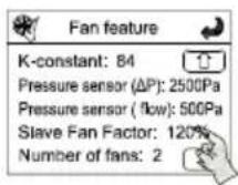

The setting corresponds to a percentage of the UTBS-PRO-REG fan current speed. Example:
| UTBS PRO-REG Fan speed Slave Factor (Settings) Terminal Output EAF | |
| 100% Vmax 100% 10V | |
| 70% 100% 7V | |
| 50% 100% 5V | |
| 100% Vmax 80% 8V | |
| 70% 80% 4.8V | |
| 50% 80% 4V | |
11.4. POSTHEATER CONTROL
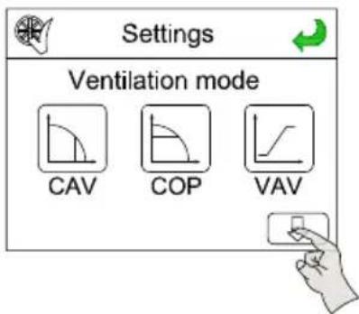
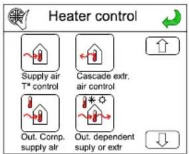
It is possible selecting between 4 different types of postheating control.
To select it follow the following sequence:


Code: 1111 OK

11.4.1. Constant supply air temperature maintenance

Heating mode
Constant supply air
T°C
Temperature controller works comparing supply air temperature with set point defined by console.
11.4.2. Constant ambient temperature maintenance

Heating mode
Room T°C control
Supply air temperature is controlled in cascade way with ambient temperature. Supply air temperature is defined depending on difference between ambient temperature and set point. In front of request, the controller tries to keep ambient temperature limiting duct temperature, which is maintained around 12 and 30°C, at same time.
11.4.3. Temperature set point adaptation vs. outdoor temperature
Heating mode
Constant supply air T°C with outdoor T°C compensation
Controller operation is similar to fi rst case. In this case, main difference is defi ning a compensation curve defi ned from factory with 8 set points instead of fi xing a single temperature set point.
Compensation curve
The supply set point is then adapted with respect to this curve. At any time, from the main screen you can manually change the supply temperature (range of +/-3°C).

11.4.4. Automatic control mode

Depending on the temperatures the controller select the most suitable temperature control mode, between "Supply temperature control with compensation for outdoor temperature" and "Room temperature control".
11.5. INITIAL TEMPERATURE SETPOINT
To set the setpoint temperature to maintain, keep the following sequence:


Code: 1111 OK

Introduce the desired temperaure
Once selected the setpoint temperature.

11.6. TIME PROGRAMMING
The controller has several clocks which allow the individual programming of: Normal Speed, Reduced Speed and Stop.
Speed selection is not available in VAV mode.
Normal speed: corresponding to normal pressure in COP mode and to normal flow in CAV mode
Reduced speed: corresponding to reduced pressure in COP mode and to reduced flow in CAV mode
Clock parameter setting:
The programmer works for intervals (outside these intervals the fans are stopped).
The installer can thus define two operation intervals in normal speed (only in CAV and COP modes).
It is possible defi ne the maximum of the two intervals per day and of speed.
For example:
The Normal Speed can be defined from 8:00 am to 12:00 pm in period 1
and from 2:00 pm to 6:00 pm in period 2
and the Reduced Speed from 6:00 am to 8:00 am in period 1
and from 12:00 pm to 9:00 pm in period 2
The programmable logic controller will then control the fans as follows:

To access to the programme schedule, select "Time settings" in the advance parameters.


![graph TD A["Advanced settings"] --> B["Time: 16:44\nDate: 2015-07-20\nWeekday: Monday"] B --> C["Defi ne the time periods when the unit will work at normal fan speed."] A --> D["Time/Date\nTimer Normal Speed\nTimer Reduced Speed\nExtended running"] D --> E["Defi ne the time periods when the unit wil…](/content/2026/05/987157/images/365912cb43c3a3f9a1c5bebefbedd8be7dc9b07237f46381452c320173633382.jpg)
Before modify the programming it is necessary to access as "Administrator level".
![graph TD A["Advanced settings"] --> B["Log on"] B --> C["Enter password"] C --> D["Actual level: None"] D --> E["C"] E --> F["Incrementar"] F --> G["Decrementar"] G --> H["Camblar digito"] H --> I["Salir"] I --> J["Advanced settings"] J --> K["Log on"] K --> L["Enter password 1111"] L --> M["Actual…](/content/2026/05/987157/images/e0747cc03291112168e2b4d1af16070a93c41da7c5a71e5f710299c978133d29.jpg)
In the time menu, before programming the intervals, make sure that the date and time are exact.
Time intervals parameter setting menu:
A “reduced speed prg” menu is also visible and is made up in the same way as the “normal speed prg” menu.
| Time settings | Time/date | Time: hh:mmDate: aaaa:mm:ddWeekday: ddddd | |
| Timer Normal Speed | Normal SpeedMondayPer 1: 00:00- 00:00Per 2: 00:00- 00:00 | Normal SpeedMonday->FridayPer 1: 00:00- 00:00Per 2: 00:00- 00:00 | |
| Normal SpeedTuesdayPer 1: 00:00- 00:00Per 2: 00:00- 00:00 | |||
| -- | |||
| Normal SpeedThursdayPer 1: 00:00- 00:00Per 2: 00:00- 00:00 | |||
| Normal SpeedFridayPer 1: 00:00- 00:00Per 2: 00:00- 00:00 | |||
| Normal SpeedSaturdayPer 1: 00:00- 00:00Per 2: 00:00- 00:00 | Normal SpeedSaturday->HolidayPer 1: 00:00- 00:00Per 2: 00:00- 00:00 | ||
| Normal SpeedSundayPer 1: 00:00- 00:00Per 2: 00:00- 00:00 | |||
| Normal SpeedHolidayPer 1: 00:00- 00:00Per 2: 00:00- 00:00 |
The intervals are programmed day by day or copied by selecting either the same programming from Monday to Friday and/or the same Saturday and Sunday and Holidays. Holiday periods are to be selected at the end of the table (24 possible periods).
| Time settings (following) | Holidays | Holidays (mm:dd)1: 01:01 - 01:012: 01:01 - 01:013: 01:01 - 01:01 |
| Holidays (mm:dd)4: 01:01 - 01:015: 01:01 - 01:016: 01:01 - 01:01 |
11.7. MIXING MODULE CONTROL (3 WAYS)
If it exists a mixing module instalated, it is necessary to specify the control type that it want to perform on it. It is possible to select between 3 control modes:
11.7.1. Without mixing module

Factory confi gurated by default, option for equipment installations 100% outside air or 100% indoor air.
11.7.2. CO 2 control

The management of the dampers depends on the quality of indoor air (it is necessary to install CO2 sensor). When the air quality is low (high level of CO2 ), the system gives priority to the entrance of outside air. As the CO2 level approaches to the introduced value as setpoint, it is closing the outside air damper, at the same time that opening the recirculated air.
11.7.3. Temperature control
The management of the dampers depends only on the existing thermal demand at all times and temperature of outside and return air.
The PRO-REG controller manages the opening/closing of the dampers to obtain maximum energy savings, without consider the air quality provided in the local. (Attention: With this operating mode exists risks to obtain a low quality indoor air.)
11.7.4. CO 2 control and temperature

The position of the dampers is done by simultaneous analysis of thermal demand and air quality (signal from the CO2 ). The controller tries to respond to the request of maintain the indoor air quality (ppm CO2 ) limiting at the same time the supply temperature.
11.8. CONTROL OF ISOLATION DAMPER
In the case of use the isolation damper, it is not necessary to perform an specific configuration nor enable the functionality in the unit. It is only necessary to install the dampers and wiring, as indicated in the MIXING DAMPER INSTALLATION section.
When you start the unit the damper will open. To stop the unit, it will stop.
By closing an external digital contact, it is possible to force the fan operation at normal speed for a setted time. (30 mins. by default)
The speed corresponds to the normal pressure setpoint set in COP mode or to the normal airflow specified in CAV mode.
The Boost function can be activated, only when the unit is not within a timer period of normal speed. In this case, even if boost is executed, the timer will start to count once the period of normal speed is finished (the boost order gets delayed).
This function is not available in VAV mode.

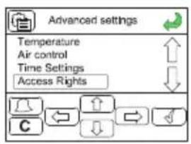


The activation of the Boost function has to be activated with an external switch. To activate, it is necessary to close the contact between +C and BT for 3" and then open it.

Once the Boost function has been activated, to cancel the forced normal speed period, it is necessary to do a Remote ON-OFF (see next point).
13. REMOTE STOP-START
It is possible to start-stop the unit by means of an external digital contact (see electric diagrams). The contact closure between +C and ES, will produce the unit stop.

When the equipment is stopped remotely the control hand terminal displays an alarm message. Although this is not a real anomaly, this way it is intended to warn about the possibility that the unit will be start up from remote at any time.
When Access to alarm menú it is shown the message "External Switch".
![graph LR A["2015-05-12 14:02"] --> B["Run mode: Off Consult alarms"] B --> C["21.4°C"] C --> D["800 m³/h 75%"] D --> E["Menu"] E --> F["External switch 23 Mar 11:32 Class: C"] F --> G["Advanced settings"]](/content/2026/05/987157/images/28d29a98831083424444a247a47a121a697bf1efdd0ed6f1c8fcd0018bb03ddd.jpg)
By default, this feature is disabled. To enable it is necessary to access from Advance Settings. This function is used during the summer to cool off buildings during the night by using fresh outdoor air. This allows reducing the need to resort to air conditioning during the day.
To use the free cooling by night function, the information received from the outdoor probe (fresh air) and from the discharge temperature probe is used. These two probes are present and integrated in the unit at the level of the taps.
The free cooling is only active if the start-up conditions are satisfied:
Start-up conditions:
• Less than 4 days have elapsed since the last start of the installation.
- The outdoor temperature during the previous operation period exceeded the force limit of 22°C[1] .
- It is between midnight 0:00 am [1] and 7:00 am [1] In the morning.
- The timer outputs for “normal speed”, “Extended running, Normal” and “External switch” are Off.
- A time program will be activated ("Start") within the next 24 h.
If ALL the conditions are satisfied, the free cooling starts running. It runs for 3 minutes to make sure that the temperature measurements are representative (by creating a movement of air in the ducts).
After three minutes, the controller checks the stop conditions:
Stop conditions:
- The outdoor temperature is above 18°C[1] or below 10°C[1] (risk of condensation).
- The discharge temperature is less than the stop value (18°C).
- The time programs (timer) for the normal speed, normal force run and the outdoor control are set to "Stop".
- It is later than 7:00 am [1] in the morning.
If at least one of these conditions is satisfied after the first three minutes of operation, then the unit is again stopped.
When the free cooling function is active, the fans run at maximum speed (it is possible to reduce this speed by setting the parameters); the coil and heat exchanger control outputs are switched off. The heating output remains inhibited for 60 (1) after the function is stopped.
(1) default values which can be changed by a parameter setting in "expert mode".
To activate the Free Cooling Night function it is necessary to access as administrator.
1- Access to system level
![graph TD A["Document"] --> B["Manuel / Auto\nRéglages\nConfiguration\nDroits d'accès"] B --> C["Entrer\nQuitter\nChanger mot de passe"] C --> D["Entrer\nMot de passe\nNiveau actuel: Aucun"] D --> E["Modifier valeur\nModifier la valeur\nCode: 1111"] E --> F["Entrer\nMot de passe\nNiveau actuel: Aucun…](/content/2026/05/987157/images/aa71fe18676e67c5f7374c5df88b1fd94fda62b7d4a4cfe02d1502c8e547fc59.jpg)
2- Activate the free cooling function and define the setpoint temperature
![graph TD A["Advance parameter"] --> B["Manual/Auto Settings\nConfiguration\nAccess Rights"] B --> C["In/out Settings sensor\nFunction control\nFan control"] C --> D["Refrigeración\nControl de bomba\nFree Cooling\nInicio aperte extra"] D --> E["Modify the value"] E --> F["Confirm the changes"] F -->…](/content/2026/05/987157/images/3dcab0b43bfb83136a03d810467892da5ffe77d969820aba3bd85d67e057aeca.jpg)
15. WATER HEATER FROST PROTECTION
In models with Water Heater, the temperature of the water return is continually supervised by a probe, in order to prevent it to freeze.
In case water temperature drops below 12° C, the water valve starts to open (if it already wasn't) and Frost Risk alarm is activated.
If water temperature falls below 7° C, then fans are stopped and the alarm Water temp too low, system off is activated. Till the temperature is not over 7° C, the unit will not turn on again.
Unit in OFF mode
When the unit is OFF, antifrost protection remains active trying to maintain a constant return water temperature of 25° C.
In some cases, after several adjustments or due to a bad working, it could be necessary to reset the controller. After isolating the unit and switching-off the main switch, open the door which gives access to the electronic board. Remove all the connectors attached to the controller with the exception of the 4-way electrical supply green plug connected to terminals 1,2, Earth and 4.

With a screwdriver, release the controller from the DIN rail on which it is mounted.
To reset the controller, it must be under voltage so re-energise the UTBS PRO-REG at the isolator and also on the unit by switching back on the main switch.
To reset the controller use a clip as shown in the picture: connect the ETD remote control cable and hook the Corrigo back onto the DIN rail. DO NOT CONNECT ANY OTHER PLUGS - AT THIS POINT, ONLY THE ETD REMOTE CONTROL AND 4-WAY ELECTRICAL SUPPLY PLUG SHOULD BE CONNECTED TO THE CORRIGO.

When the ETD cable and 4-Way electrical supply plug have been connected, perform the following sequence of operations:
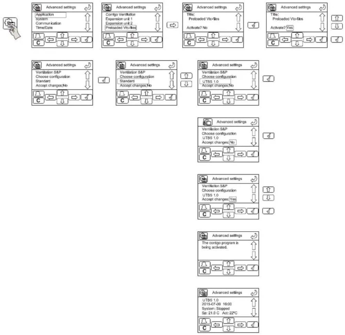
Isolate the electrical power supply again. Re-connect all of the other cables to the Corrigo controller and finally re-energise UTBS PRO-REG and the reset procedure is now complete.
The run mode of the system (I.e VAV/CAV/COP) should now be re-set-up, together with ensuring that the additional parameters (K-Constant, heater type etc.) are correct.
After reset the controller, it is necessary to reconfi gure the unit, as the factory set- tings are deleted.
Necessary reconfiguration:
- Language
- Cold and/or hot battery type
• Heating/cooling control - Initial temperature setpoint
- Fan operation mode
- K factor
K values corresponding to each model:
| Model K-factor Number of motors | |
| UTBS-2 62 1 | |
| UTBS-3 75 2 | |
| UTBS-5 100 2 | |
| UTBS-8 116 2 | |
- Pressure sensor:
Values of the set pressure range:
| Model Set pressure range |
| UTBS-2 0-3000 Pa |
| UTBS-3 0-1000 Pa |
| UTBS-5 0-1000 Pa |
| UTBS-8 0-3000 Pa |
- Mixing box control
- Advanced parameters
Advanced parameters must also be configured after the Reset:
- Time settings
- Night free-cooling
• Bacnet communication activation - Fire alarm strategy
17. CONNECTION TO BUILDING MANAGEMENT SYSTEMS (BMS)
17.1. RTU MODBUS
The controller in its standard version has an integrated RS485 communication port (to be used with an STP cable). The standard controller can communicate in Modbus via its RS485 port by simply activating an internal parameter “Advance Parameters”.
There is available a Communication manual where appear Modbus technical specifications and list of available registers.
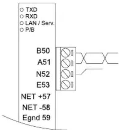
![graph TD A["Advance parameter"] --> B["Temperature\nAir control\nTime Settings\nAccess Rights"] B --> C["Log on\nLog off\nChange password"] C --> D["Log on\nEnter password ****\nActual level: None"] D --> E["Log on\nEnter password 1111\nActual level: None"] E --> F["Log on\nEnter password ****\nActu…](/content/2026/05/987157/images/d7b4329f05f23356228f444dc80c31221ceb00635d61113b570b6ad5abc854c6.jpg)
17.2. TCP/IP BACNET
PRO-REG controller is equipped with an integrated RJ45 port for TCP/IP communication, as support for BACnet IP communication. It's necessary to configure the IP address on each controller, and activate and address the BACnet IP using ETOOL software (E tool© is delivered as a self-installing program and can be downloaded from
http://www.regincontrols.com/Root/Documentations/42_105786/CorrigoEVentilation%203.4-1-24.zip)
It is necessary to indicate the names, IP fixed directions, sub-net masks and default gateway of each unit connected to the same network.

18. REPLACEMENT OF THE BATTERY FROM THE CORRIGO PROGRAMMABLE LOGIC CONTROLLER
When the “battery low” alarm appears and the red indicator light is lit, it means that the backup battery to save the memory and the real time clock is too low.
The procedure to change the battery is described below.
A capacitor allows backing up the memory and running the clock for approximately 10 minutes after the power is switched off.
If the battery can be changed in less than 10 minutes, the program does not have to be reloaded and the clock will continue to run normally.
The spare battery is type CR2032.
- Using a small screwdriver, pry up the clips on each side of the case to release the cover from the base.
- Hold the base and remove the cover.
- Grasp the battery and pull up gently until the battery exits from its holder.
- Replace the battery with a new.
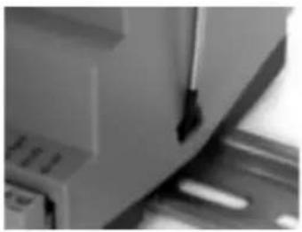
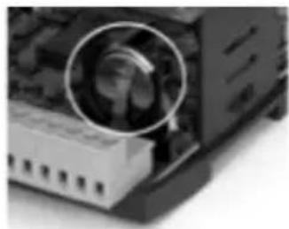
Warning: be sure to respect the polarity when inserting the battery.
| Anomaly Cause Solution | ||
| Diffi cult to start. Reduced power supply voltage. Insuffi cient static torque of motor. | Check motor specifi cation plate. Close the air inlets to reach the maximum speed. Change the motor is necessary. Contact the S&P Post-Sales service. | |
| Insuffi cient airfl ow. Insuffi cient pressure. | Blocked pipes and/or inlet points closed. Fan obstructed. Filter overloaded. Insuffi cient rotation speed. Sealed batteries. | Clean inlet tubes. Clean fan. Clean or replace fi lter. Check power supply voltage. Clean batteries. |
| Reduction in performance after a period of acceptable operation. | Leaks in the circuit before and/or after the fan. Damaged roller. | Check the circuit and restore original conditions. Check the impeller and if necessary, replace with an original spare part. Contact the S&P post sales service. |
| Supply air temperature too low. | Insertion of post-heating resistances. Contact the S&P post sales service. Reset by pushing the button RESET, all the thermal protectors of the resistance. | |
| Insuffi cient performance of water coil or direct expansion. | Fins dirty. Clean the exchanger. | |
| Formation of frost on the batteries. | Outside air below -5°C. | Insertion of pre-heating devices (anti-ice). Contact the S&P Customer Advice service. |
| Air pulsation. Fan working in flow conditions almost 0. Flow instability, obstruction or bad connection. | Modifi cation of the circuit and/or replacement of the fan. Clean and/or readjust the inlet channels. Operate the electronic regulator, increasing the minimum speed (insuffi cient voltage). Contact the S&P Customer Advice service. | |
| There is water inside the unit. | Drain clogged or wrongly dimentioned. | Check if exists a body/object obstructing the passage of water and remove it. Verify that the drain trap exists and is correctly sized according to the instructins of this manual. |
| Versions with water coils. Internal breakage of water coil. | Isolate the battery using the isolation valves. Repair the leak/ Replace the battery. | |
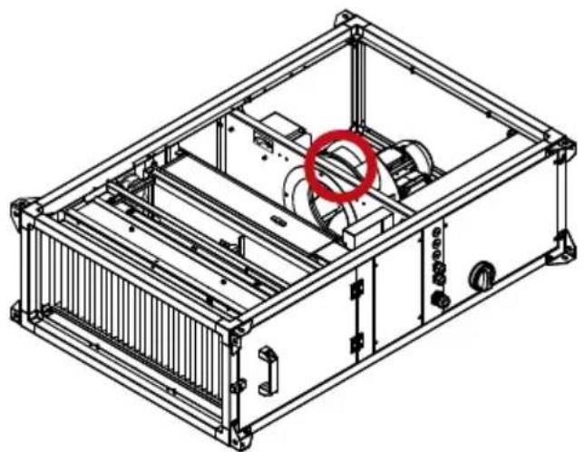
Fig.1. Location of the pulser for manual reset of thermal protectors

Danger of burns, there is a risk that the metal parts are at a high temperature.
19.2. FAILURE LIST
In case an alarm or a failure occurs, a "Maintenance To Do" message appears in red on the main screen. The alarm can then be consulted in the advanced menu. The error is then clearly identified on the screen. The list of error messages is given in the following subsection.
Alarms type A: they have to be acknowledged once the error has been solved to return to normal working.
Alarms type C: once the error has disappear they turns automatically off (not needed to acknowledge).
![graph TD A["2015-05-12 14:02"] --> B["21.4°C"] B --> C["Run mode: On Maintenance needed"] C --> D["Menu"] D --> E["Advanced settings"] E --> F["Filter guard 1\n23 Mar 11:32 Class: C"] F --> G["To move for the activated alarms"] G --> H["Block"] H --> I["ACKNOWLEDGE"] I --> J["Alarm reset (For A type…](/content/2026/05/987157/images/db44bc57682eeba265edff9cfb5d55ea93a3f654d6fd6d2f335ca14d8a33b4a3.jpg)
The following table shows the mode to proceed to detect and resolve any incidents shown:
| Alarm number | Alarm text Description Alarm | type | |
| 1 | Run Error Supply Air Fan Malfunction of supply air fan A | ||
| 6 | Change Filter Prefi lter % Filter need replacement C | ||
| 10 | Fire Alarm Fire alarm activated C | ||
| 11 | Remote off active Remote On/Off active A | ||
| 23 | Electric heating is overheated Electric Heater Thermal protectors activated C | ||
| 24 | Frost risk Frost protection function is overriding the control of the water heater output | C | |
| 25 | Water temp too low, system off Water temperature below frost limit value (<7°C) A | ||
| 27 | Sensor error outdoor temp | Malfunction of outdoor air temperature sensor | C |
| 41 | Manual heater control | The electric heater is in manual mode | C |
| 42 | Manual exchanger control | Heat exchanger output in manual control | C |
| 43 | Manual cooler control | Cooling output is in manual control | A |
| 48 | Internal battery error | Internal battery needs replacing | A |
| 49 | Sensor error Supply Air temp | Malfunction of supply air temperature sensor | A |
| 50 | Sensor error Extract Air temp Malfunction of extraction air temperature sensor A | ||
| 55 | Sensor error SAF pressure | Malfunction of supply air pressure sensor | A |
| 58 | Sensor error Frost Protection temp | Malfunction of water temperature sensor | C |
| 90 | Change External Filter | Extraction Air Filter needs replacement |
20. EMERGENCY OPERATIONS
- If any problems are noted on the unit, turn it off using the emergency shut-off device.
- These emergency operations will generally be the result of some problem with the electrical circuit, in which case you may have problems with the motors. You will therefore need to disconnect the power to locate the fault, which may be inside the unit (short circuit) or external to it (problems with the power supply, voltage variations, etc.).
- In the event of fire, it must be extinguished using suitable extinguishers. Extinguishers should be appropriate for use on electrical fires.
21. PREVENTIVE MAINTENANCE
- Preventive maintenance is a preset programme of checks that is followed regularly to prevent equipment breakdowns.
- The supplemental Building Facility Technical Regulations are applicable at all times to maintenance standards, except when justified otherwise for technical reasons.
- The maintenance supervisor should keep a copy of the preventive maintenance recommendations given below on file, making as many copies as needed for use.
-
According to the equipment's operating needs, it is crucial to make a list of those elements that are needed to quickly resolve equipment faults. This list will serve to determine the spare parts inventory needed to be able to perform repairs quickly.
-
A maintenance log should record each component serviced during maintenance, as well as activities performed or repairs made.
- Maintenance staff must have access to a specific training programme.
- Before starting maintenance operations on the unit, turn off the unit's main switch. Electrical shock can cause personal injury.
- Keep the following in mind when performing maintenance operations:
21.1. WATER COILS
- We recommend cleaning the coils once a year.
- Don't use abrasive cleaner.
- Brush off the fins that need it.
- Make sure that there is no leakage from pipework.
- If the coils are not used, please drain the water to avoid damage.
21.1.1 DX COILS
- We recommend cleaning the coils once a year.
- Don't use the abrasive cleaner.
- Make sure that there is the leakage from pipework.
21.2. DRAINAGE SYSTEM
- We recommend checking periodically the condensate drip tray and clean it.
- We recommend checking the siphon.
21.3. MOTORS
- Check the power consumption has not increased.
- Periodically check the electrical connections are making good contact; this will prevent breakdowns.
- We recommend checking the fan mounting periodically.
21.4. FANS
- Every three months, clean the dirt from the fan blades and bearings, since dirt can not only reduce airflow but also lead to unbalanced operation and increase noise.
- Periodically, test the airflow on each fan.
21.5. FILTERS
- To make sure that the filters are working properly, the pressure loss across the filter must be monitored precisely (since this is an indicator of dirt levels). The following table
indicates the maximum recommended values for pressure loss before filter replacement.
| Filter G4 M5 | M6F7F8F9 | |||||
| Pressure Loss (Pa) | 150 200 | 200 200 225 | 225 |
- Even if the maximum pressure loss has not been reached, filters should be inspected each month to make sure that the filter and filter housing are sealed.
- It is not recommended that filters be washed, since they will never recover their initial efficiency and doing so can produce wear on the filters. Although washing or vacuuming in the opposite direction from normal air circulation can achieve an optimal finish, it is recommended that you always have a set of replacement filters on hand. Under no circumstances should the unit be run without filters, since this can introduce dirt into vital components of the unit and lead to equipment wear and loss of efficiency.
Filter parts table
| Climate control model | Spare part code* Dimensions | (mm) | |||||
| G4 M5 | M6 F7 | F8 F9 | |||||
| UTBS-2 | 540 | 2055800 | 540 | 2056200 | 540 | 2056600 | 540 |
| UTBS-3 | 540 | 2055900 | 540 | 2056300 | 540 | 2056700 | 540 |
| UTBS-5 | 540 | 2056000 | 540 | 2056400 | 540 | 2056800 | 540 |
| UTBS-8 | 540 | 2056100 | 540 | 2056500 | 540 | 2056900 | 540 |
* Only valid for the main UTBS module.
In case of filters for heat recovery module contact your dealer to define the right references.
21.5.1. Filter replacement
The air conditioner is supplied with a filter mounted inside. Depending on the version it is possible to mount a second filter (order as accessory).
The way to access for maintenance depends on the unit type:
- Version UTBS-X P F7: Long frame version P F7, with capacity for mounting two filters: F7 factory mounted and possibility of mounting a second filter (supplied as an accessory).
- Version UTBS-X M5: Short frame version, equipped with a single M5 filter and without possibility to mount a second filter.
Loosen the fast taps in the filter access panel an retire the panel.

Remove the lateral metal support (a) and release the fil ters by the internal handle (b).
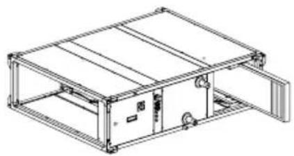
Retire the used filters.
Access by the bottom

- Loosen the fast taps in the filter bottom panel. Remove the lower panel of filter section.

- Remove the guide support that fi x the fi lters.

- Release the fi lters via the plastic handle (A) and retire the used fi lters.

- If the unit is equipped with a prefi liter, then it is necessary to remove the guide support that fix the prefi liter.

- Retire the used prefi lter.
SHORT FRAME VERSION M5:
Access by the side

Loosen the fast taps in the filter access panel an retire the panel.

Release the filters, sliding them through its guide.
Access by the bottom

Loosen the fast taps in the filter access panel an retire the panel.

Release the filter
21.6. COILS
If you detect any problem in the coils and they need to be removed, loosen the bolts from the panel where they are located, remove the panel and extract the coils. The coils are installed in slod for easy slide in and slide out.

21.7. DAMPERS
- Make sure that the damper can open and close unrestrictedly and the (way) is unobstructed.
- For manually controlled dampers fix the handle firmly to prevent the damper close while the unit is running.
21.8. SILENCERS
• To remove the baffles unscrew the corresponding side panel.

![graph TD subgraph Controlled Circuit A["UTBS-2/3/5 PRO-REG"] --> B["with electric heater"] B --> C["Electric Heater"] C --> D["Controlled Module"] D --> E["Power Supply"] end subgraph Transistors F["UTBS-2"] --> G["with 10 VDC"] G --> H["Controlled Module"] H --> I["Power Supply"] end subgraph Power…](/content/2026/05/987157/images/75abfe489bd64cb3df3adbf73c65d58deace2cf29e4a7ed001d03779507009f4.jpg)
![graph TD A["Controller"] --> B["PE 100k"] A --> C["PE 24Vdc"] A --> D["PE 30Vdc"] A --> E["PE 40Vdc"] A --> F["PE 50Vdc"] A --> G["PE 60Vdc"] A --> H["PE 70Vdc"] A --> I["PE 80Vdc"] A --> J["PE 90Vdc"] A --> K["PE 100Vdc"] A --> L["PE 110Vdc"] A --> M["PE 120Vdc"] A --> N["PE 130Vdc"] A --> O["PE 14…](/content/2026/05/987157/images/c8c06a59e3f2c553fba9485d1570cfd0ec8bbf68768cd672a7dac19d602063ce.jpg)

![graph TD subgraph_ControlPanel["Controller"] A["1 G 4 V"] --> B["200V P5"] C["3 G 7 V"] --> D["400V P6"] E["5 G 10 V"] --> F["600V P7"] G["6 G 15 V"] --> H["700V P8"] I["7 G 20 V"] --> J["800V P9"] K["8 G 25 V"] --> L["900V P10"] M["9 G 30 V"] --> N["1000V P11"] O["10 G 35 V"] --> P["1100V P12"] Q["…](/content/2026/05/987157/images/f3b690c7b4d6cf55463d4fe50ba68be01600834e19bb4c8e891ab4956297c92d.jpg)
Without mixing box UTBS-2/3/5 PRO-REG with electric heater
![graph TD A["UTBS-8 Pro-REG with electric heater"] --> B["Without mixing box"] B --> C["Controlled"] C --> D["Controller"] D --> E["Power Supply"] E --> F["Main Control Unit"] F --> G["Accessory"] G --> H["Top 100kW"] H --> I["Pressure (bpm)"] I --> J["Accessory"] J --> K["Main Control Unit"] K --> L…](/content/2026/05/987157/images/02ec86c434342db3000b10631c41874371d0e0c59d65362e59209a8613075899.jpg)

![graph TD subgraph Left_Supply A["UNIT SUPPLY 400V 3Ph+N 50Hz"] --> B["PE"] B --> C["SD"] C --> D["L1"] D --> E["L2"] E --> F["L3"] F --> G["N"] G --> H["PE"] H --> I["DC"] I --> J["PE"] J --> K["PE"] K --> L["PE"] L --> M["PE"] M --> N["PE"] N --> O["PE"] O --> P["PE"] P --> Q["PE"] Q --> R["PE"] R…](/content/2026/05/987157/images/266886b740ce0aceaecba003b795d1390b08b2607d0bd9d569acaa4f42045973.jpg)
![graph TD A["UTBS-8 Pro-REC with cooling cell + Electric Heater"] --> B["With mixing box"] B --> C["Controller"] C --> D["Sensor 1"] C --> E["Sensor 2"] C --> F["Sensor 3"] C --> G["Sensor 4"] C --> H["Sensor 5"] C --> I["Sensor 6"] C --> J["Sensor 7"] C --> K["Sensor 8"] C --> L["Sensor 9"] C --> M[…](/content/2026/05/987157/images/e5d39e3a1174e5bb536669b067cffdcd44a0164d887a5bc5bd2b07aff716aa24.jpg)
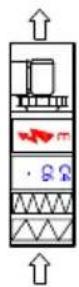
![graph TD A["UTBS-2/3/5 PRO-FEC"] --> B["Controller"] B --> C["Transistors"] C --> D["Power Supply"] D --> E["AC/DC02A and 60C2-A drive"] E --> F["AC/DC02A and 60C2-A drive"] F --> G["AC/DC02A and 60C2-A drive"] G --> H["AC/DC02A and 60C2-A drive"] H --> I["AC/DC02A and 60C2-A drive"] I --> J["AC/DC0…](/content/2026/05/987157/images/c5e62298beb0026ebb056a656574a4781d43207d3545cd7c7d0ce496fd52ff8f.jpg)
![graph TD subgraph Controller A["1 G"] --> B["2 GO"] C["3 G"] --> D["4 G"] E["5 G"] --> F["6 G"] G["7 G"] --> H["8 G"] I["9 G"] --> J["10 G"] K["11 G"] --> L["12 G"] M["13 G"] --> N["14 G"] O["15 G"] --> P["16 G"] Q["17 G"] --> R["18 G"] S["20 G"] --> T["21 G"] U["22 G"] --> V["23 G"] W["24 G"] --> X…](/content/2026/05/987157/images/099e3a673a012e3100aeda3d5113db2fa0ee89361c806b481b14811d72870a65.jpg)
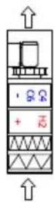
UTBS-2/3/5 PRO-REG with cooling coil + Heating coil
With mixing box
![graph TD subgraph ControlLEER A["Controller"] --> B["Switch"] B --> C["Exhaust Air Fan (Save Fan)"] B --> D["Control Module 1"] B --> E["Control Module 2"] end subgraph Power Supply F["Power Supply (Flow)"] --> G["Control Module"] H["Power Supply (Cap) --> I[Control Module"] J["Power Supply (Cap) --…](/content/2026/05/987157/images/5171e0e9da2a2d049233dae1b2c798d48b858401b9d46c54f38e40edc918dc9b.jpg)

UTBS-8 PRO-REG with cooling coil + Heating coil
With mixing box
![graph TD subgraph Controlled A["Controller"] --> B["UTBS-2"] B --> C["Transistors"] C --> D["Sensor 1"] C --> E["Sensor 2"] C --> F["Sensor 3"] C --> G["Sensor 4"] C --> H["Sensor 5"] C --> I["Sensor 6"] C --> J["Sensor 7"] C --> K["Sensor 8"] C --> L["Sensor 9"] C --> M["Sensor 10"] C --> N["Sensor…](/content/2026/05/987157/images/2d58cec0285c1514c56bbda9f03d7df6a4b76c9c654a73b3908a44c264ce7711.jpg)

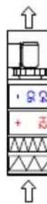
![graph TD A["Controller"] --> B["Safety Sensor 1"] A --> C["Safety Sensor 2"] A --> D["Safety Sensor 3"] A --> E["Safety Sensor 4"] A --> F["Safety Sensor 5"] A --> G["Safety Sensor 6"] A --> H["Safety Sensor 7"] A --> I["Safety Sensor 8"] A --> J["Safety Sensor 9"] A --> K["Safety Sensor 10"] A -->…](/content/2026/05/987157/images/8aa9020f36eb473c474f333971c8d189a94e7a9222c0441c9e441f1099d6f394.jpg)

UTBS-8 PRO-REG with cooling coil + Heating coil
Without mixing box
![graph TD subgraph ControlRoom A["Controller"] --> B["UTBS-3 / UTBS-5"] B --> C["UTBS-2"] C --> D["USB"] D --> E["RS"] E --> F["Control Unit"] end subgraph ControlRoom G["RS"] --> H["Switch Generation"] I["Control Unit"] --> J["Switch Generation"] K["Control Unit"] --> L["Switch Generation"] end subg…](/content/2026/05/987157/images/f22356ac3447659bab009de723fec7e7d0ca98313a970ee4b1daf6e10ef238e7.jpg)
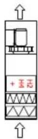
UTBS-2/3/5 PRO-REG with heating coil
With mixing box
![graph TD subgraph ControlCircuit A["SAF 1"] -->|10 VDC| B["SAF 2"] A -->|10 VDC| C["SAF 3"] D["SAF 4"] -->|10 VDC| E["SAF 5"] D -->|10 VDC| F["SAF 6"] G["SAF 7"] -->|10 VDC| H["SAF 8"] G -->|10 VDC| I["SAF 9"] J["SAF 10"] -->|10 VDC| K["SAF 11"] J -->|10 VDC| L["SAF 12"] M["SAF 13"] -->|10 VDC| N["S…](/content/2026/05/987157/images/6251b9ea18c5dc5e994869d0b1cf844794f80ba0d616621ceb7a399542a4a075.jpg)

UTBS-8 PRO-REG with heating coil
With mixing box
![graph TD subgraph Controlled A["Controller"] --> B["UTBS-2"] B --> C["Transistors"] C --> D["Safety Switch"] D --> E["Power Supply"] end subgraph Power Supply F["ACCESSION"] --> G["ACCESSION"] H["POWER Supply"] --> I["POWER Supply"] end J["Controlled"] --> K["UTBS-2"] K --> L["Transistors"] L --> M[…](/content/2026/05/987157/images/998c309e6cdc5808615260d77e8f03f16cb61fd3b3638798c9d3eab0c9a5a6d5.jpg)

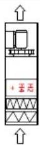
UTBS-8 PRO-REG with heating coil
Without mixing box
![graph TD subgraph UTBS-2/3/5 PRO-REG direction TB A["UNIT SUPPLY"] --> B["PE"] B --> C["ACCESSIONARY"] C --> D["SO Box"] D --> E["ACCESSIONARY"] E --> F["REB-ECOWATT"] F --> G["ACCESSIONARY"] end subgraph UTBS-3/UTBS-5 H["CONTROLLER"] --> I["4 wires shielded cable (10 m. cable inductor)"] I --> J["S…](/content/2026/05/987157/images/e9c835e8c8524a8457ca2c810bf407f26a060a86497b6d78c768737de88c867e.jpg)

UTBS-8 PRO-REG with cooling coil (reversible)
With mixing box
![graph TD subgraph "Without mixing box" A["UNIT SUPPLY 230V 1PH+N 50Hz"] --> B["PE"] B --> C["PD"] C --> D["Controller"] D --> E["4 Vize iminled cable (10 m, cable included)"] E --> F["External Filter PS (Accessory)"] E --> G["Digital Input (Free of voltage)"] E --> H["Digital Input (Free of voltage)…](/content/2026/05/987157/images/60efec4a5ed9384318f0af6204ec7a4ebf2ddc4ef1acc787316a6d63ba9f8d1a.jpg)

![graph TD A["UNIT SUPPLY 400V 3Ph+N 50Hz"] --> B["L1 L2 L3 N PE"] B --> C["L1 L2 L3 N PE"] C --> D["SO L1 08"] D --> E["+C 20 24Vac"] E --> F["CONTROLLER"] F --> G["P1 RxTx TCP/HP P/B"] G --> H["EXT. DISPLAY"] H --> I["PreTiter&Fiber PS"] I --> J["External Fiber PS (Accessory)"] J --> K["Boost"] K --…](/content/2026/05/987157/images/d3bcda661baa00f17a8c7df2a118ffada4feb0fe34a1b23140f00ca44988b7c9.jpg)
![graph TD subgraph Control in Slave Mode: Master direction TB A["UTBS-2/3/5 PRO-REG"] --> B["Controller"] B --> C["PTC"] B --> D["AC"] B --> E["AC"] B --> F["AC"] B --> G["AC"] B --> H["AC"] B --> I["AC"] B --> J["AC"] B --> K["AC"] B --> L["AC"] B --> M["AC"] B --> N["AC"] B --> O["AC"] B --> P["AC"…](/content/2026/05/987157/images/57bb55630e92b09d9187b02ebc567b9ad55e8775006831f1b296833b7b295041.jpg)
![graph TD subgraph Controlled A["Controller"] --> B["Switch"] B --> C["External Fan (Save Fan)"] C --> D["Supply Fan"] D --> E["RS-SCOMAT1"] E --> F["Output Unit"] F --> G["SO2-GO 40V"] G --> H["CAN/AN"] H --> I["Power Supply"] I --> J["Output"] end subgraph External K["External Power Supply"] L["Ext…](/content/2026/05/987157/images/b3f4e86bd7b836df5db7f36085d833cc41a499725691f30658e9b720efda3ccc.jpg)
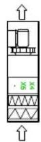
UTBS-8 PRO-REG with Direct Expansion coil (versible) Control in slave mode. Master control by DX-Kt
With mixing box
![graph TD subgraph Control A["UTBS-2/3/5 PRO-REG with Direct Expansion coil (reversible)"] B["Control in slave mode. Master control by DX-Kit"] C["Without mixing box"] end subgraph Sensor1 D["CONTROLLER"] E["UTBS-2"] F["UTBS-3 / UTBS-5"] end subgraph ControlPanel G["UTBS-2"] H["UTBS-3 / UTBS-5"] end…](/content/2026/05/987157/images/2852b0c479d80f23237a387d05739feaed0b6d61b55b392fc042638feca9b66d.jpg)
![graph TD A["Controller"] --> B["External RF fan (Slave Fan)"] A --> C["SAF"] A --> D["SAF"] A --> E["SAF"] A --> F["SAF"] A --> G["SAF"] A --> H["SAF"] A --> I["SAF"] A --> J["SAF"] A --> K["SAF"] A --> L["SAF"] A --> M["SAF"] A --> N["SAF"] A --> O["SAF"] A --> P["SAF"] A --> Q["SAF"] A --> R["SAF"…](/content/2026/05/987157/images/5d2c3aa4d6eecf0ab6eec84f5cc43ec2a880ccd82e6f171b1deb113ac9dff443.jpg)

UTBS-8 PRO-REG with Direct Expansion coil (versible) Control in slave mode. Master control by DX-Kt
Without mixing box

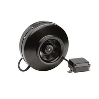
- INDEX
- OVERVIEW
- SAFETY STANDARDS AND "EC" MARKING
- GENERAL STANDARDS
- WARNING: CONTROLS DISCONNECTED FOR MAINTENANCE
- UNIT LABELING
- TECHNICAL CHARACTERISTICS
- VENTILATION SECTION
- COIL SECTION
- WATER COILS
- ELECTRIC HEATERS
- DIRECT EXPANSION COIL (DX)
- 4 ROWS COIL
- 6 ROWS COIL
- FILTERED SECTION
- HANDLING
- INSTALLATION
- IDENTIFICATION UNIT PARTS
- INSTALLATION SITE
- MAINTENANCE SPACE
- DIMENSIONS
- SHORT VERSION: SINGLE FI LTER TYPE M5
- LONG VERSION: F7 FILTER WITH ADDITIONAL FILTER MOUNTING CAPACITY
- SHORT VERSION: SINGLE FILTER TYPE M5
- SPACE FOR MAINTENANCE
- L VERSIONS
- R VERSIONS
- ASSEMBLING THE MODULES
- MOVE THE FL ANGE FROM THE MAIN MODULE TO THE ACCESSORY MODULE
- ADDITIONAL FILTERS MOUNTING
- ASSEMBLING FL EXIBLE CONNECTIONS
- MIXING MODULE INSTALLATION
- INSTALLATION WITH ISOLATION DAMPER
- CONNECTING THE UNIT TO THE WATER NETWORK
- CONNECTING THE UNIT TO THE DUCT SYSTEM
- VERY IMPORTANT
- DIRECT EXPANSION COILS CONNECTION (DX)
- COIL CHARACTERISTICS
- DX 4 ROWS COIL
- DX 6 ROWS COIL
- INSTALLATION RECOMMENDATIONS
- DRAINAGE SYSTEM
- ELECTRICAL CONNECTION
- TEMPERATURE PROBES LOCATION
- START-UP PROCEDURE
- IMPORTANT: BEFORE ACCESS THE UNIT, IT IS OBLIGATORY TO SWITCH OFF THE ELECTRICAL SUPPLY BY MEANS OF THE GENERAL SWITCH PLACED IN THE CABINET BOX
- CHANGE LANGUAGE
- SIMPLIFIED MENUS / ACCESSES
- USER LEVEL
- OPERATING MODE SELECTION
- INSTALLER LEVEL
- ALARM DISPLAY
- SCREEN DISPLAY SETTINGS
- ACCESS SETTINGS
- ADVANCED PARAMETER SETTING
- OPERATION FAN MODES
- CONSTANT AIRFLOW OPERATION (CAV)
- CAV CONTROL MODE SELECTION
- ADVANCED LEVEL
- ACCESS TO SYSTEM LEVEL
- ADJUST THE CAV PARAMETERS
- FACTORY SETTING DATA ACCORDING TO SIZES
- VARIABLE AIRFLOW OPERATION (VAV)
- FUNCTIONAL PARAMETER SETTING
- USAGE EXAMPLE
- CONSTANT PRESSURE OPERATION (COP)
- INSTALLATION DIAGRAM PRESSURE SENSOR
- COP PARAMETER SETTINGS MODE
- CONTROL SLAVE OF AN EXTERNAL FAN (FOR ALL WORKING MODES)
- POSTHEATER CONTROL
- CONSTANT SUPPLY AIR TEMPERATURE MAINTENANCE
- CONSTANT AMBIENT TEMPERATURE MAINTENANCE
- TEMPERATURE SET POINT ADAPTATION VS. OUTDOOR TEMPERATURE
- COMPENSATION CURVE
- AUTOMATIC CONTROL MODE
- INITIAL TEMPERATURE SETPOINT
- TIME PROGRAMMING
- CLOCK PARAMETER SETTING
- FOR EXAMPLE
- TIME INTERVALS PARAMETER SETTING MENU
- MIXING MODULE CONTROL (3 WAYS)
- WITHOUT MIXING MODULE
- CO 2 CONTROL
- TEMPERATURE CONTROL
- CO 2 CONTROL AND TEMPERATURE
- CONTROL OF ISOLATION DAMPER
- REMOTE STOP-START
- START-UP CONDITIONS
- STOP CONDITIONS
- ACTIVATE THE FREE COOLING FUNCTION AND DEFINE THE SETPOINT TEMPERATURE
- WATER HEATER FROST PROTECTION
- UNIT IN OFF MODE
- CONNECTION TO BUILDING MANAGEMENT SYSTEMS (BMS)
- RTU MODBUS
- TCP/IP BACNET
- REPLACEMENT OF THE BATTERY FROM THE CORRIGO PROGRAMMABLE LOGIC CONTROLLER
- FAILURE LIST
- EMERGENCY OPERATIONS
- PREVENTIVE MAINTENANCE
- 21.1.1 DX COILS
- MOTORS
- FANS
- FILTERS
- FILTER REPLACEMENT
- ACCESS BY THE BOTTOM
- SHORT FRAME VERSION M5
- ACCESS BY THE SIDE
- COILS
- DAMPERS
- SILENCERS
Brand : Soler & Palau
Model : UTBS PRO-REG ECOWATT
Category : Ventilation