ORKA HR D150 - Ventilation Soler & Palau - Free user manual and instructions
Find the device manual for free ORKA HR D150 Soler & Palau in PDF.


| Product Type | Mechanical Ventilation Unit with Heat Recovery |
| Model | ORKA HR D150 |
| Brand | Soler & Palau |
| Duct Diameter | 150 mm |
| Height | 320 mm |
| Width | 320 mm |
| Depth | 650 mm |
| Weight | 8.5 kg |
| Power Supply | 230 V / 50 Hz |
| Max Airflow | 150 m³/h |
| Heat Recovery Efficiency | >85% |
| Filter Type | ISO Coarse 60% (G4) or ISO ePM1 50% (F7) |
| Control | Manual speed switch (3 speeds) or optional remote control |
| Noise Level (max) | 42 dB(A) at 3m |
| Installation | Wall-mounted or suspended with brackets |
| Safety | IPX4 protection, thermal cut-out |
| Maintenance | Clean filters every 6 months; replace every year |
| Spare Parts | Filters, motors, control boards available from authorized dealers |
| Warranty | 2 years |
Frequently Asked Questions - ORKA HR D150 Soler & Palau
User questions about ORKA HR D150 Soler & Palau
0 question about this device. Answer the ones you know or ask your own.
Ask a new question about this device
Download the instructions for your Ventilation in PDF format for free! Find your manual ORKA HR D150 - Soler & Palau and take your electronic device back in hand. On this page are published all the documents necessary for the use of your device. ORKA HR D150 by Soler & Palau.
USER MANUAL ORKA HR D150 Soler & Palau
This appliance can be used by children aged from 8 years and above and persons with reduced physical, sensory or mental capabilities or lack of experience and knowledge if they have been given supervision or instruction concerning use of the appliance in a safe way and understand the hazards involved. Children shall not play with the appliance. Cleaning and user maintenance shall not be made by children without supervision.
CONTENTS
- General information
- Technical information
- Installation
- Characteristics and electrical connections
- Control of ORKA
- Commissioning the ORKA
- Maintenance
- Putting out of service and recycling
- ECODESIGN Technical sheet
The following items are included:
- 1 x ORKA ST
- 1 x remote control
- 1 x condensate drain tube + support
- 3 x inclination feet
- 3 x reductions ∅ 125/160
- 4 x plug ∅80mm
- 1 x instruction manual
1. GENERAL INFORMATION
1.1. INTRODUCTION
This manual is intended for the use of the central balanced-flow high efficiency ORKA ST and its peripherals (ductwork, vents, controllers).
It is designed to provide clear and safe guidance for the design, installation and use of the product.
The products are constantly evolving and so, Soler & Palau reserves the right to modify this manual without prior notice.
1.2. WARRANTY AND LIABILITY
Warranty
The ORKA ST heat recovery system has two years warranty from the date of purchase. This warranty includes free delivery of necessary spare parts.
The warranty does not cover:
• Installation and removal costs.
- Defects that, in the opinion of Soler & Palau, are due to improper installation, handling, neglect or accidental damage.
- Those defects that arise as a result from operations or repair performed by a third party without permission from Soler & Palau.
- To return a defective part, the user should contact their installer.
Liability
ORKA ST is designed for ventilation systems in individual dwellings. Soler & Palau is not responsible for damage caused by:
- Improper use.
• Normal wear of components. - Failure to follow the instructions in this manual concerning safety, use and installation.
• The use of parts not supplied by Soler & Palau.
1.3. SAFETY
General health and safety standards
The heat exchanger ORKA ST has been designed to be incorporated into a ventilation system. Following installation, there should be no risk to safety, health and the environment according to EC directives. This also applies to other products used in the installation.
The following general guidelines are important:
- Follow the safety instructions to prevent injuries and damage to the motorised fans.
- The technical characteristics described in this manual may not be changed.
- The motorised fans must not be modified.
- The motorised fans must be supplied with a single phase AC supply of 230 V / 50 Hz.
- So that the installation complies with EC directives, the ORKA HR must be connected to the electricity grid according to current national standards.
- The device must be installed so that under normal operating conditions, there is no risk of contact with moving parts and power.
- The ORKA ST meets legal requirements for electrical equipment.
- Before working on the machine, always turn the power off.
- Use appropriate tools.
- Use the machine only for the purpose for which it is intended.
2. TECHNICAL INFORMATION
2.1. INTRODUCTION
ORKA ST ensures optimal ventilation of the house with maximum energy recovery. Stale air is extracted from the "wet" rooms (bathrooms, toilets, laundry rooms, etc.) and fresh air is supplied into the main "habitable" rooms (living room, bedrooms, studys,...). Both airflows are filtered before forwarding to the heat recovery unit, where warmth from the stale, outgoing air is transferred to the cooler incoming airflow. The unit performance can reach:
- HR: 92%
• ST:70%
By avoiding the heat exchanger, the by-pass system 100% of the ORKA product allows you to enter fresh night air without letting it warm up from contact with the hot air accumulated during the day. This system works manually (See chapter 5.2).
2.2. DESCRIPTION
• HR and ST: Extraction: 4 spigots d.80 +spigot d.125.
- HR D150 and STD150: extraction: 1 spigot d.150 and 1 spigot d.125.
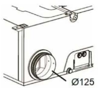
- The rest of connections: 3 x d.125 (adapter 125/150-160 supplied for each spigot).
![graph TD A["Extraction of bathroom and kitchen"] --> B["Covers to fi liters access"] B --> C[" Fresh air from outside"] D["Supply to living room and bedrooms"] --> E["Discharge to outside"] F["House"] --> G["Greenhouse"] style A fill:#f9f,stroke:#333 style B fill:#ccf,stroke:#333 style C fill:#cfc,s…](/content/2026/05/979701/images/1badfafd34d1ec4ad52333af1eec7b16f166164b892e3c408f28eba95fd6679a.jpg)

New fresh air inlet:
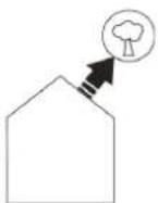
This spigot is to connect the supply duct of fresh air from outside. Install the fresh air intake (wall or roof) a sufficient distance from any area of high pollution (trees, exhaust fumes, road, etc).
This duct must be sealed and insulated to prevent condensation on the outside and inside.


Supply fresh air into the building:
Connected to the air intake duct in the property.
To avoid thermal losses, it is recommended to use insulated ducts for the warmed air.

Extract air from the building:
Connected to the extract duct from the property.
To avoid thermal losses and optimise the performance of the installation, it is recommended to use insulated ducts for the warm air.
Extract air from the building:
Connected to the extract duct from the property.
To avoid thermal losses and optimise the performance of the installation, it is recommended to use insulated ducts for the warm air.
This duct must be well sealed and thermally insulated to avoid condensation both on the inside and outside.


By pass:
The 100% by-pass system of the ORKA allows the introduction of cooler fresh air (during the evenings and in the night) avoiding the heat exchanger and thus without it being tempered by the outgoing warm air which has accumulated in the house during the day.

Alarm fi lter change:
The unit has a timer "12 months TIMER" that alerts the user when to change the filters.
2.3. DIMENSIONAL CHARACTERISTICS
2.3a. Central

Weight: 20 kg
2.3b. Remote control

3. INSTALLATION

The equipment ORKA must be installed in a heated room in the home ( >10°C ) if this is not possible, the condensate outlet must be thermally isolated.

In areas that regularly have negative temperatures ( <-2°C ) a pre-heating battery must be installed. Operating temperature ( <-2°C , 45°C ).

Ducts must be thermally insulated and correctly installed.

Uninsulated duct

Insulated duct

Insulated duct
Spigot arrangement ∅ 80 mm
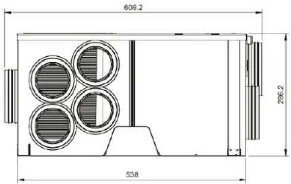
Spigots that are not used must be plugged with the supplied accessory.

3.A. MOUNTING IN A FALSE CEILING
To ensure correct installation, it is necessary to place the supplied positioning accessories as indicated:
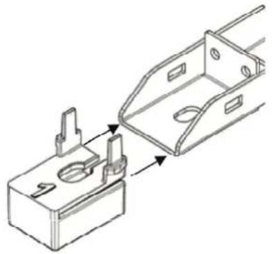
Extraction: without accessories

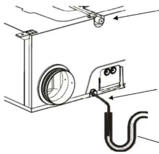
The condensate outlet that is not used must be plugged with the supplied plug.
The condensate tube must maintain the slope throughout its length. Fix the duct if it is necessary.
Installation should have a siphon filled with water as indicated:
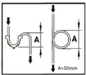
For correct maintenance, a sufficiently large equipment access hatch must be installed.
Recommended Dimensions: 1000 x 750 mm.
3.B. MOUNTING IN A FLOOR
To ensure correct installation, it is necessary to place the supplied positioning accessories as indicated:

Discharge side: without accessory
The condensate outlet that is not used must be plugged with the supplied plug.
The condensate tube must maintain the slope throughout its length. Fix the duct if it is necessary.
Installation should have a siphon filled with water, as indicated:
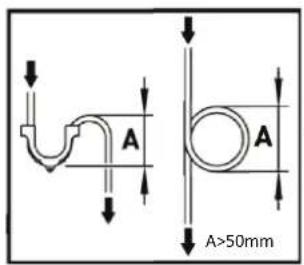

For correct maintenance, access must be allowed to the equipment to each exposed side. Access is from the top.
SAMPLE "MIXED DISTRIBUTION" ASSEMBLY
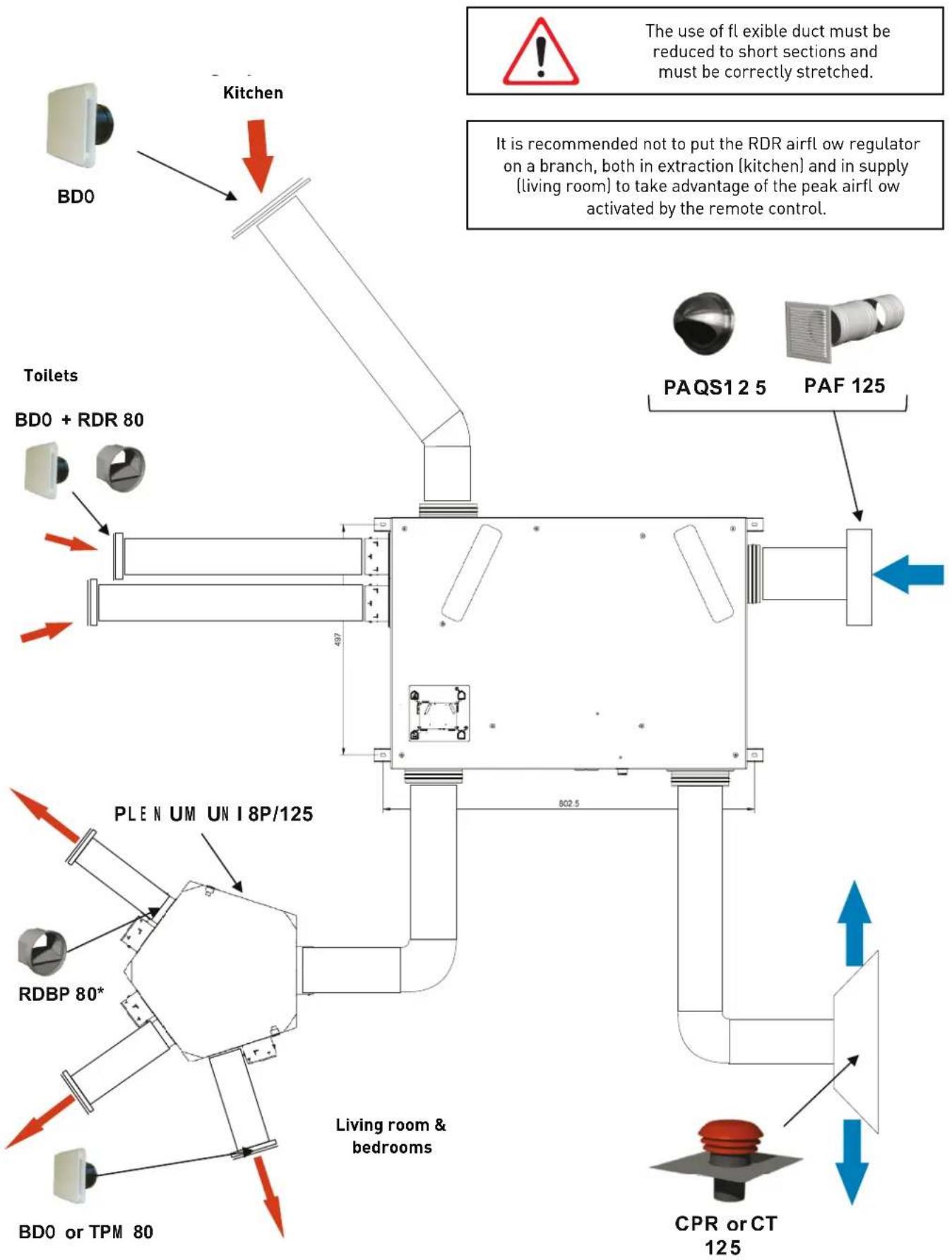
SAMPLE "PLENUM DISTRIBUTION" ASSEMBLY
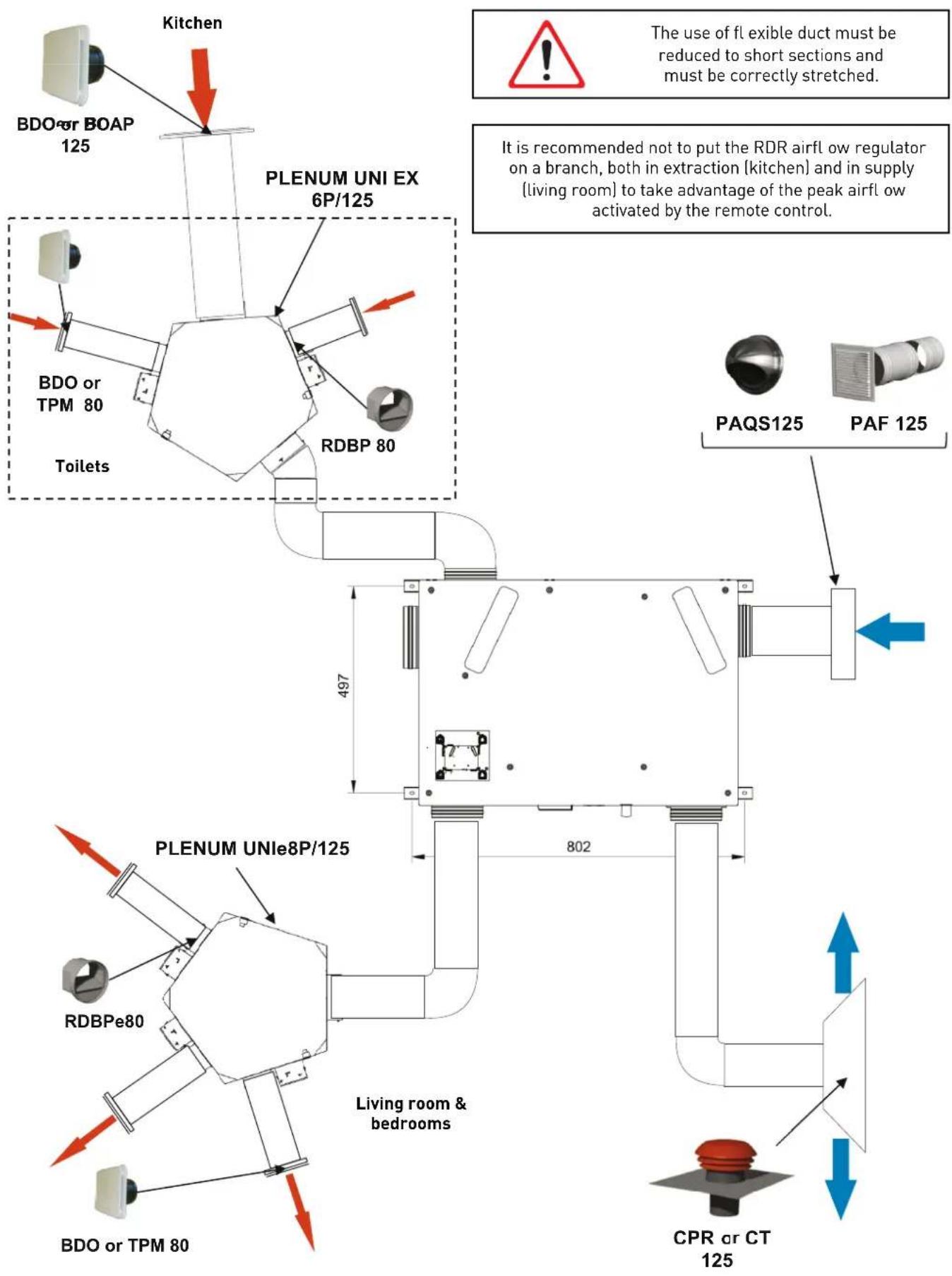
SAMPLE "DISTRIBUTION" ASSEMBLY

The use of fl exible duct must be reduced to short sections and must be correctly stretched.
![graph TD A["Toilets"] --> B["BDOó+ RDR 80"] C["Kitchen"] --> D["BDOó+ RDR 125"] E["PAQS125"] --> F["PAF 125"] G["BDOó+ RDR 80"] --> H["BDOó+ RDR 80"] I["CPR or CT 125"] --> J["Living room & bedrooms"] K["497"] --> L["802"] M["It is recommended not to put the RDR airfl ow regulator on a branch, both…](/content/2026/05/979701/images/d6df993d210fb04ece4c89a0330fb92ee13f3afd9d9e8b713ca73b6cf9be97ce.jpg)
4. CHARACTERISTICS AND ELECTRICAL CONNECTION
Power: Single phase 230V-50Hz
Max. current: 0,7 A
Electrical protection: 2 A (curve C)
Max.Power: 145 W
Maximum ambient temperature: 50°C
Maximum flow temperature: 45°C
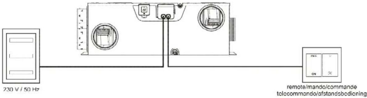
Conf i guration A:
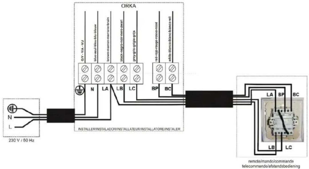
Configuration B:

5. CONTROL OF ORKA
5.1. INSTALLATION
5.1a. Airflow selection
The equipment has 2 configurations (A and B) for low speed depending on the connection (see chapter 4). The peak airflow (high speed) function is common to both configurations.
![| q_v [m³/h] | P_af [Pa] | P_abs [W] | | ---------- | --------- | --------- | | 0 | 350 | 60 | | 50 | 300 | 70 | | 100 | 250 | 80 | | 150 | 200 | 90 | | 200 | 150 | 100 | | 250 | 100 | 130 |](/content/2026/05/979701/images/6b76b5732a41b41679c8dd749ef5a4eddc4638f91b38df3d7e9fbe5a2237a3a4.jpg)
5.1b. Alarm change filters
The unit has a timer "12 months TIMER S&P" that alerts the user when to change the filters. It is a movable device and must be located where the user can view the alarm status.

The alarm is timed to activate at 12 months. Once this time has elapsed, the pilot will light up every 10 seconds during the first 4 days. Subsequently, the flashing will be every 30 seconds for the next 9 days.
When the filters have been changed, the alarm must be reactivated by pressing the button for 5 seconds.
To check the remaining time until the end of the timing, press the button for 2/3 seconds and the pilot light will illuminate a number of times to the number of months remaining to reach 12 months.
To confirm that the battery has sufficient charge, press the button (<1 second) and the pilot light will illuminate once.
If not, the battery should be replaced with a new one. The remaining time for the alarm activation is saved.
The battery life for normal use is approximately 3 years.
The battery is CR2032 type.
Remove the battery protection for activation.
5.2. DURING USE
The remote control allows the user to:
- Activate the peak airflow
- Activate the by-pass 100%


Low airflow:
Activates the low airflow corresponding to curve A or B depending on the configuration chosen in the electrical connection.

Peak airfl ow:
Peak airflow activation.

By-pass (ON/OFF):
By avoiding the exchanger, the 100% ORKA bypass system allows fresh air from outside to be introduced without being overheated by the outgoing air from indoors, this is mainly recommended in summer to get free cooling. Manual activation.
6. COMMISSIONING THE ORKA
To start your ORKA unit use the following process:
-
Verify that all system components are correctly installed and connected:
-
Fresh air intake duct insulated and connected correctly (Do not use a fresh air intake equipped with insect screen).
- Fresh air and exhaust ducts insulated and connected correctly.
- Fresh air and exhaust vents connected.
- Flow regulators mounted in the right direction (if installed).


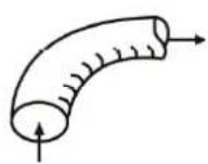
• Air outlet using insulated duct and connected to the outside (Using a roof cowl or outlet without an insect screen).
- Insulated fl exible ducts taut and large radius bends (if installed).
- Check that the unused spigots on plenums are sealed (if installed).
• Condensation drain well connected (siphon).
- Check that all connections are sealed (on the ORKA, on plenums and vents).
- Check the setting of the power circuit breaker.
- Turn on the ORKA, checking the selected speed.
7. MAINTENANCE
In order to take advantage of the equipment's services throughout its useful life, it is essential to carry out maintenance tasks correctly.
• Every 12 months: change the filters.
The supply fi liter M5 can be replaced by a G4 fi liter if required (sold as an accessory).

Alarm Reset of the filter change (see chapter 5.1b)
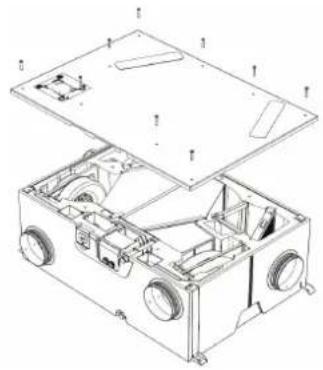
- Every 24 months: remove dust from inside of the heat recovery unit with a vacuum cleaner.
H R:

ST:

H R :

T:

- Every 6 months: clean the extraction spigots of kitchen and bathroom with warm water and soap.
8. PUTTING OUT OF SERVICE AND RECYCLING

EEC legislation and our consideration of future generations mean that we should always recycle materials where possible; please do not forget to deposit all packaging in the appropriate recycling bins. If your device is also labeled with this symbol, please take it to the nearest Waste Management Plan at the end of its servicable life.
9. ECODESIGN TECHNICAL SHEET

Ecodesign Commission regulation (EU) N°1253/2014 of July 2014 Information requirements (Annex V) ORKA ST
| a Trade mark S&P | ||
| b Identifi er 5153832900 | ||
| c SEC average climate (kWh/(m 2 .an)) -20,5 | ||
| SEC class D | ||
| SEC cold climate (kWh/(m 2 .an)) -51,4 | ||
| SEC warm climate (kWh/(m 2 .an)) -0,2 | ||
| d Typology RVU bidirectional | ||
| e Type of drive 3 speeds | ||
| f Type of HRC Recuperative | ||
| g Thermal effi ciency (%) 65 | ||
| h Maximum flow rate (m 3 /h) | 220 | |
| i Electrical power input at maximum flow rate (W) | 125,0 | |
| j Sound power level (LWA) | 50 | |
| k Reference flow rate (m 3 /s) | 0,043 | |
| l Reference pressure difference (Pa) | 60,0 | |
| m SPI (W/m 3 /h) | 0,539 | |
| n Control factor | 1 | |
| Control typology | Manual | |
| o Maximum internal leakage for BVU (%) | 6 | |
| Maximum external leakage for BVU and UVU (%) | 4 | |
| p Mixing rate for BVU without duct connection (%) | Not apply | |
| q Position of visual fi lter warning | Remote control | |
| Description of visual fi lter warning | Pilot light | |
| r | Instructions to install supply grilles | Not apply |
| Instructions to install exhaust grilles | Not apply | |
| s Internet address | www.solerpalau.com | |
| t | Airflow sensitivity to pressure variation | Not apply |
| u Indoor/outdoor air tightness (m 3 /h) | Not apply | |
| v | Annual electricity consumption - Average climat (kWh/a) | 720 |
| Annual electricity consumption - Warm climat (kWh/a) | 675 | |
| Annual electricity consumption - Cold climat (kWh/a) | 1257 | |
| w | Annual heating saved - Average climat (kWh/a) | 37,9 |
| Annual heating saved - Warm climat (kWh/a) | 17,1 | |
| Annual heating saved - Cold climat (kWh/a) | 74,1 | |


- CONTENTS
- GENERAL INFORMATION
- INTRODUCTION
- WARRANTY AND LIABILITY
- WARRANTY
- THE WARRANTY DOES NOT COVER
- LIABILITY
- SAFETY
- GENERAL HEALTH AND SAFETY STANDARDS
- TECHNICAL INFORMATION
- DESCRIPTION
- NEW FRESH AIR INLET
- SUPPLY FRESH AIR INTO THE BUILDING
- EXTRACT AIR FROM THE BUILDING
- BY PASS
- ALARM FI LTER CHANGE
- DIMENSIONAL CHARACTERISTICS
- INSTALLATION
- SPIGOT ARRANGEMENT ∅ 80 MM
- 3.A. MOUNTING IN A FALSE CEILING
- 3.B. MOUNTING IN A FLOOR
- SAMPLE "MIXED DISTRIBUTION" ASSEMBLY
- SAMPLE "PLENUM DISTRIBUTION" ASSEMBLY
- SAMPLE "DISTRIBUTION" ASSEMBLY
- CHARACTERISTICS AND ELECTRICAL CONNECTION
- CONTROL OF ORKA
- 5.1A. AIRFLOW SELECTION
- 5.1B. ALARM CHANGE FILTERS
- DURING USE
- LOW AIRFLOW
- PEAK AIRFL OW
- BY-PASS (ON/OFF)
- COMMISSIONING THE ORKA
- MAINTENANCE
- PUTTING OUT OF SERVICE AND RECYCLING
- ECODESIGN TECHNICAL SHEET
Brand : Soler & Palau
Model : ORKA HR D150
Category : Ventilation