
Spot Lift PRO MOB - Car lift GYS - Free user manual and instructions
Find the device manual for free Spot Lift PRO MOB GYS in PDF.
User questions about Spot Lift PRO MOB GYS
0 question about this device. Answer the ones you know or ask your own.
Ask a new question about this device
Download the instructions for your Car lift in PDF format for free! Find your manual Spot Lift PRO MOB - GYS and take your electronic device back in hand. On this page are published all the documents necessary for the use of your device. Spot Lift PRO MOB by GYS.
USER MANUAL Spot Lift PRO MOB GYS
natural_image
Technical line drawing of a SPOT LIFT PRO MO robotic vehicle with articulated arms and wheels (no text or symbols on the diagram itself)SPOT LIFT PRO MOB
FR 2-5 / 6-12 / 36-40
EN 2-5 / 13-18 / 36-40
ES 2-5 / 19-22 / 36-40
RU 2-5 / 23-30 / 36-40
IT 2-5 / 30-36 / 36-40
NL 2-5 / 37-43 / 36-40
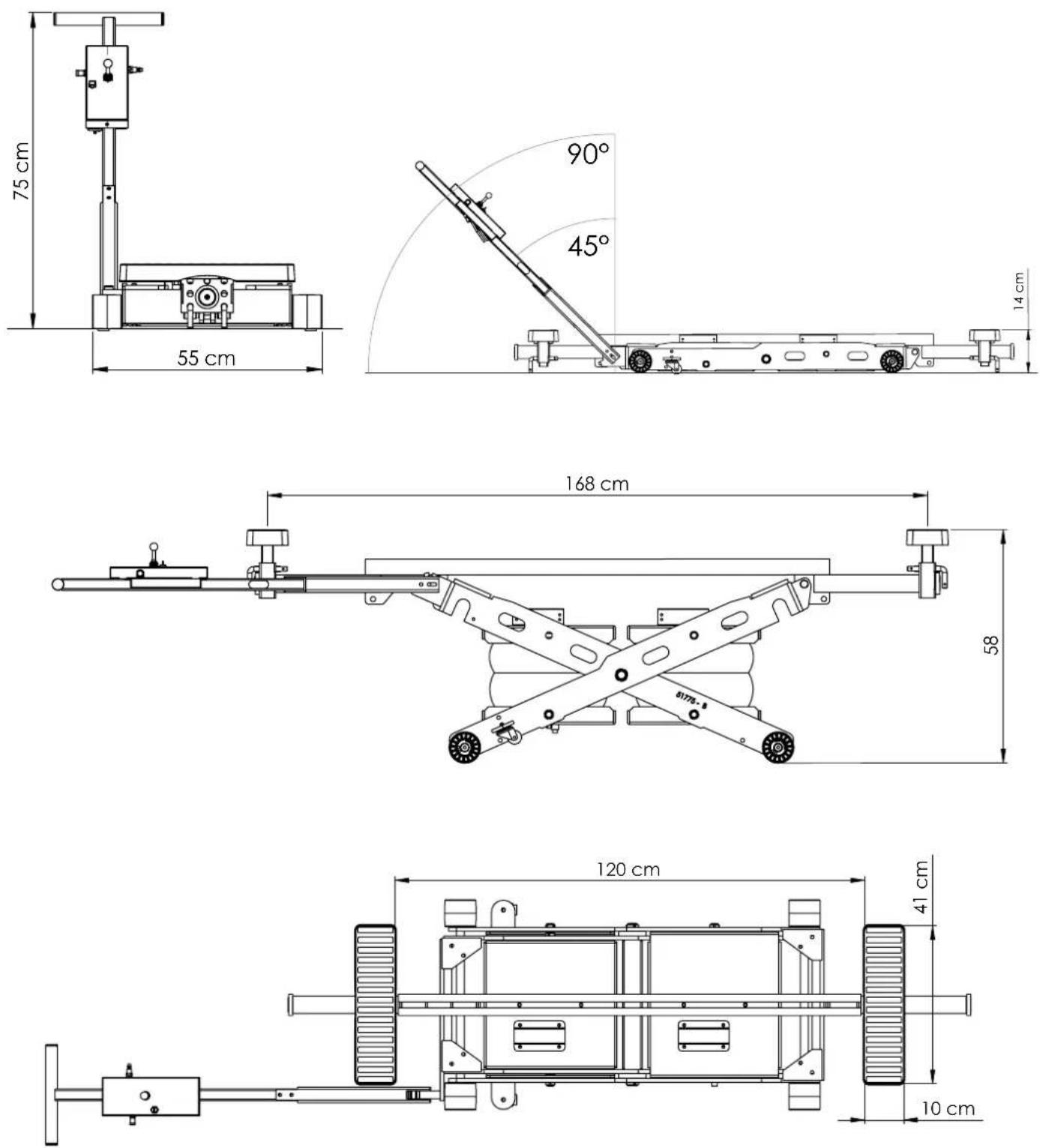
DIMENSIONS / DIMENSIONES / PA3MEPЫ / DIMENSIONI / AFMETINGEN /
PIÈCES DE RECHANGE / SPARE PARTS / ERSATZTEILE / ЗАПАСНЫЕ ЧАСТИ / PIEZAS DE RECAMBIO / ONDERDELEN

text_image
Exploded view diagram of a mechanical assembly with numbered components for identification| 1 56114 | Patin caoutchouc antidérapantRubber padРезиновая подошва против скольженияSoporte de caucho antideslizantePattino in gomma antiscivoloRubberen antislip steunblok | 24 71113 | Air Jack D300 - Pneumatic ∅ 300Air Jack D300 - Pneumatic ∅ 300Air Jack D300 - Neumático ∅ 300Пневматический домкрат D300 - ∅ 300Jack aria D300 - Pneumatico ∅ 300Air Jack D300 - Pneumatisch ∅ 300 | |
| 2 99691ST | Patin rectangle acier épaisseur 5 mm5 mm rectangular steel padПрямоугольные опорные подошвы из стали5 ммSoporte rectangular de acero de 5mm de grosorPattino rettangolare acciaio spessore 5 mmRechthoekig stalen steunblok (5 cm. dik) | 25 99683 | Capot protection clapet anti retourCheck valve protectionCapó de protección de válvula antirretornoЗащитный корпус обратного клапанаCoperchio di protezione valvola anti ritornoTerugslagklep beschermkap | |
| 3 99688ST | Poutre de centrale acierCentral steel beamTrave centrale acciaioЦентральная стальная балкаТоре de viga central de aluminio Viga central de aceroCentrale stalen balk | 26 71782 | Clapet unidirectionnel piloté G1/4 D6Unidirectional check valve G1/4 D6Válvula unidireccional controlado G1/4 D6Управляемый клапан одного направления G1/4 D6Valvola unidirezionale controllata G1/4 D6Eenrichtingsklep bestuurd G1/4 D6 | |
| 4 91018 | Butée poutre centrale aluCentral aluminium beam stopTope de viga central de aluminioАлюминиевый упор центральной балкиFermo trave centrale alluminioEindstuk centrale balk aluminium | 27 | 71786 71787 | |
| Tuyau d'air ∅ 6Air hose ∅ 6Conducto de aire ∅ 6Трубка для воздуха ∅ 6Tubo d'aria ∅ 6Luchtslang ∅ 6 | Tuyau d'air ∅ 4Air hose ∅ 4Conducto de aire ∅ 4Трубка для воздуха ∅ 4Tubo d'aria ∅ 4Luchtslang ∅ 4 | |||
| 5 31055 | Aimant et support Ferrite ∅35Ferrite magnet and holder ∅35Imán de ferrita y soporte ∅35Ферритовый магнит и держатель ∅35Magnete in ferrite e supporto ∅35Ferrietmagneet en houder ∅35 | 28 90662ST | Axe D20 x 40Axle D20 x 40Eje D20 x 40Ось D20 x 40Perno D20 x 40As D20 x 40 | |
| 6 41285 | Vis mx M8x6 STHC H4 bout plat inox A2 din 913Screw mx M8x6 flat end stainless steel din 913Tornillo mx M8x6 STHC cabeza plana inoxi-dable din 913Винт mx M8x6 STHC с плоским концом из нержавейки din 913Vite piatta mx M8x6 STCH inox din 913Schroef mx M8x6 STHC platte kop inox din 913 | 29 42101 | Circlips ∅ 25Circlips ∅ 25Anilla seeger ∅ 25Стяжное кольцо ∅ 25Anello di tenuta ∅ 25Borgringen ∅ 25 | |
| 7 71478 | Raccord airAir connectorConector de aireРазъем для воздухаRaccordo ariaAansluiting lucht | 30 56209 | Roue delrinDelrin wheekRueda delrinДелриновое колесоИuota delrinDelrin wiel | |
| 8 71788 | Prolongateur G1/8Extension G1/8Prolongador G1/8Надставка G1/8Prolunga G1/8Verlengstuk G1/8 | 31 71377 | Roue pivot D35 H50Pivot wheels D35 H50Rueda giratoria D35 H50Колесо на вертлюге D35 H50Ruota girevole D35 H50Zwenkwiel D35 H50 | |
| 9 55138 | Raccord banjo ∅ 6Banjo fitting ∅ 6Conector banjo ∅ 6Соединение банджо ∅ 6Raccordo banjo ∅ 6Banjo aansluiting ∅ 6 | 32 41185 | Écrou à encoches M15x100 avec freinSlotted nut with cotter pin M15x100Tuerca con muescas M15x100 con frenoСтопорная гайка с прорезями M15x100Dado a tacche M15x100 con frenoBorgmoer M15x100 met rem | |
| 10 71789 | DistributeurDistributorDistribuidorРаспределительDistributoreDistributeur | 33 90664ST | Axe épaulé D20 x 31Shoulder axle D20 x 31Eje D20 x 31Ось с буртом D20 x 31Cerniera D20 x 31Gaffelpen D20 x 31 | |
| 11 71636 | Soupape de sécurité 5.5 barsSafety valve 5.5 barsSolapa de seguridad 5.5 barsПредохранительный клапан 5.5 барValvola di sicurezza 5.5 barsVeiligheidsklep 5.5 bars | 34 90661ST | Axe D25 x 47Axle D25 x 47Eje D25 x 47Ось D25 x 47Perno D25 x 47As D25 x 47 | |
| 12 71784 | Raccord droit femelle G1/4 D6Right female fitting G1/4 D6Conector recto hembra G1/4 D6Прямое стыковочное соединение "мама" G1/4 D6Raccordo destro femmina G1/4 D6Knelkoppeling recht vrouwelijk G1/4 D6 | 35 41184 | Écrou à encoches M15x100 avec freinSlotted nut with cotter pin M15x100Tuerca con muescas M15x100 con frenoСтопорная гайка с прорезями M15x100Dado a tacche M15x100 con frenoBorgmoer M15x100 met rem | |
| 13 71781 | Venturi D6Venturi D6Venturi D6Вентури D6Venturi D6Venturi D6 | 36 | FAB 037ST | |
| 14 71480 | Raccord plastique Y femelle D6Famale plastic Y fitting D6Conector plástico Y hembra D6Пластиковый Y разъем "мама" D6Raccordo plastica Y femmina D6Kunststoffen verbindingsstuk Y vrouwelijk D6 | 37 99094ST | Support Patin double acier épaisseur 5mmSteel double pad support 5mmSoporte doble acero grosor 5mmДвойная подпорка для подошвы из стали толщиной 5mMSupporto Pattino doppio acciaio spessore 5mmHouder steunblokken dubbel staal 5mm dik | |
| 15 71790 | Sélecteur 2 positions2 positions switchSeleccionador 2 posiciones2-позиционный переключательSelettore 2 posizioniKeuzeschakelaar 2 posities | 38 99737 | Supports roulettes épaisseur 5mmWheel supports 5mmsoporte ruedas grosor 5mMПодставка для колесиков толщиной 5mMSupporti ruote spessore 5mmWielsteunen 5mm | |
| 16 55231 | Raccord plastique Y femelle D4Famale plastic Y fitting D4Conector plástico Y hembra D4Пластиковый Y разъем «мама» D4Raccordo plastica Y femmina D4Kunststoffen verbindingsstuk Y vrouwelijk D4 | 39 Fab 077 | Broche sécurité acier ∅ 12 mm (L = 186 mm)Steel safety pins ∅ 12 mm (L = 186 mm)Broche de seguridad acero ∅ 12 mm (L = 186 mm)Стержень безопасности из стали ∅ 12 mm (D = 186 mm)Spilla di sicurezza acciaio ∅ 12 mm (L = 186 mm)Stalen veiligheidspin ∅ 12 mm (L = 186 mm) | |
| 17 55228 | Mini régulateur de pression G1/8Mini regulator G1/8Mini Druckregler G1/8 | 40 91019ST | Axe poignée acier ∅ 20 mmSteel handle axle ∅ 20 mmEje con mango de acero ∅ 20 mmОсь рукоятки из стали ∅ 20 ммPerno impugnatura acciaio ∅ 20 mmAs stalen handvat ∅ 20 mm | |
| 19 43101 | Embout rond à lamellesRound slatted end capRunde Lamellenspitze | 41 51785 | Poignée acier épaisseur 5 mmSteel handle 5 mmMango de acero grosor 5 mmРукоятка из стали толщиной 5 ммImpugnatuta acciaio spessore 5 mmStalen greep 5 mm dik | |
| 20 99700 ST | Levier de commandeControl leverPalanca de mandoРычаг управленияLeva di comandoBedieningshendel | 42 71780 | Roue pivotante polyamidePolyamide turning wheelRueda giratoria de poliamidaПоворотное колесо из полиамидаRuota girevole polyammidePolyamide zwenkwiel | |
| 21 99699 | Carter de protectionProtective casingCarcasa de protecciónЗащитный кожухCarter di protezioneBeschermkap | 43 42099 | Goupille à billeLocking pinPasador con bolaШтифт с шариковым фиксаторомCoppiglia a sferaVergrendelpen | |
| 22 99697 | Capot commandeControl panelCubierta de controlКорпус управленияСоперchio comandoKap besturing | 44 43104 | Gaine spiraléeSpiral sheathFunda espiralСпиральная оболочкаGuaina a spiraleSpiraalslang | |
| 23 51234ST | Articulation levierLever jointArticulación de palancaКолено рычага из оцинкованной сталиArticolazione levaScharnierhefboom | 45 55232 | Raccord en «T» D6Connector «T» D6Conector «T» D6Raccord «T» D6Соединение банджо «T» D6Raccordo «T» D6aansluiting «T» D6 | |
natural_image
Industrial machinery setup with a metal clamp and mechanical components (no visible text or symbols)
natural_image
Exploded view diagram of a toy car with exploded parts and mounting hardware (no text or labels)ESPACE DE SÉCURITÉ
natural_image
Mechanical assembly diagram showing a lever mechanism and a separate cylindrical component labeled A (no text or symbols present)natural_image
Mechanical assembly diagram showing two crossed arms with circular checkmark indicators (no text or symbols)
natural_image
Mechanical assembly diagram showing a lever and shaft assembly (no text or symbols visible)OUI
text_image
Diagram showing a mechanical or optical setup with two smiley faces and labeled dimensions, likely illustrating a physics or engineering concept.NON
natural_image
Mechanical diagram showing a lever system with two smiling faces and a central rotating shaft (no text or symbols)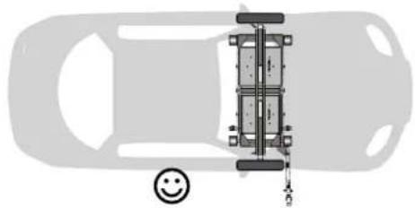
natural_image
Top-down diagram of a car showing its structural components including a vertical frame, wheels, and a smiley face (no text or symbols)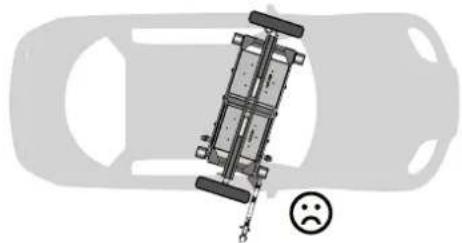
natural_image
Top-down view of a car with a suspended vehicle and a sad face emoji (no text or symbols)
natural_image
Mechanical assembly diagram showing a linkage mechanism with a separate pulley attachment (no text or symbols visible)
natural_image
Mechanical assembly diagram showing a linkage mechanism with pulleys and a wheel (no text or symbols visible)4/ DESCENTE
text_image
Technical diagram of a mechanical device with numbered components for identificationANOMALIES, CAUSES, REMÈDES
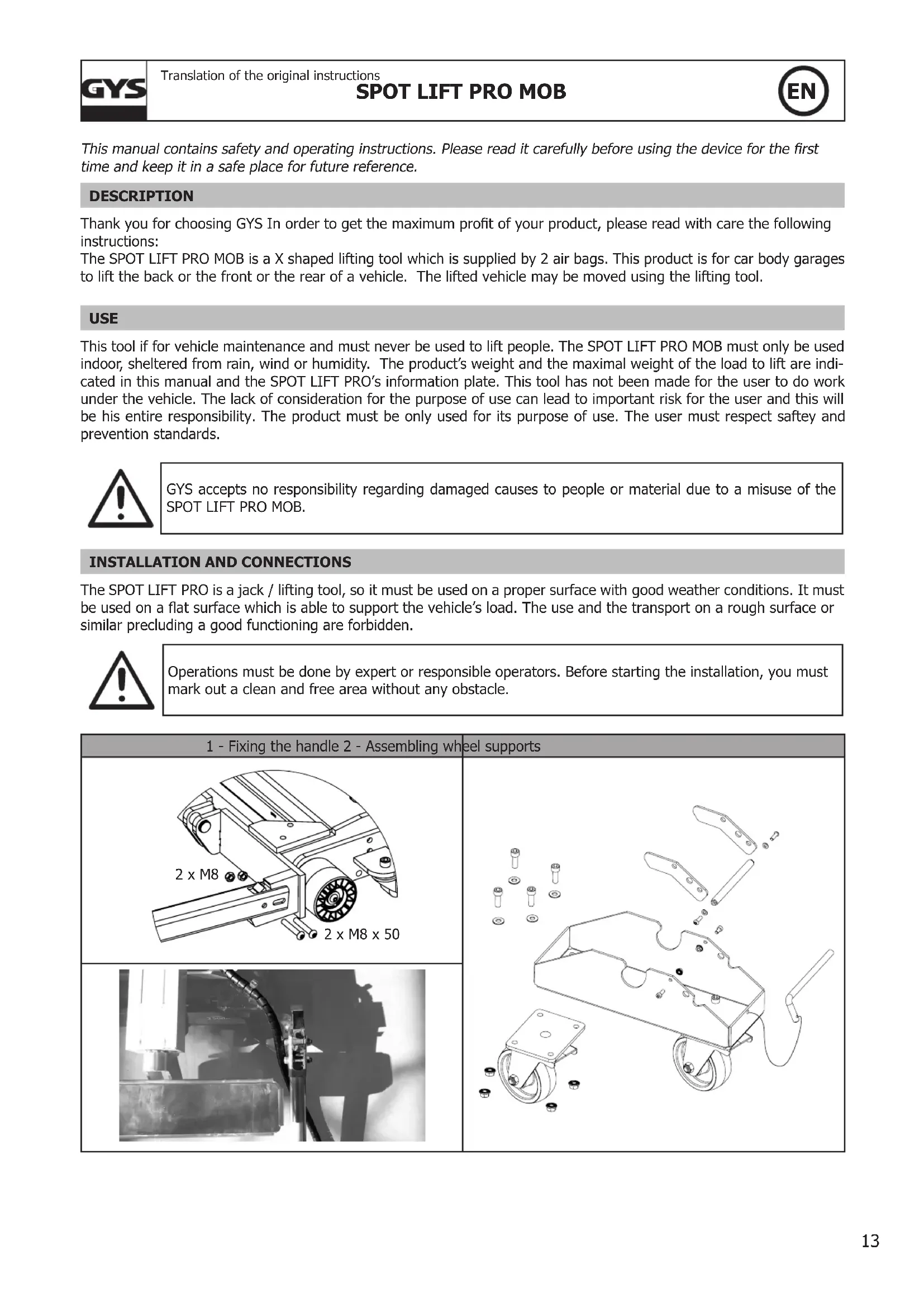
This manual contains safety and operating instructions. Please read it carefully before using the device for the first time and keep it in a safe place for future reference.
DESCRIPTION
Thank you for choosing GYS In order to get the maximum profit of your product, please read with care the following instructions:
The SPOT LIFT PRO MOB is a X shaped lifting tool which is supplied by 2 air bags. This product is for car body garages to lift the back or the front or the rear of a vehicle. The lifted vehicle may be moved using the lifting tool.
USE
This tool if for vehicle maintenance and must never be used to lift people. The SPOT LIFT PRO MOB must only be used indoor, sheltered from rain, wind or humidity. The product's weight and the maximal weight of the load to lift are indicated in this manual and the SPOT LIFT PRO's information plate. This tool has not been made for the user to do work under the vehicle. The lack of consideration for the purpose of use can lead to important risk for the user and this will be his entire responsibility. The product must be only used for its purpose of use. The user must respect safety and prevention standards.
GYS accepts no responsibility regarding damaged causes to people or material due to a misuse of the SPOT LIFT PRO MOB.
INSTALLATION AND CONNECTIONS
The SPOT LIFT PRO is a jack / lifting tool, so it must be used on a proper surface with good weather conditions. It must be used on a flat surface which is able to support the vehicle's load. The use and the transport on a rough surface or similar precluding a good functioning are forbidden.

Operations must be done by expert or responsible operators. Before starting the installation, you must mark out a clean and free area without any obstacle.
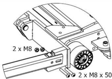
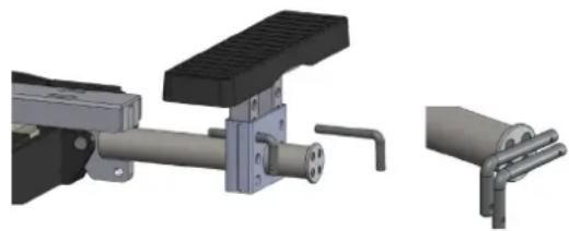
1 - Fixing the handle 2 - Assembling wheel supports
text_image
2 x M8 2 x M8 x 50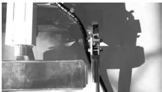
natural_image
Close-up of a mechanical assembly with blurred background (no visible text or symbols)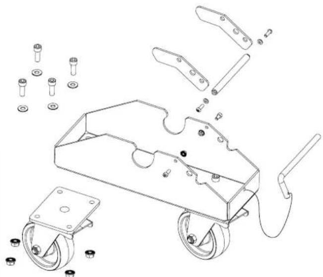
natural_image
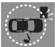
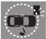
Technical line drawing of a car chassis with exploded view and component labels (no text or symbols)SAFTEY AREA
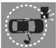
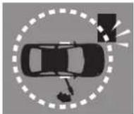
For an optimal safety, it is recommended to make sure that any other objects or walls are away. Any handling work must be done with care from the operator. Nobody must be stand in the safety area. In order to secure the operator, the command remote box must be situated at a distance where the operator can get away easily in case of emergency.
INDIVIDUAL PROTECTION
The operator must be equipped following prevention standards and must take the necessary actions to maintain safety. During manoeuvres, the operator must protect his safety and people safety. The operator must take into consideration all the recommendations quoted in this manual.
INSTALLATION
Once the product out of is packaging, assembled and on the floor, make a try to check the good functioning. The command panel is attached to the lever.
Start and verification (attempt)
- Screw the compressed air connexion tip on the command remote box and connect it to the compressed air circuit.
- Check that the pressure is correct (Max 8 bar).
- Check that there is no air leakage and that the cable is not damaged.
LIFTING CHECK:
After performing the verifications listed above, push the joystick up continuously in order to raise the SPOT LIFT PRO MOB. Once the maximum height is reached, release the joystick in order to put it back on its initial position. Disconnect the air supply to make sure that the SPOT LIFT PRO MOB does not lower.
LOWERING CHECK:
Before any operation, make sure that nothing is under the SPOT LIFT PRO.
To get the product to lower, check that the air supply is connected and continuously push the joystick down. The SPOT LIFT PRO will go down to its lowest point.
If these 2 steps have been successful, the product is ready to use.
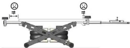
INSTRUCTIONS
WARNING: Before lifting a vehicle, make sure that the hand brake is released, that the vehicle is on neutral and that tyres pressure is enough to maintain the vehicle in balance.
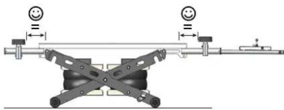
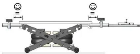
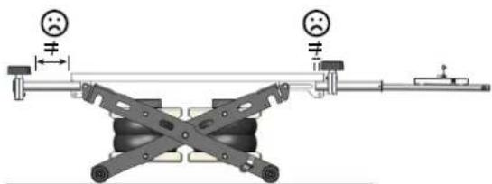
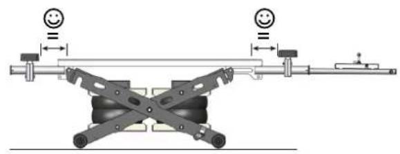
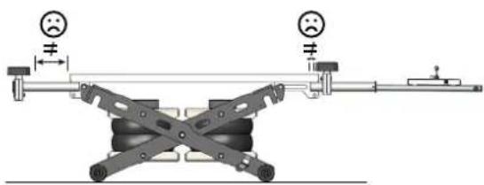
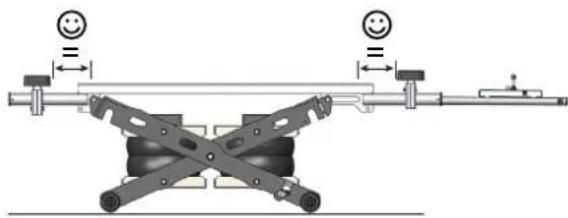
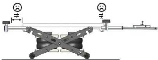
Position the SPOT LIFT PRO MOB under the vehicle and centre it widthwise. Extend arms until that the rubber pads are in position, in accordance with the car manufacturer's recommendations. Pads are height adjustable. Fix the height with the small bar in order to be as close as possible of the lowest part of the vehicle. Once the tool is positioned, proceed with the lifting operation :
natural_image
3D mechanical assembly diagram showing a lever mechanism with no visible text or symbolsCheck that no bulky objects are in the safety area
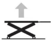
- Push the joystick up until the height is sufficient
- Stop the lifting by releasing the joystick.
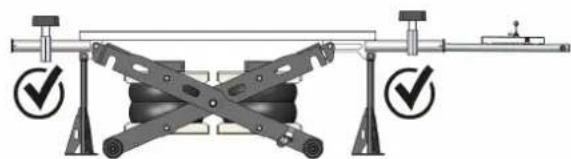
After lifting the vehicle, it must be support by 2 safety links, which must be locked using the safety pins. (Do not go under the vehicle to position them)
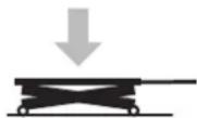
- Push the joystick down fo the SPOT LIFT PRO MOB rests on the safety links, which will secure the load.
- Disconnect the air hose from the control panel so you may move around the vehicle freely.
natural_image
Mechanical assembly diagram showing two crossed arms with circular checkmark indicators (no text or symbols)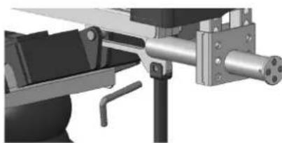
natural_image
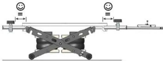
Mechanical assembly diagram showing a lever mechanism with no visible text or symbolsYES
text_image
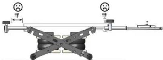
Diagram of a mechanical device with two smiley faces and labeled dimensions, showing alignment and assembly components.NO
natural_image
Mechanical diagram showing a lever system with two smiling faces and a central cross-shaped component (no text or symbols)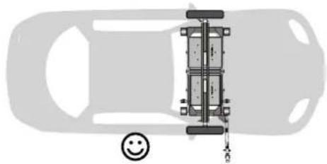
natural_image
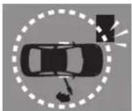
Top-down diagram of a car showing its structural components and a smiley face icon (no text or symbols)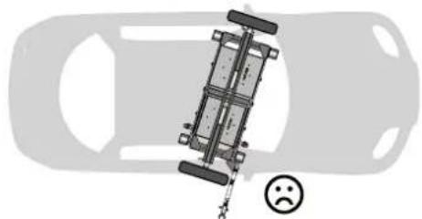
natural_image
Top-down view of a car with a sad face emoji and a vehicle chassis diagram (no text or symbols)
GYS accepts no responsibility in case of damaged causes to people if the operator does not respect recommendations.
2/ WORKING POSITION
Once the operation is done and before starting your work on the vehicle, make sure you have check the stability of the vehicle on the SPOT LIFT PRO.
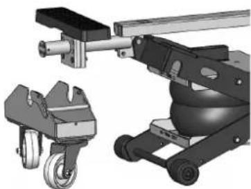
3/ MOVING THE VEHICLE
Remove the safety links.
Place the wheel supports near the pads and lock it.
To lower the SPOT LIFT PRO MOB, reconnect the air supply and push the jotstick down until the support's wheels touch ground.
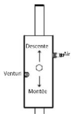
At this stage, activate the «venturi» function, then push the joystick
down so the SPOT LIFT PRO MOB scissors will go back up.
Safely move the vehicle.
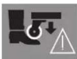
Wear safety shoes.
To resume work, deactivate the «venturi» function then push the joystick up to lift the car.
Remember to put the safety links back.
To remove the wheel supports, Unlock the safety lever and remove the pin.
natural_image
Mechanical assembly diagram showing a linkage mechanism with wheels and a separate mechanical component (no text or symbols visible)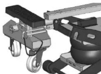
natural_image
Mechanical assembly diagram showing a linkage mechanism with levers and pulleys (no text or symbols visible)4/ LOWERING
Remove the safety links.
To get the product down, push continuously the joystick down. The joystick always comes back to its initial position in order to make sure that all the operations are intentional.

Before lowering the SPOT LIFT PRO MOB, make sure that no electric cable or object are going through the scissors.
SAFETY MEASURE
- The SPOT LIFT PRO must be used by trained and authorized people. Moreover, they must have read this user manual. It must be read carefully before using the SPOT LIFT PRO MOB. It is forbidden to lift people wit this product.
- Check the load, especially when lifting, while ensuring there is no anomaly. In the event of an issue, the SPOT LIFT PRO MOB must go down as soon as possible and positioned correctly.
- Clean the vehicle supporting surface, make sure that there is no oil or grease which may maje the vehicle slip
- This product is solely a lifting tool. After lifting the vehicle, it must be supported by safety links.
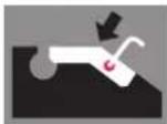
- Do not put the pads on an area next to airbags sensors or on an area covered with plastic.
- Do not put the pads on an area covered with plastic.
- The tool is equipped with a safety valve which opens itself when the pressure inside the air chambers is too high (5.5 bar)
- Check that the input pressure is ≤ 8 bar. If necessary, use a pressure regulator.
- Once the work is done, systematically lower the load down to the ground so the SPOT LIFT PRO MOB does remain under a full load for a long period of time.
- The device must not be used in an explosive atmosphere and it preferable to not work close to a heat source (risque of explosion in the air chambers).
- It is forbidden to use the device on a boat (stability issues).
- It is forbidden to use spare parts other than the ones certified by GYS.
- Do not lift loads other than the ones the SPOT LIFT PRO MOB is designed to lift.
- If in doubt about the solidity of the vehicle (rust) - Do not lift the vehicle.
- Do not use in highly humid environments. The device must not be submerged. Water going ionside the device may damage the pneumatic system.
Recommendation : It is recommended to use a receiver drier on the compressor, to reduce the risks of humidity.
- Do not perform any modifications on the machine
CONTROLS AND MAINTENANCE
Inspections and maintenance work are carried out by authorised personnel at the specified maintenance intervals. Do not use water or flammable liquids for cleaning. The following points must be observed to ensure a long service life and proper use of the pneumatic jack:
- Only original spare parts may be used «Spare parts (page 44)».
- The recommended maintenance intervals must be observed «Maintenance table (page 16)»
- For maintenance work that is not covered or indicated in the operating instructions, contact your dealer and/or the GYS after-sales service.
Clean the jack at least once a week to remove all dust and dirt that could degrade the proper functioning of the product in the long term. Use self-cleaning cloths. Do not use any water nor flammable or corrosive liquids.
Only carry out maintenance work when the jack is raised and held on its 2 unloaded supports while removing the air hose.
MAINTENANCE TABLE
| Maintenance intervals | Task Remarks | |
| Monthly | Check, clean and lubricate all moving parts, including the axes and sliding surfaces of the scissors.Check the condition of the rubber pads and clean them.Check the bellows and pneumatic hoses for damage. Visual inspection and waterproofing control. Check the surfaces of the bellows for impurities, clean and treat it.Check the function and tightness of the pressure relief valve.Check the fixing of the plastic clamps and the beam fasteners on chisel and platters. | Refer to «Check and Lubrication Point (page 17)».Remove if necessary.Refer to «Bellows Properties and Lifetime (page 17)».Without load, with an inlet pressure of between 6 and 7 bar, lift the jack up to the maximum until you hear the exhaust noise of the valve.Replace plastic clamps if necessary. |
| Annual | «Regular safety check (page 40)» | For the test protocol, refer to «Regular safety check (page 47)». |
| Every 5 years of service | Replace the complete set of pneumatic hoses. | Refer to the exploded view. «Spare parts (page 44)» |
Properties and life span of bellows:
Bellows are flexible elements made of an ageing rubber casing. They must be checked particularly carefully.
Advice for a long life:
- Use dry, non-lubricated compressed air.
- Protect the bellows from UV radiation (e. g. from welding or UV drying).
- Avoid the use of chemicals.
- Protect the bellows from mechanical damage (perforations, etc.).
- Observe the maintenance and care instructions «see chapter Lubrication points (page 17)».
It is imperative to replace damaged or cracked bellows. Only original manufacturer's parts are allowed.
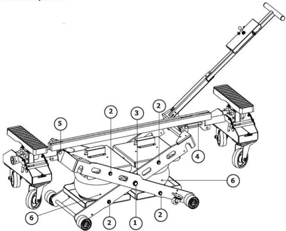
Check and lubrication points :
text_image
Technical diagram of a mechanical device with numbered components for identification| N° | Description Lubrication and control points | |
| 1 | Scissor axis (L/R) • Check that the | lock nuts are securely fastened• Lubricate the shafts |
| 2 | Plate axis (L/R) | |
| 3 | Interface of the 2 scissors • Lubricate the rubbing parts | |
| 4 | Internal chisel slide • Check that the circlip is securely fastened• Lubricate the axle and slide | |
| 5 | Fixed axis external scissors | |
| 6 | Bellows | • Check the bellows for damage• Check the tightness of the screws of the top and bottom plate fixing• Treat the surface of the bellows with a suitable rubber care product |
SECURITY CHECK
Security screening is required for the SPOT LIFT PRO Mob operational security guarantee.
It must be done at regular intervals:
Use of the «Regular safety check (page 40)» form.
Make a copy of the SPOT LIFT PRO Mob status report and attach it to the operating instructions.
Regular safety checks must be carried out by an authorised person. It is recommended to perform maintenance simultaneously.
TROUBLESHOOTING
The chart below indicates the issues that can be observed during the use of the product. If the problem observed does not appear in the table below, stop using the product and call immediately your distributor in order to know the procedure to follow.
| TROUBLESHOOTING CAUSES | SOLUTIONS | |
| The joystick is activated but the product does not lift up. | Excessive charge | Check vehicle's weight and follow manufacturer instructions. |
| Insufficient air pressure for the charge. | Check that the air supply is ≤ 8 bars. | |
| Make sure the air pipe is not tangled. | ||
| Air leaks during the lifting. | Security valve faulty Change safety valve | |
| Air pressure too important Adjust air pressure (7/8 bars max) | ||
| The product goes down by itself when the joystick is on its initial position. | Check that archambers are not breached. | Change archambers. |
| Leak inside the pneumatic circuit | Check air circulation, connections and pneumatic control.(cf. pneumatic circuit p.36) | |
| The products stops while doing down. | There are obstacles between scissors of the machine. | Remove the obstacle. |
DESACTIVATION
Any equipment that appears damaged in any way, does not operate normally, or is missing parts should be taken out of service immediately by removing the air connection from the control box. Do not use the unit if you notice parts are broken, bent or cracked.
START-UP
The jack must be disposed of in accordance with current environmental and country disposal guidelines.
WARRANTY
The warranty covers faulty workmanship for 2 years from the date of purchase (parts and labour).
The warranty does not cover:
- Transit damage.
- Normal wear of parts (eg. : cables, clamps, etc..).
- Damages due to misuse (power supply error, dropping of equipment, disassembling).
- Environment related failures (pollution, rust, dust).
In case of failure, return the unit to your distributor together with:
- The proof of purchase (receipt etc ...)
- A description of the fault reported
natural_image
Industrial machinery setup with a metal clamp and cylindrical component (no visible text or symbols)
natural_image
Exploded view diagram of a toy car with exploded components and wheels (no text or labels)natural_image
Mechanical assembly diagram showing a lever mechanism with attached components (no text or symbols visible)natural_image
Mechanical linkage system diagram with two circular checkmark indicators (no text or symbols)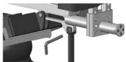
natural_image
Mechanical assembly diagram showing a shaft and mounting bracket (no text or symbols visible)sí
natural_image
Mechanical diagram showing a lever system with two smiling faces and a central rotating wheel (no text or symbols)No ▲
natural_image
Mechanical linkage diagram showing two arms with a central cross-shaped component and two smiling faces above (no text or symbols)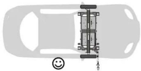
natural_image
Top-down diagram of a car showing its front suspension system with a smiley face icon (no text or symbols)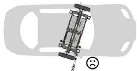
natural_image
Top-down view of a car with a suspended vehicle and a sad face emoji (no text or symbols)
natural_image
Mechanical assembly diagram showing a wheeled cart with wheels and a mechanical lever (no text or symbols visible)
natural_image
Mechanical assembly diagram showing a lever mechanism with pulleys and weights (no text or symbols visible)4/ DESCENSO
natural_image
Industrial machinery setup with a metal frame and clamping mechanism (no visible text or symbols)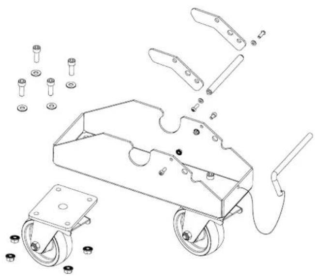
natural_image
Exploded view diagram of a toy car chassis with exploded components and mounting holes (no text or labels)ЗОНА БЕЗОПАСНОСТИ
natural_image
Mechanical assembly diagram showing a lever mechanism with two components and a separate bracket (no text or symbols)natural_image
Technical illustration of a mechanical assembly with two views: one showing a lever mechanism and the other showing a cylindrical component (no text or symbols present)ДА
natural_image
Mechanical assembly diagram showing a rotating platform with two smiling circular components and directional arrows (no text or labels)HET
natural_image
Mechanical linkage diagram showing two connected components with circular head symbols (no text or labels)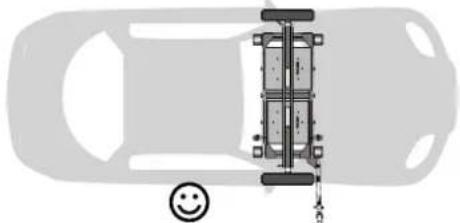
natural_image
Top-down diagram of a car showing its front suspension system with a smiley face icon (no text or symbols)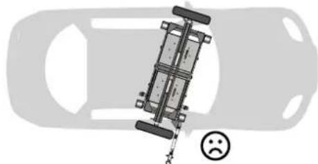
natural_image
Top-down view of a car with a suspended vehicle and a sad face emoji (no text or symbols)
natural_image
Mechanical assembly diagram showing a linkage mechanism with wheels and a separate mounting bracket (no text or symbols)natural_image
Mechanical assembly diagram showing a linkage mechanism with wheels and components (no text or symbols visible)4/ ОПУСКАНИЕ
text_image
Technical diagram of a mechanical device with numbered components for identificationnatural_image
Close-up of a mechanical assembly with blurred background (no visible text or symbols)
natural_image
Exploded view diagram of a toy car chassis with exploded parts and mounting hardware (no text or labels)SPAZIO DI SICUREZZA
natural_image
Mechanical assembly diagram showing a lever mechanism with attached components (no text or symbols visible)natural_image
Mechanical linkage system diagram with two checkmark indicators (no text or symbols present)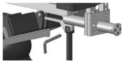
natural_image
Mechanical assembly diagram showing a shaft and housing component (no text or symbols visible)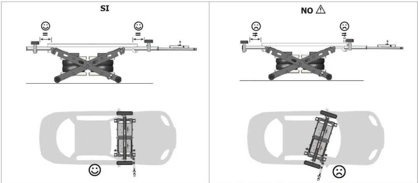
text_image
SI NO ▲
natural_image
Mechanical assembly diagram showing a linkage mechanism with wheels and a separate mechanical component (no text or symbols visible)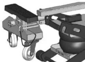
natural_image
Mechanical assembly diagram showing a lever mechanism with pulleys and weights (no text or symbols visible)natural_image
Close-up of industrial machinery components with no visible text or symbols
natural_image
Technical line drawing of a wheeled cart with exploded view and component labels (no text or symbols)VEILIGHEIDSZONE
natural_image
3D mechanical assembly diagram showing a lever, valve, and housing components (no text or symbols)natural_image
Mechanical linkage system with two circular checkmark indicators (no text or symbols)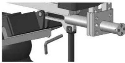
natural_image
Mechanical assembly diagram showing a shaft, frame, and housing components (no text or symbols visible)JA
natural_image
Mechanical assembly diagram showing a rotating platform with two smiling face indicators (no text or symbols)NEE
natural_image
Mechanical diagram showing a lever system with two smiling faces and a central cross-shaped component (no text or symbols)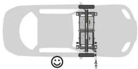
natural_image
Top-down diagram of a car with a vertical suspension bridge and a smiley face icon (no text or symbols)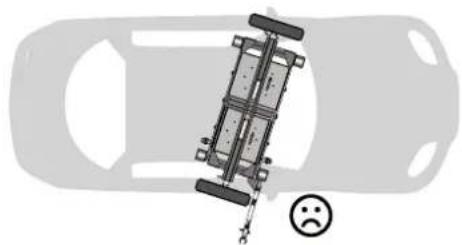
natural_image
Top-down view of a car with a suspended vehicle and a sad face emoji (no text or symbols)
natural_image
Mechanical assembly diagram showing a linkage mechanism with wheels and a separate mounting bracket (no text or symbols)natural_image
Mechanical assembly diagram showing a lever mechanism with weights and components (no visible text or symbols)4/DALEN
text_image
Technical diagram of a mechanical device with numbered components for identificationINSTRUCTIES AFVALVERWERKING
| Verification phase OK NOK Verification Note | ||||
| Technical table on the jack | ||||
| Load capacity in the table | ||||
| Network pressure in the panel and on the control unit | ||||
| Instructions for use (original) | ||||
| Signalling up / down of the jack on the control unit | ||||
| Tight fastening of all bearing screws | ||||
| Tightening of nuts on all axes | ||||
| Condition of pneumatic lines and ductwork | ||||
| Safety valve set at 5.5 bar | ||||
| Mains pressure gauge Pmax < 5.5 bar | ||||
| The control lever automatically returns to the central position when released. | ||||
| Condition of removable arms, skids and pins | ||||
| Condition of the central beam and axis fixing | ||||
| Bellows condition | ||||
| Condition of the supporting structure (scissors and trays) | ||||
| Functional test of the lifting platform with vehicle |
| Control result | |
| Commissioning is not allowed | |
| No anomalies: commissioning granted | |
Security check carried out on : ....
Name and address of the authorised person : ....
Signature of the authorised
ES
The warranty covers faulty workmanship for 2 years from the date of purchase (parts and labour).
The warranty does not cover:
- Transit damage.
- Normal wear of parts (eg.: cables, clamps, etc..).
- Damages due to misuse (power supply error, dropping of equipment, disassembling).
- Environment related failures (pollution, rust, dust).
In case of failure, return the unit to your distributor together with:
- The proof of purchase (receipt etc ...)
- A description of the fault reported
