Wheel Lift - Manual forklift GYS - Free user manual and instructions
Find the device manual for free Wheel Lift GYS in PDF.
User questions about Wheel Lift GYS
0 question about this device. Answer the ones you know or ask your own.
Ask a new question about this device
Download the instructions for your Manual forklift in PDF format for free! Find your manual Wheel Lift - GYS and take your electronic device back in hand. On this page are published all the documents necessary for the use of your device. Wheel Lift by GYS.
USER MANUAL Wheel Lift GYS
natural_image
Technical line drawing of a vertical metal lifting device with wheels and handle (no text or symbols)
text_image
GYS
YouTube
MANUAL WHEEL LIFT

2-7 / 38-40

20-25 / 38-40

8-13 / 38-40

26-31 / 38-40

14-19 / 38-40

32-37 / 38-40
DESCRIPTIF DU LÈVE ROUE MANUEL
natural_image
Technical line drawing of a mechanical lift or support structure with a vertical column and wheels (no text or symbols)Vis M8 : 6
Écrou M8 : 6
natural_image
Technical line drawing of a vertical mechanical lift or support structure with wheels and handle (no text or symbols)natural_image
Technical line drawing of a mechanical device with no visible text or symbolsThe Manual wheel lift is tool designed to help with the handling of the wheels in the workshop. It supports the wheel when it is being removed from a vehicle on a lift. It is then easy to move the wheel away to the working area and back near the vehicle at the end.
The wheel lift is intended for indoor use in a well-lit environment on flat ground.
ASSEMBLY
When assembling the manual wheel lift, it is recommended to wear safety shoes and protective gloves to avoid an accident if the part falls.
| Ref. Désignation Quantity Image | ||
| 41017 Screw M8 x 16 39 |  | |
| 42140 Screw M10 x 30 4 |  | |
| 41306 Screw M8 x 70 2 |  | |
| 41157 Nut M8 notched 31 | [600Y] | |
| 41160 Nut M10 notched 4 | [X076] | |
| 41151 Nut M6 notched 2 |  | |
| 41261 Flat washer M10 1 |  | |
| 71140 Cylindrical stop 2 |  | |
| 43253 Washer ∅40 4 |  | |
| 41150 Brake Nut M8 2 |  |
text_image
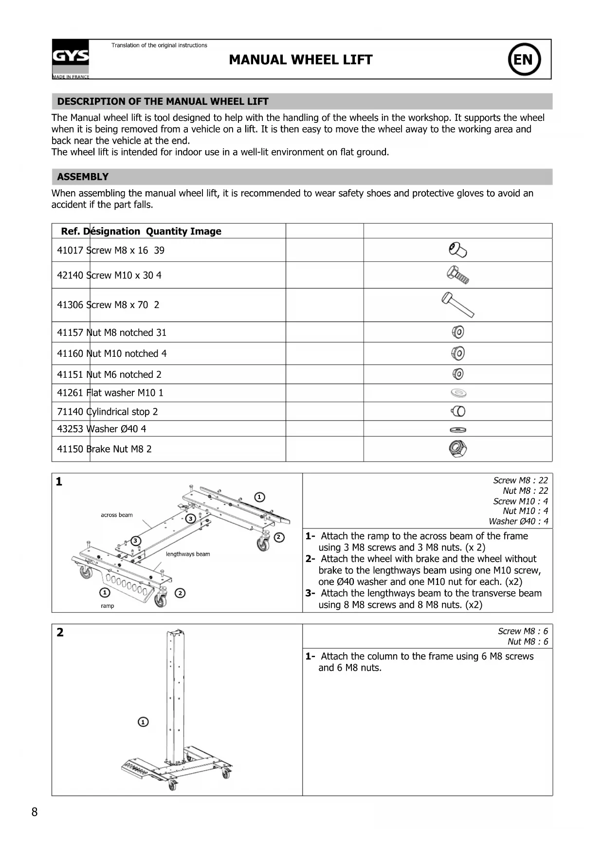
1 across beam lengthways beam ① ② ③ ④ rampScrew M8 : 22
Nut M8 : 22
Screw M10 : 4
Nut M10 : 4
Washer ∅40 : 4
1- Attach the ramp to the across beam of the frame using 3 M8 screws and 3 M8 nuts. (x 2)
2- Attach the wheel with brake and the wheel without brake to the lengthways beam using one M10 screw, one ∅40 washer and one M10 nut for each. (x2)
3- Attach the lengthways beam to the transverse beam using 8 M8 screws and 8 M8 nuts. (x2)
natural_image
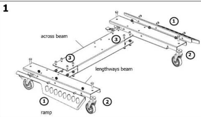
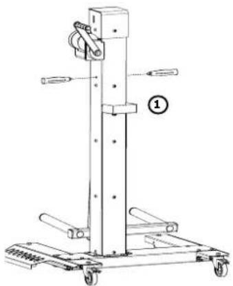
Technical line drawing of a mechanical lift or support structure with a vertical column and wheels (no text or symbols)Screw M8 : 6
Nut M8 : 6
1- Attach the column to the frame using 6 M8 screws and 6 M8 nuts.
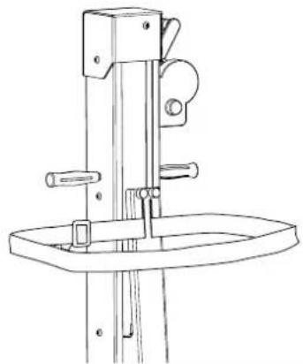
| 3 | Cylindrical stop: 2Screw M8x70: 2Nut M6: 2Nut M8: 2 |
| 1- Secure the cylindrical stops at the top of the carriage with the two M6 nuts.2- Insert the across beam of the trolley into the trolley. Position the largest cable loop between the main beam and the trolley and pass the M8x70 screws through it (make sure the cable passes behind the first axis and then in front of the second). Position the large loop of the cable flat on the base of the vertical beam.3- Insert the M8x70 screws used to fix the two beams. Make sure to pass them through the cable loop (2). Tighten with M8 nuts. |
| 4 | |
| 1- Using a hammer, insert the stop plugs into the tubes on the undrilled side of the tube.2- Insert the roller around the tube. (x2) |
| 5 | Screw M8:2Brake Nut M8:2 |
| 1- Insert the tube with the roller into the cross beam of the carriage, fix it with the M8 screw and the M8 brake nut (x2).2- Insert the stopper with strip into the end of the round tube (x2).3- Insert the stopper with strip at the end of the square tube (x2). |
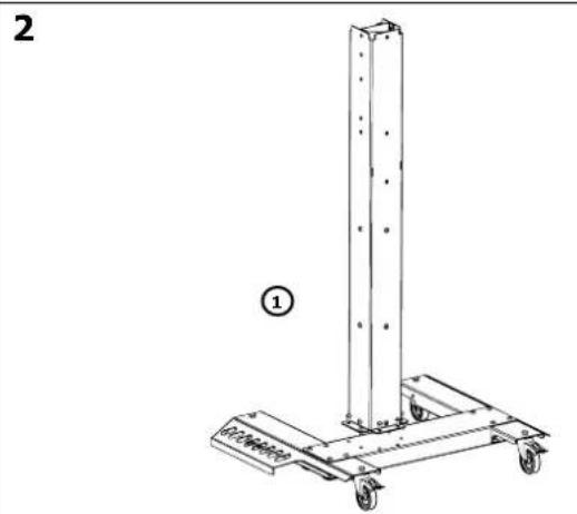
| 6 | 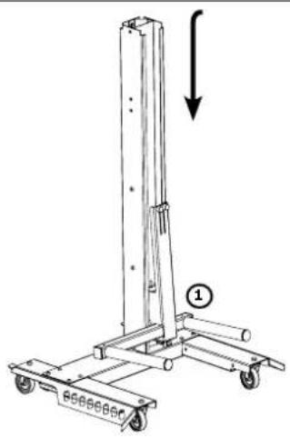 | 1- Position the trolley in the column by inserting it from above. Slide it down to the bottom. | |
7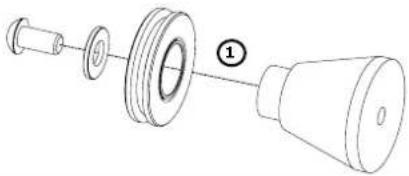 | Screw M8:1Flat washer M10:1 | ||
| 1- Position the pulley on the pulley support, and fix it with an M8 screw and the M10 flat washer. | |||
8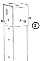 | Screw M8:3 | ||
| 1- Attach the cap to the column with 3 M8 screws | |||
9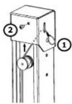 | Screw M8:1 | ||
| 1- Pass the cable around the pulley and bring it out through the light of the cap.2- Secure the pulley bracket with an M8 screw. | |||
10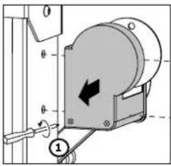 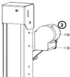 | Screw M8:2 | ||
| 1- Remove the flange (grey plastic part) by unscrewing the 2 screws that hold it to the winch using a cross-head screwdriver.2- Secure the winch to the column using 2 M8 screws.3- Screw the flanges back on. | |||
11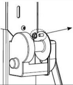 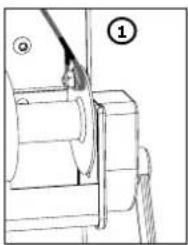 | Screw M8:1Nut M8:1 | ||
| 1- Secure the cable by passing the M8 screw through the cable loop. Tighten with the M8 nut.⚠ Do not use the cable fixing system on the winch composed of a bolt and a plate. Remove it by unscrewing it. | |||
| 12 | Screw M8:1 | ||
| 1- Attach the bolt box to the column with an M8 screw (bend the fixing bracket). | |||
13
natural_image
Technical line drawing of a vertical mechanical lift or support structure with wheels and handle (no text or symbols)1- Screw the handles onto the column.
14
natural_image
Technical line drawing of a mechanical device with no visible text or symbols1- Add the strap
Perform a static loading test: maximum load + safety factor (load x 1.. 5) - (for the test, position the trolley in the middle of the column and place the load centred between the rollers for at least 10 minutes).
DISMANTLING AND RECYCLING
To remove the wheel lift, refer to the «Mounting» section and perform the exact reverse operation.
For recycling, handle the wheel lift to a specialised waste company to ensure the recycling of the different parts.
APPLICATION AND USE
Winch
The wheel lift is equipped with a winch that allows the trolley to go up or down. To mount the trolley, simply turn the crank clockwise. The movement in the opposite direction allows the trolley to be lowered. The winch is equipped with a self-locking brake that allows the trolley with the wheel to be held at a certain height without it going down.

Be careful, giving abnormal blows in the crank handle is likely to unlock the brake.
Strap
The winch wheel lift is equipped with a strap to prevent the wheel from tipping over when moving. Simply pass the looped strap over the wheel and adjust the tightening if necessary.
Brake
The manual winch wheel lift is equipped with individual brakes on each of the two rear wheels. To operate them, press down on the brake of each wheel using your foot.
SAFETY
- The user must use the personal safety equipment in force (safety shoes, gloves, etc.).
- The indicated maximum load must not be exceeded.
- The wheel lift must not be used to lift people.
- The wheel lift must be stored in a place protected from moisture.
- During transport the wheel lift must be packed in such a way that it does not risk tipping over.
Security when travelling
When travelling:
- Lower the trolley to the lowest level to improve stability and safety.
- pay particular attention when passing over doorways, electrical wires or other objects on the ground.
- When using the handle, make sure you are not likely to hit your against something in the way (walls, shelves...).
Loading / unloading and lifting
The user is responsible for loading and unloading.
Engage the rear wheel brakes for the duration of loading / unloading.
The wheel must be positioned on the trolley, as close as possible to the centre column in order to obtain good balance and stability.
Securely strap the wheel to prevent it from tipping over.
For ease of use, position the wheel at the edge of the carriage before unloading.
There is a risk of pinching when the trolley is raised or lowered. Do not place hands or other body parts under the load.
MAINTENANCE
A regular maintenance service must be carried out (once a year) and according to the frequency of use of the wheel lift.
- The maintenance interval is defined according to normal use and with only one daily loading.
- For more intensive use, the maintenance interval should be more frequent.
- Use of spare parts other than those of the manufacturer Gys is not recommended and cannot be carried out without prior agreement.
- Each assembly must be followed by a test loading (see «Assembly» section).
Maintenance procedure
Cleaning
Wash the wheel lift with a product suitable for painted steel surfaces. Follow the instructions on the cleaning product.
Wipe the wheel lift with a cloth after cleaning. Never use a high-pressure cleaner as it can damage the paint.
Wear and tear of parts
Check the condition of the parts to identify any cracks or wear points.
Bolts and screws
Check that the bolts and screws are tightened securely.
Column
Check the condition of the running area of the trolley. Add a suitable grease (bearing grease) to the bearing surfaces.
Wheels
Check that the wheels are working properly.
Grease the bearings.
Ensure the quality of the rubber surfaces.
Brake
Check that the brakes are working properly.
Winch & cable
Check the condition of the cable and its fixing.
Check that the winch and self-locking brake are working properly.
Check that the nut used to stop the crank handle is tightened securely.
It is possible to lubricate with oil when necessary the bushings on the shaft side and to grease the teeth of the gearbox.
Attention, it is strictly forbidden to oil or grease the braking device of the winch located under the crank side housing.
Plate and sticker
Check that the plate and sticker are well glued and visible.
| Label / Sticker Description Location | ||
| Machine plate Label with CE | marking, name and address of the manufacturer, designation, serial number, nominal capacity, year of manufacture | On the cover |
| Safety information Sticker with text containing safety instructions for the operator. On the column | ||
Troubleshooting
The wheel lift is designed for effective and safe use provided that the maintenance instructions are followed. If there are any operating problems, here are some tips:
- If the trolley does not move or with difficulty:
- Check that the cable is secure,
- Check that the cable is correctly positioned in the groove of the pulley.
- If the wheel lift makes an unusual noise:
- Check that the components of the wheel lift are properly mounted, refer to the «Mounting» section,
- Refer to the «Maintenance» section.
If problem carries on, contact your repairer or the manufacturer.
TECHNICAL SPECIFICATIONS
| Features | |
| Model type Manual wheel lift with winch | |
| Maximum Load 40 kg | |
| Cours 1032 mm | |
| Length 615 mm | |
| Width 836 mm | |
| Height 1353 mm | |
| Wheel mini. size | 135/65 R13 |
| Wheel max. size | 300/35 R22 |
| Unloaded weight | 42 kg |
WARRANTY
The warranty covers faulty workmanship for 2 years from the date of purchase (parts and labour).
The warranty does not cover:
- Transit damage.
- Normal wear of parts (eg. : cables, clamps, etc..).
- Damages due to misuse (power supply error, dropping of equipment, disassembling).
- Environment related failures (pollution, rust, dust).
In case of failure, return the unit to your distributor together with:
- The proof of purchase (receipt etc ...)
- A description of the fault reported
natural_image
Technical line drawing of a vertical metal frame with wheels, labeled with number 1 (no text or symbols on the diagram itself)Schraube M8 : 6
text_image
5 ① ② ③ ④ ① ② ③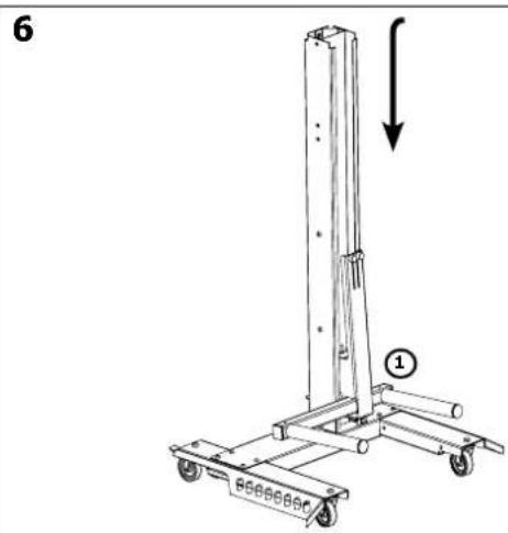
text_image
6 ①text_image
5 ① ② ③ ④ ① ② ③MANUAL WHEEL LIFT - BESCHRIJVING
natural_image
Technical line drawing of a vertical metal frame with wheels, labeled with number 1 (no text or symbols on the diagram itself)Schroef M8 : 6
text_image
Diagram showing two cylindrical objects with labeled parts ① and ②, likely illustrating a physics or engineering concept.text_image
Technical diagram of a vertical lift platform with labeled components and directional arrowDEMONTEREN EN RECYCLEREN
DESCRIZIONE MANUAL WHEEL LIFT
natural_image
Technical line drawing of a mechanical lift or support structure with a vertical column and wheels (no text or symbols)Vite M8 : 6
Dado M8 : 6
text_image
Technical diagram of a vertical lift with numbered components for identification| N° Désignation / Designation / Bezeichnung / Designación / Omschrijving / Denominazione | Ref. | |
| 1 Boîte à boulons / Bolt box / Bolzen-Box / Caja para pernos / Bakje voor bouten / Scatola bulloni | 91223 | |
| 2 Chariot / Trolley / Schlitten / Carro / Hefgedeelte / Carrello 99043 | ||
| 3 Poutre transversale bâti / Across beam frame / Querträgerrahmen / Viga transversal / Dwarsbalk / Trave trasversale telaio | 91193 | |
| 4 Poutre longitudinale bâti / Lengthways beam frame / Längsträgerrahmen / Viga longitudinal / Langsligger / Trave longitudinale telaio | 99038 | |
| 5 Rampe gauche / Left ramp / Linke Auffahrkeile / Rampa izquierda / Zijkant links / Rampa sinistra | 91195 | |
| 6 Rampe droite / Right ramp / Rechte Auffahrkeile / Rampa derecha / Zijkant rechts / Rampa destra | 91194 | |
| 7 Vis M8x16 / M8x16 screw / Schraube M8x16 / Tornillo M8x16 / Schroef M8x16 / Vite M8x16 | 41017 | |
| 8 Écrou M8 / M8 nut / Schraubenmutter M8 / Tuerca M8 / Moer M8 / Dado M8 41157 | ||
| 9 Vis M10x30 / Screw M10x30 / Schraube M10x30 / Tornillo M10x30 / Schroef M10x30 / Vite M10x30 | 42140 | |
| 10 Rondelle ∅40 / Washer ∅40 / Scheibe ∅ 40 / Arandela ∅40 / Sluitring ∅40 / Rondella ∅40 | 41210 | |
| 11 Roue ∅75 hauteur 100 / Wheel ∅75 height 100 / Rad ∅ 75 Höhe 100 / Rueda ∅75 altura 100 / Wieltje ∅75 hoogte 100 / Ruota ∅75 altezza 100 | 71864 | |
| 12 Écrou M10 / Nut M10 / Schraubenmutter M10 / Tuerca M10 / Moer M10 / Dado M10 41160 | ||
| 13 Roue ∅ 75 hauteur 100 avec frein / Wheel ∅ 75 height 100 with brake / Rad ∅ 75 Höhe 100 mit Bremse / Rueda ∅ 75 altura 100 con freno / Wieltje ∅75 hoogte 100 met rem / Ruota ∅ 75 altezza 100 con freno | 71865 | |
| 14 Bouchon à lamelle rond / Round cap with strip / Runde Lamellenstopfen / Tapón a lamina redondo / Afsluitdop / Tappo a lamelle rotondo | 43101 | |
| 15 Tube ∅ 30 / Tube ∅ 30 / Rohr ∅ 30 / Tubo ∅ 30 / Stang ∅ 30 / Tubo ∅ 30 91279 | ||
| 16 Tube PVC / Tube PVC / PVC-Rohr / Tubo PVC / PVC buis / Tubo PVC 91072 | ||
| 17 Bouchon de butée / Stop cap / Verschlussstopfen / Tapón de tope / Dopje / Tappo di battuta | 90184 | |
| 18 Ecrou frein M8 / Brake nut M8 / Sicherungsschraubenmutter M8 / Tuerca freno M8 / Borgmoer M8 / Dado freno M8 | 41150 | |
| 19 Bouchon tube carré / Square tube cap / Vierkantrohrkappe / Tapón de tubo cuadrado / Vierkante afsluitdop / Tappo tubo quadrato | 43250 | |
| 20 Chariot poutre transverale / Across beam trolley / Querbalkenschlitten / Carro viga transversal / Dwarsbalk hefgedeelte / Carrello trave trasversale | 91039 | |
| 21 Vis M8x70 / Screw M8x70 / Schraube M8x70 / Tornillo M8x70 / Schroef M8x70 / Vite M8x70 | 41306 | |
| 22 Coiffe colonne / Column cover / Säulenständerschutzkappe / Capuchón columna / Kap bovenop de kolom / Terminale colonna | 91222 | |
| 23 Rondelle plate M10 / Flat washer M10 / Maulscheibe M10 / Arandela llana M10 / Platte sluitring M10 / Rondella piatta M10 | 43207 | |
| 24 Poulie / Pulley / Scheibe / Polea / Katrol / Puleggia 90178 | ||
| 25 Support poulie / Pulley support / Scheibenauflager / Soporte polea / Houder katrol / Supporto puleggia | 90188 | |
| 26 Treuil / Winch / Winde / Torno / Lier / Verriccello 70523 | ||
| 27 Poignée / Handle / Griff für Spotter-Klemme / Manija / Handvat / Impugnatura | 72069 | |
| 28 Ecrou M6 / Nut M6 / Schraubenmutter M6 / Tuerca M6 / Moer M6 / Dado M6 41151 | ||
| 29 Pied butée cylindrique en caoutchouc / Cylindrical rubber stop foot / Zylindrischer Gummi-Verschlussfuß / Pie de tope cilíndrico en caucho / Cilindervormige rubberen stopper / Tappo cilíndrico in gomma | 71140 | |
| 30 Colonne / Column / Säulenständer / Columna / Kolom / Colonna / Scatola bulloni - | ||
PICTOGRAMMES / PICTOGRAMS / PIKTOGRAMME / PICTOGRAMAS / PICTOGRAMMEN / PITTOGRAMMI
 | - Attention ! Lire le manuel d'instruction avant utilisation.- Caution ! Read the user manual.- Achtung! Lesen Sie die Betriebsanleitung.- iCuidado! Lea el manual de instrucciones antes de su uso.- Внимание! Прочтите инструкцию перед использованием.- Let op! Lees aandachtig de handleiding.- Attenzione ! Leggere il manuale utente. |
 | - Matériel conforme aux Directives européennes. La déclaration UE de conformité est disponible sur notre site (voir à la page de couverture).- Device complies with europeans directives, The EU declaration of conformity is available on our website (see cover page).- Gerät entspricht europäischen Richtlinien. Die Konformitätserklärung finden Sie auf unsere Webseite.- Aparato conforme a las directivas europeas. La declaración de conformidad UE está disponible en nuestra página web (dirección en la portada).- Устройство соответствует директивам Евросоюза. Декларация о соответствии доступна для просмотра на нашем сайте (ссылка на обложке).- Apparaat in overeenstemming met de Europese richtlijnen. De verklaring van overeenstemming is te downloaden op onze website (adres vermeld op de omslag).- Materiale in conformità alle Direttive europee. La dichiarazione di conformità è disponibile sul nostro sito (vedere sulla copertina). |
 | - Produit dont le fabricant participe à la valorisation des emballages en cotisant à un système global de tri, collecte sélective et recyclage des déchets d'emballages ménagers.- The product's manufacturer contributes to the recycling of its packaging by contributing to a global recycling system.- Produkt für getrenne Entsorgung (Elektroschrott). Werfen Sie es daher nicht in den Hausmüll!- Producto sobre el cual el fabricante participa mediante una valorización de los embalajes cotizando a un sistema global de separación, recogida selectiva y reciclado de los deshechos de embalajes domésticos.- Аппарат, производитель которого участвует в глобальной программе переработки упаковки, выборочной утилизации и переработке бытовых отходов.- De fabrikant van dit product neemt deel aan het hergebruik en recyclen van de verpakking, door middel van een contributie aan een globaal sorteer en recycle-systeem van huishoudelijk verpakkingsafval.- Prodotto con cui il fabbricante partecipa alla valorizzazione degli imballaggi in collaborazione con un sistema globale di smistamento, raccolta differenziata e riciclaggio degli scarti d'imballaggio. |
 | - Produit recyclable qui relève d'une consigne de tri.- This product should be recycled appropriately.- Recyclingprodukt, das gesondert entsorgt werden muss.- Producto reciclable que requiere una separación determinada.- Этот аппарат подлежит утилизации.- Product recyclebaar, niet bij het huishoudelijk afval gooien.- Prodotto riciclabile soggetto a raccolta differenziata. |