Gyspot Combi Arcpull - Generator GYS - Free user manual and instructions
Find the device manual for free Gyspot Combi Arcpull GYS in PDF.
User questions about Gyspot Combi Arcpull GYS
0 question about this device. Answer the ones you know or ask your own.
Ask a new question about this device
Download the instructions for your Generator in PDF format for free! Find your manual Gyspot Combi Arcpull - GYS and take your electronic device back in hand. On this page are published all the documents necessary for the use of your device. Gyspot Combi Arcpull by GYS.
USER MANUAL Gyspot Combi Arcpull GYS
INSTALLATION - FONCTIONNEMENT DU PRODUIT
DESCRIPTION DU MATÉRIEL (FIG-1)
INTERFACE HOMME MACHINE ALU (IHM) (FIG-II)
1-Bouton Menu/Valider
5-Bouton D+
2-Bouton Retour
6-Bouton D
3-Bouton G+
7-Ecran
4-Bouton G-
INTERFACE HOMME MACHINE ACIER (IHM) (FIG-II)
1- Afficheur outfits
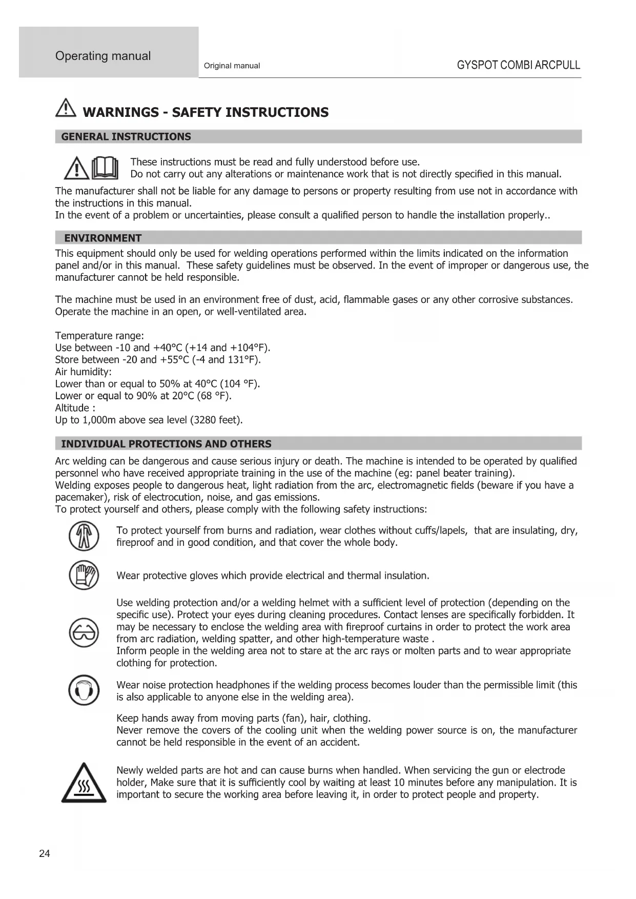
WARNING - SAFETY INSTRUCTIONS
GENERAL INSTRUCTIONS

These instructions must be read and fully understood before use.
Do not carry out any alterations or maintenance work that is not directly specified in this manual.
The manufacturer shall not be liable for any damage to persons or property resulting from use not in accordance with the instructions in this manual.
In the event of a problem or uncertainties, please consult a qualified person to handle the installation properly..
ENVIRONMENT
This equipment should only be used for welding operations performed within the limits indicated on the information panel and/or in this manual. These safety guidelines must be observed. In the event of improper or dangerous use, the manufacturer cannot be held responsible.
The machine must be used in an environment free of dust, acid, flammable gases or any other corrosive substances. Operate the machine in an open, or well-ventilated area.
Temperature range:
Use between -10 and +40^ (+14 and +104°F).
Store between -20 and +55^ (-4 and 131^
Air humidity:
Lower than or equal to 50% at 40^ (104 F ).
Lower or equal to 90% at 20^ (68 °F).
Altitude :
Up to 1,000m above sea level (3280 feet).
INDIVIDUAL PROTECTIONS AND OTHERS
Arc welding can be dangerous and cause serious injury or death. The machine is intended to be operated by qualified personnel who have received appropriate training in the use of the machine (eg: panel beater training).
Welding exposes people to dangerous heat, light radiation from the arc, electromagnetic fields (beware if you have a pacemaker), risk of electrocution, noise, and gas emissions.
To protect yourself and others, please comply with the following safety instructions:

To protect yourself from burns and radiation, wear clothes without cuffs/lapels, that are insulating, dry, fireproof and in good condition, and that cover the whole body.

Wear protective gloves which provide electrical and thermal insulation.

Use welding protection and/or a welding helmet with a sufficient level of protection (depending on the specific use). Protect your eyes during cleaning procedures. Contact lenses are specifically forbidden. It may be necessary to enclose the welding area with fireproof curtains in order to protect the work area from arc radiation, welding spatter, and other high-temperature waste.
Inform people in the welding area not to stare at the arc rays or molten parts and to wear appropriate clothing for protection.

Wear noise protection headphones if the welding process becomes louder than the permissible limit (this is also applicable to anyone else in the welding area).
Keep hands away from moving parts (fan), hair, clothing.
Never remove the covers of the cooling unit when the welding power source is on, the manufacturer cannot be held responsible in the event of an accident.
Newly welded parts are hot and can cause burns when handled. When servicing the gun or electrode holder, Make sure that it is sufficiently cool by waiting at least 10 minutes before any manipulation. It is important to secure the working area before leaving it, in order to protect people and property.
WELDING FUMES AND GAS

Fumes, gases and dusts emitted by welding are harmful to health. It is mandatory to ensure adequate ventilation, and an additional air supply may be required. An air-fed mask could be a solution in situations where there is inadequate ventilation.
Check the extraction system's performance against the relevant safety standards.
Caution : Welding in confined spaces requires safety monitoring from a safe distance. In addition, the welding of certain materials containing lead, cadmium, zinc, mercury or beryllium can be very harmful. also remove any grease on the workpieces before welding.
Cylinders should be stored in open or well-ventilated areas. They should be stored in an upright position and kept on a stand or trolley.
Welding should not be carried out near grease or paint.
FIRE AND EXPLOSION HAZARDS
Fully protect the welding area, and ensure that flammable materials are kept at least 11 metres away. Fire fighting equipment should be kept close to wherever the welding activities are being undertaken.
Be careful of spatter and sparks, even through cracks, as it can be the source of a fire or an explosion.
Keep people, flammable objects and pressurised containers at a safe distance.
Welding in closed containers or tubes is to be avoided. If the containers or tubes are open, they must be emptied of all flammable or explosive materials (oil, fuel, residual gas...).
Grinding work must not be directed towards the source of the welding current or towards any flammable materials.
GAS CYLINDERS

Gas escaping from cylinders can cause suffocation if there is too high a concentration of it in the welding area (ensure good ventilation).
The machine must be transported in complete safety: gas cylinders must be closed and the welding power source turned off. They should be stored upright and supported to limit the risk of falling.
Close the cylinder between uses. Beware of temperature variations and exposure to the sun.
The cylinder must not come into contact with a flame, an electric arc, the gun, a ground clamp, or any other source of heat or potential ignition.
Be sure to keep it away from electrical and welding circuits. Never weld a pressurised cylinder.
Be careful when opening the cylinder valve, keep your head away from the tap and ensure that the gas used is suitable for the welding application.
ELECTRICAL SAFETY

The electrical network used must be earthed. Use the recommended fuse size from the rating plate. A direct or indirect electric shock can cause a serious injury, or even death.
Do not touch any live part of the machine (inside or outside) when it is plugged in. (Guns, clamps, cables, electrodest because it is connected to the welding circuit.
Before opening the welding power source, disconnect it from the mains supply and wait 2 minutes. So that all the capacitors are discharged.
Do not touch the gun or the electrode holder and the earth clamp at the same time.
Ensure that the cables are changed, if they are damaged, by qualified and authorised personnel. Measure the cable cross-section according to the intended application. Always use dry and in-fact clothing to insulate yourself from the welding circuit. Wear insulated shoes in all working environments.
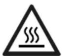
Warning! Very hot surface. Risk of burns.
- The parts and pieces that have just been heated are hot and may cause burns when manipulated.
- Do not touch any hot parts with your hands.
- Wait for parts and equipment to cool before handling them.
- In the event of a burn, rinse with plenty of water and seek medical attention immediately.
EMC CLASSIFICATION

This Class A device is not intended for use in a residential environment where power is provided by the public low-voltage local supply network. There may be potential difficulties in maintaining electromagnetic compatibility at these sites, due to both conducted, and radiated radio frequency interference.
Steel:
This equipment does not comply with IEC 61000-3-12 and is designed to be plugged into private, low voltage, power supply networks. It is intended to be connected to the public mains supply only at medium or high voltage level. If it is connected to a public low voltage supply network, it is the responsibility of the installer or user of the product to make sure, by consulting the distribution network operator, that the unit can be connected.
Aluminium:
Provided that the impedance of the low-voltage public electrical network at the common interconnection point is less than Z = 0.45 Ohms, this equipment complies with IEC 61000-3-11 and can be connected to public low-voltage electrical mains. It is the responsibility of the installer or operator of the product to ensure this, in consultation with the distribution network operator if necessary, that the network impedance complies with the impedance restrictions.
Steel / Aluminium:
This equipment complies with IEC 61000-3-11.
EN 61000-3-11 Steel:
This equipment complies with IEC 61000-3-11 if the impedance of the power supply, at the point of connection to the electrical installation, is less than the maximum permissible power supply impedance Z_max = 0.130 Ohms.
EN 61000-3-12 Aluminium:
This equipment complies with the IEC 61000-3-12 standard.
ELECTROMAGNETIC EMISSIONS
An electric current passing through any conductor produces localised electric and magnetic fields (EMF). The welding current produces an electromagnetic field around the welding circuit and the welding equipment.
Electromagnetic fields (EMFs) can interfere with some medical devices, pacemakers for example. Protective measures must be taken for people with medical implants. For example, restricted access for spectators, or an individual risk assessment for welders.
All welders should use the following guidelines to minimise exposure to the welding circuit's electromagnetic fields:
- position the welding cables together - secure them with a clip, if possible;
- position yourself (head and body) as far away from the welding circuit as possible;
- never wrap the welding cables around your body;
- do not position yourself between the welding cables. Place both welding cables on the same side of the body;
- connect the return cable to the workpiece as close as possible to the area that will be welded;
- do not work directly next to the welding power source, Do not sit on it or lean against it;
- do not transport the welding power source or wire feeder while welding.

Pacemaker users should consult a doctor before using this equipment.
Exposure to electromagnetic fields during welding may have other health effects that are not yet known.
RECOMMENDATIONS TO ASSESS THE WELDING AREA AND WELDING INSTALLATION
General Information
It is the user's responsibility to install and use the arc welding equipment according to the manufacturer's instructions. If electromagnetic interference is detected, it is the user's responsibility to resolve the situation using the manufacturer's technical support. In some cases, this corrective action may be as simple as earthing the welding circuit. In other cases, it may be necessary to electromagnetically shield the welding power source and the workpiece as a whole by installing input filters. In all cases, electromagnetic interference should be reduced until it is no longer a concern.
Assessing the welding area
Before installing arc welding equipment, the user should assess the potential electromagnetic problems in the surrounding area. The following should be taken into account:
a) the presence above, below and next to the arc welding equipment of other power cables, control cables, signal or telephone cables;
b) radio and television receivers and transmitters;
c) computers and other control equipment,
d) critical safety equipment, for example, industrial equipment protection;
e) the well-being of nearby persons, for example, those using pacemakers or hearing aids,
f) the equipment used for calibrating or measuring;
g) the protection of other surrounding equipment.
The operator has to ensure that the devices and equipment used in the same area are compatible with each other. This may require further protective measures;
h) the time of day when welding or other operations are to be carried out.
The size of the surrounding area to be taken into account will depend on the building's structure and the other activities taking place there. The surrounding area may extend beyond the boundaries of the premises.
Assessment of the welding equipment
In addition to assessing the area, the arc welding equipment's assessment can be used to identify and resolve cases of interference. The assessment of emissions must include in situ measurements as specified in Article 10 of CISPR 11. In situ measurements can also be used to confirm the effectiveness of mitigation measures.
RECOMMENDATION ON METHODS OF ELECTROMAGNETIC EMISSIONS REDUCTION
a. The mains power grid: Arc welding equipment should be connected to the mains power grid according to the manufacturer's recommendations. If interference occurs, it may be necessary to take additional precautionary measures such as filtering the mains power supply. Consider protecting the power cables of permanently installed arc welding equipment within a metal pipe or a similar casing. The power cable should be protected along its entire length. The shield should be connected to the welding power source to ensure that there is good electrical contact between the conduit and the welding power source enclosure.
b. The maintenance of arc welding equipment: Arc welding equipment should be subject to routine maintenance as recommended by the manufacturer. All access points, covers and service openings should be closed and properly locked when the arc welding equipment is in use. The arc welding equipment should not be modified in any way, except for those changes and adjustments mentioned in the manufacturer's instructions. It is advisable, in general, the arc ignition and stabilization parts should be adjusted and maintained according to the manufacturer's recommendations.
c. Welding cables: Cables should be as short as possible, placed close together either near or on the ground.
d. Equipotential bonding: Consideration should be given to linking all metal objects in the surrounding area. However, metal objects connected to the workpiece increase the risk of an electric shock to the operator if they touch both the metal objects and the gun shaft. It is necessary to insulate the operator from such metal objects.
e. Earthing the workpiece: In cases where the part to be welded is unearthed for electrical safety reasons or due to its size and location, which is the case, for example, the hull of a ship or steel frameworks of buildings, an earthed connection can in some cases but not always, reduce emissions. Care should be taken to avoid the earthing of parts which could increase the risk of injury to users or damage to other electrical equipment. If necessary, the connection of the workpiece to earth should be made directly, but in some countries; rules may not allow such a direct connection, he connection should be made with a suitable capacitor chosen according to national regulations.
f. Protection and shielding: The selective protection and encasing of other cables and equipment in the surrounding area may limit interference problems. The safeguarding of the entire welding area may be considered for special applications.
THE TRANSPORTING AND MOVING OF THE MACHINE'S POWER SOURCE

The machine is equipped with a handle to easy transportation. Be careful not to underestimate its weight. The handle cannot be used to hang or attach the machine on something else.
Do not use the cables or gun to move the welding power source. It should be moved in an upright position.
Do not carry or transport the power source overhead of people or objects.
Never lift the machine while there is a gas cylinder on the support shelf. Their transportation requirements are different.
SETTING UP THE EQUIPMENT
- Place the welding power source on a floor with a maximum inclination of 10^ .
- Provide sufficient space to ventilate the welding power source and access the controls.
- Do not use in an area with conductive metal dust.
- Power cables, extension cables and welding cables should be fully unwound to avoid overheating.
- The manufacturer assumes no responsibility for damage to persons or objects caused by improper and dangerous use of this equipment.
- The welding power source should be protected from heavy rain and not exposed to direct sunlight.
- The equipment has an IP21 protection rating, meaning:
- the dangerous parts of the machine are protected against entry by objects greater than 12.5mm and,
- Protection against vertically falling drops of water
- Power cables, extension cables and welding cables should be fully unwound to avoid overheating.

The manufacturer assumes no responsibility for damage to persons or objects caused by improper and dangerous use of this equipment.
MAINTENANCE/RECOMMENDATIONS


- Anyone using this machine needs to have received appropriate training in the use of the device, in order to get the most out of its performance, and to carry out the work in accordance with the instructions (e.g: panel beater training).
- Check which welding process is authorised by the manufacturer before attempting any vehicle repair.
- The maintenance and the repair of the . Any work undertaken by a third party on the machine will invalidate the warranty. The manufacturer will not accept liability in the event of an incident that would occur after this work was undertaken.
- Switch off the power supply by pulling out the plug, and wait two minutes before working on the equipment. Inside, the voltages and currents are high and dangerous.
- All the welding tools will wear off with use. Ensure that these tools are clean to get the best results.
- Before using the gun, check the condition of the different components (star, single-point electrode, carbon electrode, ...) and then clean or replace them if they are in poor condition.
- On a regular basis, remove the cover and blow out any dust. Take advantage of the opportunity to have the electrical connections checked with an insulated tool by a qualified professional.
- Regularly review the condition of the power cable and welding connection cables. If there are signs of damage, they should be replaced by the manufacturer, its customer service department, or a similarly qualified person, to avoid any danger.
- Leave the welding power source vents free for air intake and outflow.
INSTALLATION - PRODUCT OPERATION
EQUIPMENT DESCRIPTION (FIG-1)
Next generation 2-in-1 dent puller. The Gyspot Combi ARCPULL is used to remove dents from steel and aluminium bodies. This method of repair by pulling without disassembly is both time-saving and cost-effective.
This machine combines 2 different dent-pullers, with 2 different control panels:
| A steel dent remover An aluminium dent remover | |
| with power source, manual gun and ground cable - The trigger gun is plugged into connector no. 6 and the control cable into connector no. 5 - The triggerless gun (optional) plugs into connector no. 7 - The ground cable is fixed in position no. 4 | WITH DRAWN ARC WELDING, the linear motor gun with integrated quick ground (2 flexible studs) - The gun is plugged into connector no. 8 and no. 9 - The gun control cable plugs into connector no. 10 - The gas hose connects to no. 13 |
Power source GYSPOT COMBI ARCPULL (FIG-I)
1-Alu Keypad
2-Switch (On/Off/On)
3- Steel Keypad
4- Ground cable Steel
5- Gun trigger connector Steel
6-Texas/dinse for gun with trigger Steel
7-Texas/dinse for triggerless gun Steel
8-Texas/dinse for Alu gun cable (-)
9-Texas/dinse for Alu gun cable (+)
10- Sub-base for Alu gun control cable connector
11-Gas outlet for gun cable (Alu)
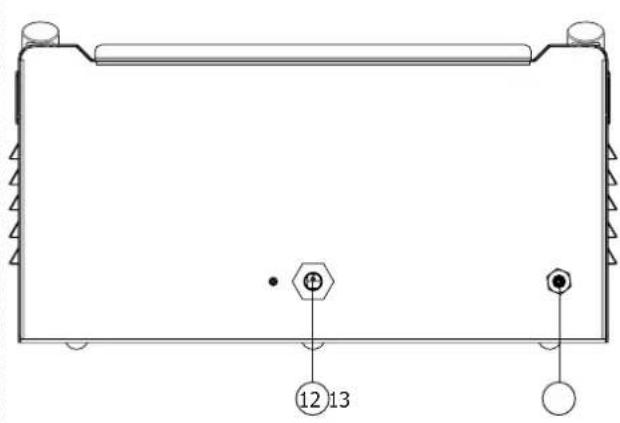
12- Mains cable
13-Gas inlet connected to the cylinder (15 l/min) (G1/4 D6)
14- USB connector for Alu software updates
Automatic gun GYSPOT ARCPULL 200 - Aluminium function (FIG-I)
1- Trigger
2-Locking ring for electrode holder
3-Locking knob for rods
4- Connector for gun control cable
5- Positive Texas/dinse
6-Negative Texas/dinse
7-Gas inlet
8- On LED (green)
9- Contact LED (blue)
10-Fault LED (red)
ALU HUMAN-MACHINE INTERFACE (HMI) (FIG-II)
1- Menu/Enter button
2-Back/return button
3-G+ button
4-G- button
5- D+ button
6-D- button
7- Screen/display
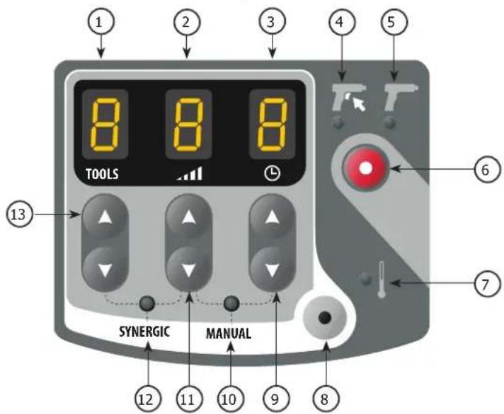
STEEL HUMAN-MACHINE INTERFACE (HMI) (FIG-II)
1- Tool display
2- Power level display
3-Spot time display
4- Manual ignititon indicator light
5- Automatic ignition indicator light
6- Ignition type selection button
7- Thermal fault indicator light
8- Mode selection button (Manual/Synergic)
9-Spot-weld time selection buttons (+ / - )
10- MANUAL mode indicator light
11- Power level selection buttons (+/-)
12-SYNERGIC mode indicator light
13- Tool selection buttons (+/-)
POWER SUPPLY AND START-UP
- This product is supplied with a 16 A CEE7/7 plug and must be connected to an electric installation which is three-wire single-phase 230V (50-60Hz) with an earthed neutral. Check that the power supply and its protection (fuse and/or circuit breaker) are compatible with the current required to run the machine. This equipment is designed to operate on an electrical installation equipped with a 16A curve C, D or K circuit breaker. The effective absorbed current (I1eff) for aluminium and the permanent absorbed current (I1p or ILp) for steel is shown on the device for the maximum operating settings.
Aluminium function
The left-hand side of the product is the drawn-arc function, it is used for welding inserts: primarily pull rings on aluminium based materials, but also studs and insulation nails on aluminium or steel based materials. It has a Synergic mode and a Manual mode.
- To switch the unit on, turn the on/off switch in the centre of the product to the left "I".
- The device will enter protection mode if the power supply voltage is over 265 V AC. (If this is the case, the machine displays POWER DEFAULT). Normal functioning will resume once the power supply is under 265V.
- When it starts up, the product always runs in synergic mode. Changing the mode (Manual or Synergic) is done via the Main Menu.
Delivered with the following aluminium accessories:
GAS PROTECTION
Depending on the material to be welded, gas protection may be necessary.
The gas flow must be set between 12L/min and 15L/min.
The following table lists the gases required depending on the inserts to be welded and their material. This table is given as an indication, pre-weld tests are recommended.
| Insert to be welded Gas No gas Usage | |||
| Alu pulling ring Argon Not recommended | |||
| Stud, aluminium insulation nail | ArHe 30% Not recommended | ||
| Steel pulling ring ArCO2 8% Possible | |||
| Stud, steel insulation nail, etc. | ArCO2 8% Possible | ||
Note :
In the case of welding aluminium, pure Argon (Ar) can be used instead of the 30% Argon-Helium mixture (ArHe30%) . Also, in the case of steel (Fe or FeCu) welding, it is possible to use pure Argon (Ar) instead of 8% Argon- CO^2 mixture (ArCO^2 8%) . In both cases, the settings pre-set by the Synergy are no longer guaranteed, and it may be necessary to switch to Manual Mode.

Do not set the torque over 5N.m when tightening the gas input coupling.
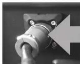
CONNECTING THE GUN TO THE POWER SOURCE

The connection and disconnection of the gun control connector to the power source socket must only be done with the power source switched off.

The ring of the gun control connector must always be properly screwed to the power source socket before starting the product.
PROCESS FOR WELDING AN INSERT WITH DRAWN ARC
| Phase | Ignition | Penetration and cleaning | Arc Binding | |
| T (ms) | 0 to 200 ms 10 to 500 ms 0 | to 50 ms | ||
| I (A) | ≈80-150 A | 50 to 60 A | 50 à 200 A* | ≈80-150 A |
Ignition: the insert (pull ring studs, etc.) is placed in contact with the supporting material. Pressing the trigger starts the welding process: the power source sends current to the stud, the gun shaft rises slightly, A low-intensity electric arc is then created.
Penetration and cleaning: This phase could also be called preheating. The power source regulates a current to ensure a low-intensity arc, the heat generated by this arc allows:
-
burning off impurities from the backing sheet (grease, oil, electrolytic zinc coating).
-
to preheat the two pieces, and thus limiting the thermal impact of the welding arc, to improve the quality of the weld. During this phase neither the insert, or the support plate, is melted. Also, this phase does not allow the zinc layer of a galvanised plate to be removed.
The arc: the power source significantly increases the current to create a high-energy arc that creates a molten pool on the support plate and causes the end of the insert to melt.
The binding: The gun plunges the insert into the molten weld pool.
Note : In the case of steel, the thickness of the supporting sheet must not be less than 1/4 of the diameter of the insert, and 1/2 of the diameter in the case of aluminium.
DRAWN ARC WELDING
- Mount the ring holder
- Strip off all paint from the area where the weld is to be executed.
- Select the correct synergy to suit the welding of the ring.
- Connect the negative texas plug from the gun to the unit (no earth clamp is used).
- In the case of manual operation; set the digital "Flex" spring to OFF
- Insert a ring into the ring holder.
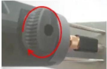
- Unlock the ground rods with the knob.
- Position the gun on the workpiece and bring the ring into contact with it. As soon as the gun makes a "beep" or that the LED contact (blue) is switched on, lock the ground rods with the knob.
- Press the trigger
- Once the weld is complete, unlock the knob to release the pins and lift the gun to disengage the ring.
Check the polarity of the gun's texas/dinse:
| Insert to be welded | Positive cable connection (red mark) | Negative dinse cable Usage | |
| Alu pulling ring Negative dinse connector (-) Positive dinse connector (+) Recommended | |||
| Stud, aluminium insulation nail | Positive dinse connector (+) | Negative dinse connector (-) | Recommended |
| Steel pulling ring Positive dinse connector (+) Negative dinse connector (-) Possible | |||
| Stud, steel insulation nail, etc Positive dinse connector (+) Negative dinse connector (-) Possible | |||
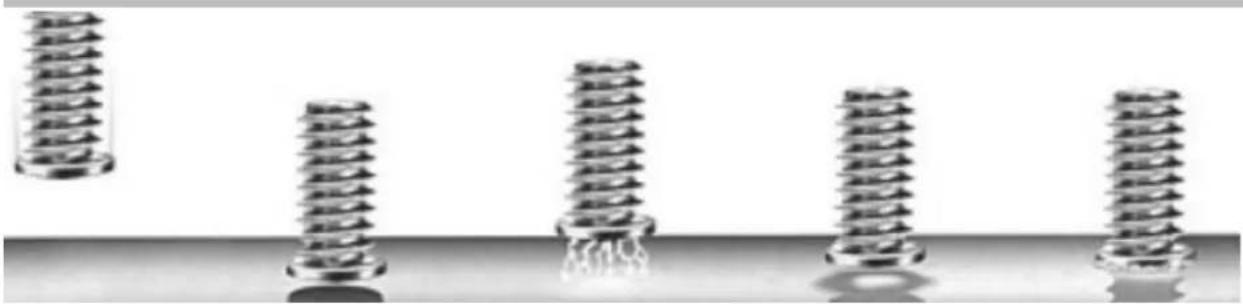
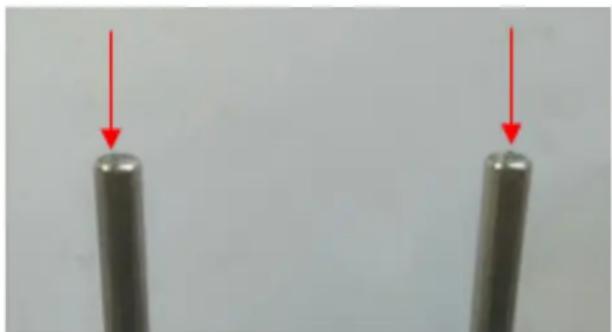
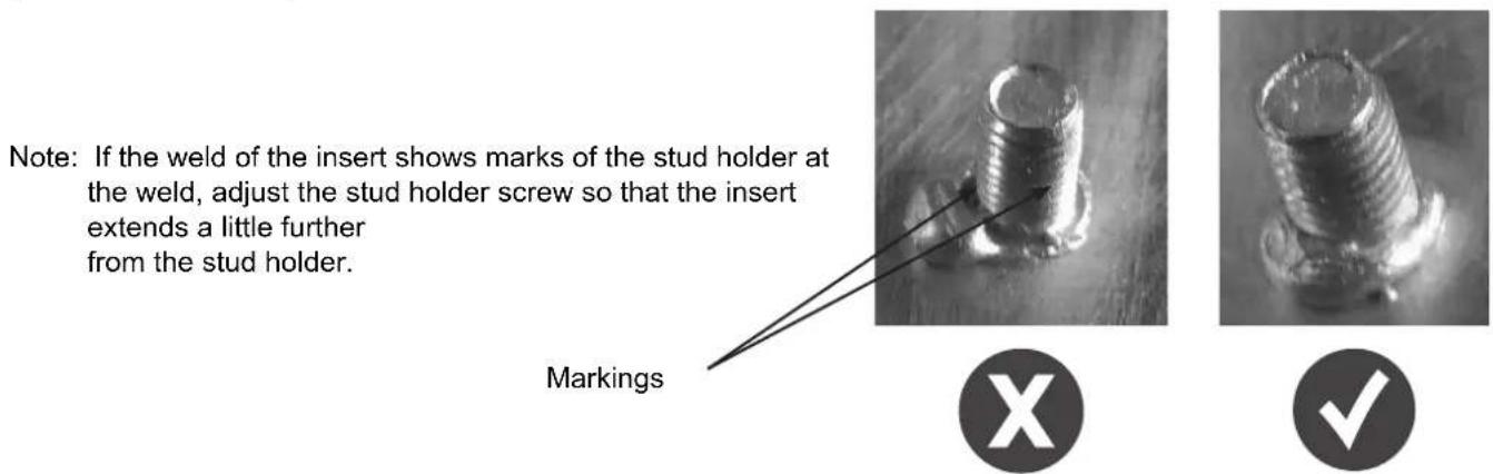
Every 30 pull ring welds, the message "Check stems" appears on the display. Check the end of the ground rods If they show signs of
welding, lightly sand them with abrasive paper to restore their electrical contact.
Press to confirm and reset the counter.
WELDING IN MANUAL MODE
In Synergic Mode the height of the arc, the time and current for the different phases are selected automatically by the machine. A synergy is therefore determined by the type of part to be welded, its material, its gas protection, its size, and the supporting plate.
The gas type to be used is shown on the display. In case of incorrect polarity on the gun, a message appears on the display and the fault LED (red), on the gun, flashes.

The different welding parameters are defined for the attachments that GYS sell.
These synergies remain applicable for inserts up to 35mm as long as they are of the same type and material as those sold by GYS (according to ISO 13918).
The synergies of aluminium inserts (excluding pull rings), were established on support plates that had been preheated to a temperature of 50 - 60^ .
It is advisable to carry out a few test welds on a suitable support plate beforehand, to ensure that the weld will hold.
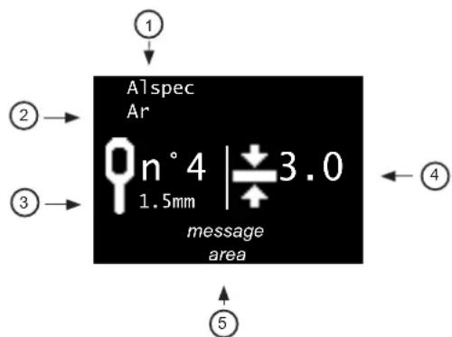
On the main Mode screen, Synergies are displayed:
1 The material of the insert: AlMg, Fe, FeCu, etc.
2 - The type of weld pool protection: No Gas, the type of gas recommended
3 The pictogram of the part to be welded
4 — The thickness of the sheet metal to which the part will be welded
5—A message field specifying the status of the product
From the synergy displayed on the screen, defined by a part type (3), its material (1) and its protection (2), it is only possible to change the size of the part (M4, M5, etc.) by pressing G+ and G- without having to go through the settings menu.
| Insert Pictograms | Comments Photo | ||
| Pull ring | n°41.5mm | Pressing the G+ and G- keys will scroll through all the ring synergies contained in the unit. The material (1) and gas protection (2) are updated automatically. | 00 |
| Stud | M6 | Synergies associated with studs | |
| Insulation nail | ∅2 |
THICKNESS OF THE SUPPORT PLATE
Thickness displayed in millimetres.
To increase or decrease the thickness of the sheet on which the insert will be welded, press the D+ and D- keys. The thickness ranges that can be selected are dependent on the type, size, and material of the part to be welded.
If the thickness of the sheet metal is less than that shown on the display, the sheet may become deformed at the weld. When the display shows 12 sheet thickness is sufficient and the welding parameters of the synergy are no longer affected.
If this symbol does not appear, then the maximum sheet metal thickness has been reached. Over this thickness, the welding of the insert is no longer guaranteed.
Note : When switching from Synergic to Manual mode, all welding parameters (current, time, height, etc.) associated with that synergy are transferred to manual mode. This makes it possible to fine-tune the machine settings if the selected synergy does not achieve the expected result (welding with too much, or not enough, energy).
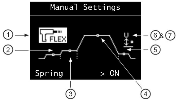
WELDING IN MANUAL MODE
In Manual Mode the time, current, the lift height for the insert and the activation of the digital spring are user-defined.
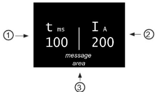
The main screen of Manual Mode displays:
1—Arc time in milliseconds
2—Arc current
3—A message field specifying the status of the product
LIST OF MESSAGES SHOWN AT THE BOTTOM OF THE WELDING DISPLAY
| Message Description | |
| Gun disconnected No gun is connected to the unit. | |
| Texas disconnected The positive texas/dinse of the gun is | not connected to the power source. |
| Texas inverted (Synergic mode only) The polarity of the texas/dinse connectors is reversed in relation to the polarity required by the selected synergy. | |
| Ready The rest period is complete the unit is now available to weld. | |
| Movement only A trigger pull was detected without an insert | being brought into contact with the support plate. The gun then does a mechanical movement only, the power source is not switched on. |
| Contact The product detects that an insert is in contact with the support plate. If welding is done with gas shielding, the solenoid valve opens for pre-gas. | |
| Welding Welding cycle in progress | |
| Welding completed The welding cycle is complete | |
| Pre-Gas Displayed when a trigger pull is detected before the pre-gas time has elapsed (see section 7.4.3). For the welding to take place, it is necessary to remain in the right position (insert is always in contact with the support sheet), and wait for the end of the pre-gas. | |
| Lost contact Displayed when contact between the insert and the sup- port sheet is lost before the pre-gas time has elapsed. | |
| Arc breakage | An arc break occurred during the welding cycle. Checking the weld will be necessary. |
| Lift gun Displayed at the end of the welding cycle, if the gun | is still in position on the insert. |
MAIN MENU
To access the Main Menu from Synergic and Manual modes, press the Menu/Enter button Press the + and G- keys to move the section cursor. Make the selection by pressing the Menu/Validate button.
Main Menu
Settings Manual Mode Configuration
- "Settings" accesses the welding parameters (synergic or manual).
- "Manual Mode"/" Synergic Mode" changes the welding method of the machine
- "Configuration" accesses the advanced configuration of the machine (language, gas management, information, etc.).
Press the back button to return to the welding screen.
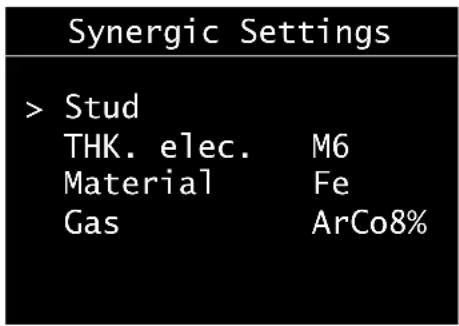
SYNERGIC MODE SETTINGS MENU
When operating in synergic mode, the setting menu is used for selecting the type of insert to be welded, its size, its material and type of gas shielding.
In Synergic Mode, the settings are selected in order from top to bottom:
1 - Type of insert : studs, pins, rings.
2 Size of the insert "EP.elec":Mx, x ,etc.
3Material of the insert: Fe, FeCu, Al, etc.
4 - Type of welding protection: Ferrule, No gas, or with Gas
Note : When welding is to be done with gas shielding, the gas that is displayed is the one recommended to guarantee the weld strength. In the event that this gas is not available, it may be necessary to switch to Manual Mode.
Press the G+ and G- keys to move the left cursor, and press the D+ and D- keys to change the values of each item.
Push the Menu/Enter button to confirm the synergy settings and return to the synergic welding screen.
Press the return button to ignore the settings and return to the Main Menu.
MANUAL MODE SETTINGS MENU
When operating in manual mode, the setting menu allows individual adjustment of any welding-related parameter.
Pressing the G+ and G- keys will highlight the selected parameter. Pressing the D+ and D- buttons changes the value of this parameter.
1-Digital « flex » spring :
- Releases (ON) or locks (OFF) the drive shaft of the electrode holder when the insert comes into contact with the support sheet.
- It is recommended to activate this function for all attachments except for pull rings.
2— Ignition :
- Adjustable from -2 to +8. Directly affects the set value of the power converter in the unit.
- At 0 (default value), the product provides optimal ignition without the risk of arc separation when the insert is lifted,
while limiting the short-circuit current.
Slightly increase the ignition in the case of repeated arcing failures.
3—Penetration and cleaning: Time adjustment (in milliseconds), and cleaning current.
4—Arc : Time adjustment (in milliseconds), and arc current.
5—Attachment:
- Adjustable from -2 to +8. Directly affects the set value of the power converter in the unit.
- At 0 (default value), the product ensures optimal bonding of the electrode to the support material
6 — Height: - Height of lift (in millimetres) of the insert during the welding process.
- Too much height will increase arc blowback. Too little height increases the risk of the weld to short circuiting, because the stud-end is deformed during welding process.
7—Force:
- Adjustable from 0 to 4. Applies to the force with which the insert is pushed into the weld pool (forging).
- At 0 the immersion force is zero, at 4 it is maximum. If the weld does not comply with the ratio between the diameter and the maximum thickness of the sheet. It may be necessary to reduce this force to avoid piercing through.
Pressing the Menu/Enter button will confirm the weld settings and return the unit to the manual weld screen.
Press the return button to ignore the settings and return to the Main Menu.
CONFIGURATION
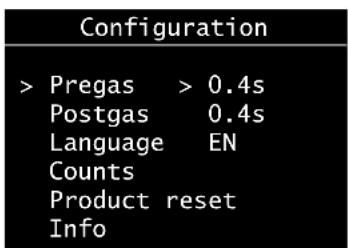
Press the G+ and G- keys to move the cursor on the left (Pre-gas, Post-gas, Language Reset machine, Information).
When the pre-gas, post-gas or language items are highlighted, press the D+ and D- keys to change their respective values.
| Range of settings Comment | ||
| Pegas NoGas | then 0.2 to 3 seconds | To weld with gas shielding, it is recommended to have a pre-gas of at least 0.4 seconds. |
| Post-gas NoGas | or 0.2 to 3 seconds | When welding is done with gas shielding, it is recommended to have a post-gas of at least 0.4 seconds. |
| Language FR, | GB, DE, NL, ES, IT, RU |
Push the return button to return to the Main Menu.
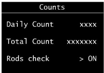
COUNTERS
When "Counters" is selected, the display shows:
- the log counter: number of welds made correctly since the product was put into operation. This counter is reset to zero when the product is restarted.
- the total counter: number of welds made correctly by the unit since it left the factory.
- The activation/deactivation of the warning message regarding checking the ground rods.
Press G+ and G- to switch ON or OFF.
Reset machine
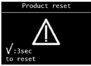
When the "Reset Machine" option is selected from the Configuration menu, pressing menu/enter opens the reset machine sub-menu.
Press menu/enter for 3 seconds to confirm product reset.
Push the return button to return to the Configuration menu and cancel resetting the unit.
Resetting the Alu side of the unit switches the product back to French, and the pre-gas and post-gas are reset to 0.4s.
Information panel
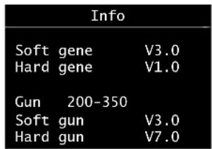
The information panel shows the software and hardware version numbers of the power source and gun.
UPDATE VIA USB
In order to benefit from new synergies and software improvements, it is possible to update the aluminium side via the USB socket on the front. To do so, contact the GYS service department and follow their instructions.
TOOLS FOR THE GUN

Optional, welding inserts on aluminium/steel is also possible with the accessories listed at the end of the manual (studs, insulation nail...).
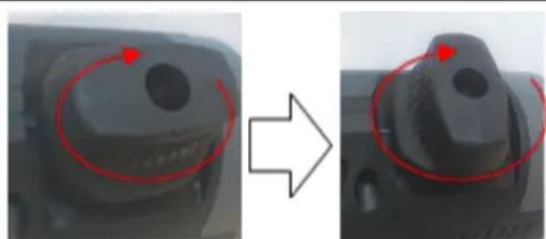
Loosen the locking knob so that the ground rods extend as far as possible from the gun.
Then tighten the locking knob.
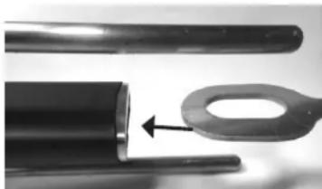
Unscrew the two cover screws and release the cover towards the front of the gun.
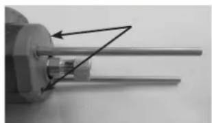
Slightly unscrew the two screws used to hold the rods.
If replacing the rod, remove the rods by pulling on them, then put a new one in.
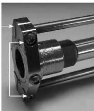
| Adjust the gun rods so that they are 120mm in length (measurement between the end of the rods and the edge of the flanges). | L |
| Tighten the two rod clamping screws. | |
| Replace the cover on the front of the gun and tigh-ten the two retaining screws. |
USE OF THE PULL RING ATTACHMENT
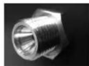
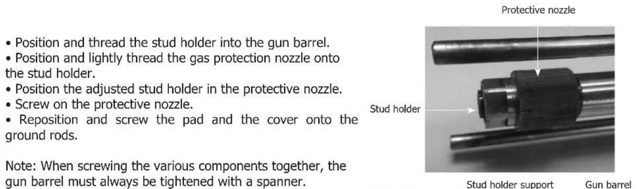
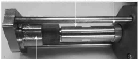
INSTALLATION OF A STUD HOLDER
| Slightly unscrew the knurled nut on the drive shaft of the gun. | |
| Position the ring holder until it stops and then tighten the knurled nut. | |
| Position the pull ring in the ring holder until it stops. |
Pad and cover
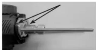
ADJUSTING A STUD HOLDER - INSULATION NAILS
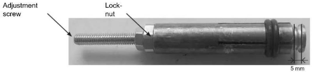
1) Unscrew the locking nut on the stud holder adjusting spindle.
2) Insert the attachment into the stud holder and adjust the screw so that the end of the attachment protrudes 5mm from it..
3) Screw on the locking nut.
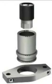
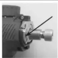
Installation of the earth rods pad and the protective gas cover:
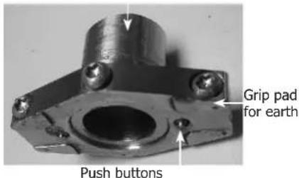
Protective gas cover
- Insert the gas protection cap into the grounding pad and lock it with the screw.
It is essential that the cap is placed on the other side of the pusher pad.
The gas shielding cover must not be mounted on the grounding pad when welding without any gas shielding.
- Put the pad (fitted with the cover) at the end of the ground rods and screw in the 2 clamping screws. It is recommended to place the pad with the clamping screws pointing down to the bottom of the gun to keep the positioning markings clearly visible.
Note: The use of gas protection and grounding pad is not necessary when welding a pulling ring.
Location markings
Clamping screw
ERRORMESSAGE,DEFECTS,CAUSES SOLUTIONS
This device has a fault monitoring system. In the event of a fault, error messages may be displayed.
| Error code Meaning Causes Solutions | |||
| OVERHEATING DEFECT | Generator thermal protection | Maximum duty cycle reached. | Wait for the indicator to turn off before resuming welding operations. |
| SECTOR DEFECT | Mains voltage default. | Mains power is out of range or one phase is missing. | Have your electrical installation checked by a qualified person. Reminder: the unit is designed to operate on a single-phase 110-240 Vac 50/60 Hz mains supply |
| PRESSED KEY | Keypad fault | A key on the keypad is pushed when the machine is switched on. | Ask a qualified person to check the key-pad. |
| COM. DEFECT | Communication fault with the gun | Communication between the gun and the power source is not working. | Reconnect the gun and switch the machine back on. If the fault remains, ask a qualified person to check the product. |
| OVERHEATING DEFECT | Gun thermal protection. | Maximum duty cycle reached. | Wait for the indicator to turn off before resuming welding operations. |
| MOTOR DEFECT | Wired temperature sensor fault. | The temperature sensor is disconnected. | Have the keypad checked by a qualified person. |
Note : All operations requiring the removal of the machine's cover and checking the electrical systems must be done by a qualified technician.
Steel function
The right-hand side of the product is used for the following bodywork operations:
- dent removal work,
- welding of nails, rivets, washers, studs and mouldings,
- removal of impacts,
- sheet metal retensioning.
It is not designed for the assembly of metal parts.
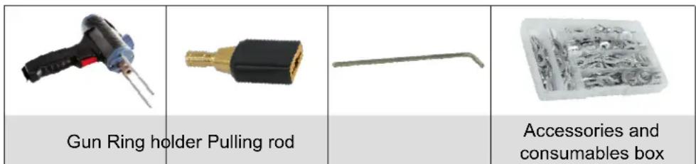
Delivered with the following steel accessories:
| Earth clamp Gun with trigger | Inertia hammer short 1,1kg | Accessories and consumables box |
START-UP AND SETTINGS
- Connect the gun (or guns) with the connectors.

The trigger gun has, in addition to the power connector, a connector for the control trigger. Connect the latter to initiate using the trigger.
- To switch the machine on, turn the knob (2) to the right (FIG-I p.2).
-
On first use:
-
The displays and indicator lights illuminate briefly and then the unit automatically enters SYNERGIC mode (12) (FIG-II p.2). It indicates:
-
the tool (1): set to 1 by default (star welding/slide hammer or Manuliner).
-
the power level (2): set to 2 by default (suitable for 0.8mm steel sheet).
To use the MANUAL mode (10), press key (8).
The SYNERGIC mode give to the user recommended factory settings for each tool used on a given sheet thickness.
he MANUAL mode allows the user to choose their own settings without the tool connected being taken into account, by selecting the desired power and spot time.
-
Depending on the mode chosen, SYNERGIC or MANUAL, change the settings as follows:
-
To change the tool, press the arrows (13) - (Available in SYNERGIC mode only).
| 1 K | 2 Q | 3 I | 4 J | 5 T | 6 O | 7 E |
| 1 Dent removal work using the inertia ham-mer, stars, or dent pulling clamp. | 5 Welding of rivets for sidewalk rods. | |||||
| 2 Welding rings for straightening work. | 6 Welding wavy wires or washers for earth attachments. | |||||
| 3 Impact shrinking with a specific copper tip. | 7 Welding studs for vehicle weights and linkages | |||||
| 4 Carbon electrode for retensioning. | ||||||
- To change the power level, press the arrows (9).
The power levels available allow the straightening of sheets of varying thickness.
- To change the spot time, press the arrows (7). - (Available in MANUAL mode only).
| Spot time (ms) | L 1 | 2 | 3 | 4 | 5 | 6 | 7 | 8 | 9 | H | |||||||
| 10 | 20 | 30 | 40 | 50 | 80 | 100 | 200 | 300 | 400 | 500 |
-
Using button (6), select the type of ignition (see ignition section):
-
the indicator (4) () denotes the use of a trigger gun.
-
the indicator (5) () denotes the use of an automatic gun (optional: ref. 050679).
-
Carry out the weld spot(s) in accordance with the operating instructions.
-
After first use, the steel side will be automatically be set to the settings of the last weld performed before the unit was switched off. It also records the last weld setting made for each tool and gun.
INSTRUCTIONS FOR USE
Operation
Proceed as follows:
1. Connect the ground clamp from the power source to the sheet metal workpiece to be straightened, following these guidelines:
- connect it as close as possible to the place to be welded.
- do not connect it to a neighbouring panel (e.g: do not connect the ground to a door in order to straighten the vehicle wing)
- cleanly strip the surface of the workpiece at the point of connection
2. Strip the area where the sheet is to be worked on.
3. Attach the required tool to the end of the gun, tightening the nut firmly.
4. Select the tool and the power.
5. Create contact between the gun tool and the workpiece.
6. Perform your spot weld.
Ignition
This function has 2 ignition systems:
Manual mode (using the trigger)
- Attach the power connector and the control connector,
- Press the ignition selection button (6) until the LED (4 - ) lights up (FIG-II p.2).
The automatic mode will no longer work, The automatic mode will no longer work, only pressing the trigger will enable the spot weld.
Automatic mode
- Connect the power connector,
- Press the ignition selection button (6) until the LED (5 - ) lights up (FIG-II p.2).
The machine is able to create the welding arc automatically.
The machine automatically detects the electrical contact and generates the spot weld in less than 1 second. To produce a 2nd spot, remove the contact at the end of the gun for at least half a second, and then reapply contact.

For best performance, it is recommended to use the ground cable and the guns that are supplied as standard.
THERMAL PROTECTION
This device is equipped with an automatic thermal protection system. This system will stop the machine to prevent it from overheating. It is indicated by the activation of the thermal fault light (7) (FIG-II p.2).
WARRANTY CONDITIONS
The warranty covers any defects or manufacturing faults for two years, from the date of purchase (parts and labour). The warranty does not cover:
- Any other damage caused during transport.
- The general wear and tear of parts (i.e: electrode holder, earth return rods, etc.).
- Incidents caused by misuse (incorrect power supply, dropping, disassembly).
- Faults due to the environment (pollution, rust, dust).
In the event of a fault, please return the appliance to your distributor, along with:
- a dated proof of purchase (receipt, invoice...)
a note explaining the malfunction.
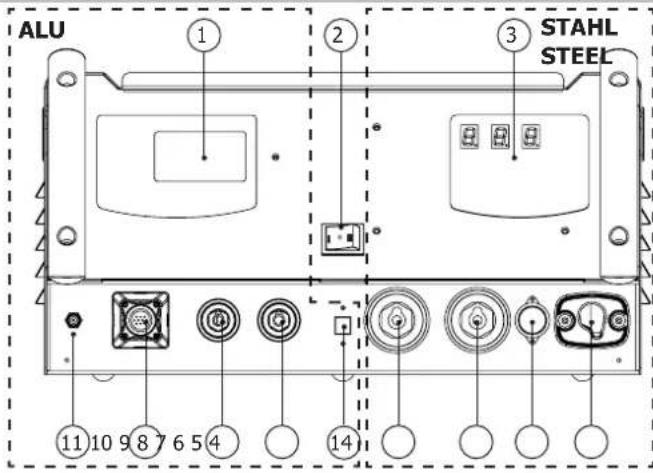
ABB. I
DE
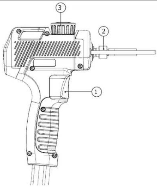
ABB. I - ALU-PISTOLE / ALU GUN
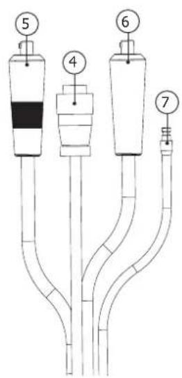
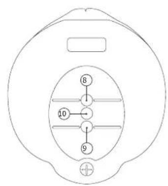
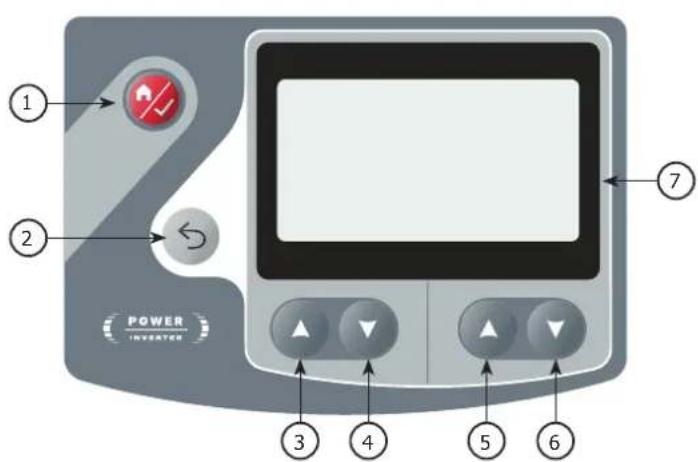
ABB. II - INTERFACE
ALU
STAHL / STEEL

> Bolzen
D. elect. M6
Material Fe
Gas ArCo8%
WAARSCHUWINGEN - VEILIGHEIDSINSTRUCTIES
ALGEMENE INSTRUCTIES

INSTALLATIE - WERKING VAN HET PRODUCT
BESCHRIJVING VAN HET MATERIALAAL (FIG-1)
THERMISCHE BESCHERMING
The duty cycles are measured according to standard EN60974-1 a 40^ and on a 10 min cycle. While under intensive use (> to duty cycle) the thermal protection can turn on, in that case, the arc switches off and the indicator switches on. Keep the machine's power supply on to enable cooling until thermal protection cancellation. The welding power source describes an external drooping characteristic.
ACCESSIONS / ACCESSORIES / ZUBEHÖR / ACCESSORIES / AKCECCYAPBI / ACCESSORI
Listenonexhaustive/Non-exhaustivelist
Porte-annneau / Ring holder / Ösentrager - für Pistole SPOT ARCPULL / Porta anillas / Dépkaçtenby koneu / Trekoog-houser / Portanello
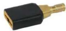
059610 059634 059641
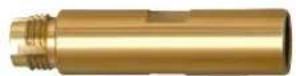
Support porte-goujon / threaded studs holder support / Gewindebolzenanschweißaufsatz / Soporte de permos / Onopa dinépkaTeNa rna3ka / Deuelhousersteun / Supporto porta vite /
Buse et coiffe de protection gaz ^+ patin pour pistolet spot arcpull / Gas protection nozzle ^+ pad for spot arcpull / Tobera de proteccion gas ^+ soporte para pistola spot arcpull / a303a山 Hoe conno ^+ noyuoka nra TocuHno yurobozabecb/ Gasbeschermingsmondstuk ^+ pad voor spot arcpull / Ugello protezione gas ^+ pattino per pistola spot arcpull /