ZIHS8TN - Distributor Zipper - Free user manual and instructions
Find the device manual for free ZIHS8TN Zipper in PDF.

| Type of product | Hydraulic log splitter |
| Brand | Zipper |
| Model | ZIHS8TN |
| Category | Splitter (log splitter) |
| Power supply | 400 V three-phase / 230 V single-phase, 50 Hz |
| Electrical protection | 30 mA residual current circuit breaker, max. 16 A fuse |
| Hydraulic system | Closed circuit with oil tank, pump and control valve |
| Recommended hydraulic oil | Shell Tellus 22, Mobil DTE 11, Aral Vitam GF 22 or BP Energol HLP-HM 22 |
| Splitting stroke | Adjustable (approximately 3–5 cm above logs) |
| Control | Two-hand control (safety) |
| Splitting wedge | Reinforced with treated cutting edge, sharpenable |
| Transport | Two wheels and transport handle |
| Operating conditions | Temperature: +5 °C to +40 °C; humidity max. 50%; altitude max. 1000 m |
| Cleaning | Water and mild detergent; do not use high-pressure cleaner |
| Maintenance | Lubrication of cylinders after each use; hydraulic oil change 1x/year |
| Safety | Protective devices, emergency stop, two-hand control |
| Spare parts | Available via Zipper website or customer service |
| Warranty | 2 years (excluding wear parts) |
Frequently Asked Questions - ZIHS8TN Zipper
User questions about ZIHS8TN Zipper
0 question about this device. Answer the ones you know or ask your own.
Ask a new question about this device
Download the instructions for your Distributor in PDF format for free! Find your manual ZIHS8TN - Zipper and take your electronic device back in hand. On this page are published all the documents necessary for the use of your device. ZIHS8TN by Zipper.
USER MANUAL ZIHS8TN Zipper
natural_image
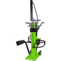
Green and black industrial machine with visible ZIPPER branding (no text or symbols on the device itself)ZI-HS8TN
EAN: 9120039234236
ZI-HS8TN\_230V
EAN: 9120039235660
CE
13.1 Intended use of the machine....20
13.1.1 Technical restrictions....20
13.1.2 Prohibited Use / Hazardous misapplications....20
13.2 User requirements....20
13.3 General safety instructions....20
13.4 Electrical safety 21
13.5 Special safety advice for these machines 21
13.6 Residual risks....21
14 TRANSPORT 22
15 ASSEMBLY 22
16 OPERATION....24
16.1 Preparatory activities....24
16.1.2 Greasing the ram / splitting wedge surface 24
16.1.3 Bleeding the hydraulic system....24
16.1.4 Checking the rotation direction of the motor 24
16.1.5 Check two-hand operation 24
16.2 Operating 25
16.2.1 Adjust the wedge ram stroke....25
16.2.2 Positioning the log 25
16.2.3 Adjusting the log holder 25
16.24 Splitting 25
16.2.5 Free a jammed log....25
17 CLEANING, MAINTENANCE, STORAGE, DISPOSAL....25
17.1 Cleaning 25
17.2 Maintenance....26
17.3 Maintenance plan 26
17.4 Hydraulic oil change 26
17.5 Sharpening Wedge 26
18 DISPOSAL 27
19 TROUBLESHOOTING....27
20 AVANT-PROPOS (FR)....28
21 SECURITE....29
21.1.1 Restrictions techniques....29
21.1.2 Applications interdites / Mauvaises applications dangereuses 29
32 UPORABA STROJA 42
32.1 Pripravljalna dela 42
32.1.1 Mesto postavitve 42
32.1.2 Mazanje bata/cepilnega klina....42
READ THE MANUAL! Read the user and maintenance carefully and get familiar with the controls in order to use the machine correctly and to avoid injuries and machine defects.
EN Do not remove or tamper with any protection or safety devices.
EN Dispose used oil in an environmental-friendly way!
EN Do not use in the rain!
EN Warning of hand injuries!
EN Do not remove jammed logs by hands!
EN Warning of crushing hazards!
EN Before starting any repair, maintenance or cleaning always disconnect device from the mains!
EN Avoid injury from the movement of the splitting blade.
EN Keep children and bystanders away from the work area!
EN Wear personal protective equipment!
EN Missing or non-readable security stickers have to be replaced immediately.
text_image
Technical diagram of a mechanical device with labeled parts and control panel| # | Beschreibung / Description / Description / Opis / Popis | Qty. |
| 1 | Holzspalter-Rahmen & Antriebseinheit / log splitter frame & power unit /Cadre fendeur de bois et unité d'entraînement / Okvir cepilnika polen in pogonska enota /Rám štípače & Jednotka pohonu | 1 |
| 2 | Kontrollhebel und Schutzarm / control lever and guard arm /Levier de contrôle et bras de protection / Upravljalna ročica in zaščitna roka /Ovládací páka a ochranné rameno | 2 |
| 3 | Einstellbarer Stammhalter / adjustable log holder (1 pair) / Support de trop réglable /Nastavljivo držalo polen / Nastavitelný držák polena | 2 |
| 4 | Halterung 1+2 / retainer 1 +2 / Fixation 1+2 / Držalo 1+2 / Držák 1+2 | 2 |
| 5 | Räder / wheels / Roues / Kolesa / Kola | 2 |
| 6 | Auflagetisch / support table / Plateau / Nalagalna miza / Podpůrný stůl | 1 |
| 7 | Bedienungsanleitung / manual / Mode d'emploi / Navodilo za uporabo / Návod k použití | 1 |
| 8 | Montagematerial / hardware / Matériel de montage / Montažni material / Spojovací materiál | 1 |
3.2 Komponenten / Components / Composants / Komponente / Komponenty
text_image
1 2 3 4 5 6 7 8 ZIPPER
text_image
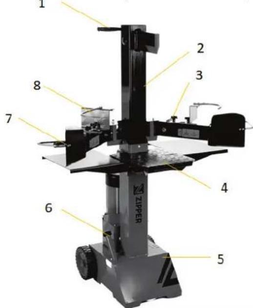
9 10 14 13 11 12| Bezeichnung / Description / Désignation / Oznaka | |
| 1 | Transportgriff / transport handle / Poignée de transport / Transportni ročaj / Transportní rukojeť |
| 2 | Zylinder / ram / Cylindre / Cilinder / Válec |
| 3 | Verstellknopf Stammhalter / log holder adjustment knob / Bouton de réglage du suppot de tronc / Gumb za nastavljanje držala polen / Seřizovací tlačítko držáku polena |
| 4 | Arbeitstisch / support table / Table de travail / Delovna miza / Pracovní stůl |
| 5 | Gestell / base / Châssis / Ogrodje / Základna |
| 6 | Ölmessstab-Öleinlassschraube – Tankentlüftung / oil tank cover –dip-stick - air bleeder / Jauge d'huile - vis d'admission d'huile - évent de réservoir / Merilna paličica za olje s čepom odprtine za dolivanje olja in odzračevanjem rezervoarja / Kryt nádrže oleje- Měrka oleje – Odvzdušnění nádrže |
| 7 | Bedienhebel / control lever / Manette de commande / Upravljalna ročica / Ovládací páka |
| 8 | Stammhalter / log holder / Support de tronc / Držalo polen / Držák polena |
| 9 | Einstellstange Verfahrweg / ram travel adjustment rod / Barre de réglage de la course de déplacement / Nastavitev delovnega giba / Nastavovací tyč pojezdu |
| 10 | Spaltkeil / split wedge / Couteau diviseur / Cepilni klin / Štípací klín |
| 11 | Bedienhebelschutz / control lever guard / Protection de la manette de commande / Zaščita upravljalne ročice / Kryt ovládací páky |
| 12 | Motor / motor / Moteur / Motor / Motor |
| 13 | Stecker-EIN-AUS-Schaltereinheit /plug ON-OFF-switch unit / Prise marche arrêt de l'unité de commutation / Enota vtiča in stikala za VKLOP/IZKLOP / Zásuvka-Spínací jednotka ON-OFF |
| 14 | Bedienhebel-Anschlussbügel / control lever connection bracket / Étrier de raccordement de la manette de commande / Priključno streme upravljalne ročice / Ovládací páka-připojovací konzoly |
3.3 Technische Daten / Technical Data / Données techniques / Tehnični podatki / Technické údaje
| Spezifikation / Specification / Spécifications / Tehnični podatki | ZI-HS8TN | ZI-HS8TN_230V |
| Motorleistung /motor power / Puissance du moteur / Moč motorja / Výkon motoru | 3500W S6 (40%) | 3000W S6(40%) |
| Spannung / voltage / Tension / Napetost / Napětí | 400 V (~3p) / 50 Hz | 230V / 50 Hz (13A) |
| Schutzklasse / IP-Protection class / Classe de protection / Zaščitni razred / Ochranná třída | IP54 ← | |
| Spaltgut-Durchmesser / log size capacity / Diamètre du bois à fendre / Premer cepljenca / Průměr polena | 8-30 cm | ← |
| Spaltgut-Länge / log size capacity / Longueur du bois à fendre / Dolžina polen / Délka polena | 10-50 cm ← | |
| Maximale Spaltkraft / maximum force / Puissance de fendage maxi-male / Maksimalna sila cepljenja / Maximální štípací síla | 8 t ← | |
| Hydraulikdruck / hydraulic pressure / Pression hydraulique / Hidravliční tlak / Hydraulický tlak | 21,0 MPa ← | |
| Hydrauliköl-Kapazität / hydraulic oil capacity / Capacité d'huile hyd-raulique / Prostornina rezervoarja za hidravlično olje / Objem hydrau-lického oleje | 4 l ← | |
| Verfahrweg Spaltkeil / ram travel / Course du coin à refendre / Gib cepilnega klina / Pojezd štípacího klínu | 48,5 cm ← | |
| Vorwärtsgeschwindigkeit / speed forward / Vitesse d'avance / Delovna hitrost giba naprej / Rychlost dopředu | 6 cm/s | 3,1 cm/s |
| Rückwärtsgeschwindigkeit / speed backward / Vitesse de recul / Delovna hitrost giba nazaj / Rychlost zpětného chodu | 19,4 cm/s 17,3 cm/s | |
| Lärmdruckpegel (LPA) / sound pressure level (LPA) / Niveau de pression acoustique (LPA) / Raven zvočnega tlaka (LPA) / Hladina akustického tlaku tlaka (LPA) | 77,8 dB(A) ← | |
| Vibrationspegel / vibration / Seuil de vibrations / Raven vibracij / Vi-brace | < 2,5 m/s2 ← | |
| Maschinenmaße (L x B x H) / machine dimension (L x W x H) / Dimen-sions de la machine (L x I x H) / Mere stroja (D x Š x V) / Rozměr stroje (D x Š x V) | 845 x 935 x 1500 mm | ← |
| Verpackungsmaße (L x B x H) / packaging dimension (L x W x H) / Di-mensions de l'emballage (L x I x H) / Mere embalažne enote (D x Š x V) / Rozměr balení (D x Š x V) | 560 x 400 x 1150 mm | ← |
| Gewicht (Netto) / weight (net) / Poids (net) / Masa (neto) / Hmotnost (netto) | 108,8 kg | ← |
| Gewicht (Brutto) / weight (gross) / Poids (brute) / Masa (bruto) / Hmotnost (brutto) | 115,9 kg | ← |
With the 3-phase 400 Volt / 50Hz motor, the log splitter should be connected to a standard 400 V ± 10% / 50 Hz ± 1% mains supply.
With the 1-phase 230 Volt / 50Hz motor, the log splitter should be connected to a standard 230 V ± 10% / 50 Hz ± 1% mains supply. The electrical supply must be equipped with protective devices against undervoltage, overvoltage, overcurrent and with a residual current protective device with a maximum rated residual current of 0.03 A. The mains connection cable must be connected to the mains supply. Mains connection cable and extension cable must be 5-core (400V) / 3-core (230V) = 3P + N + PE (3/N/PE) 400V, 1P+N+PE (230V). The mains connection must be fused with a maximum of 16 A. Rubber power cables must comply with EN60245 and be marked with the symbol "H 07 RN". The marking of
the cables is required by law. (FR) EXIGENCES ELECTRIQU
text_image
Technical diagram of a mechanical device with labeled components and dimension annotations1. Räder montieren:
text_image
Technical diagram showing a mechanical device and its corresponding assembly process with labeled parts.text_image
Technical diagram of a mechanical device with labeled parts and an inset showing internal components
text_image
Technical diagram of a mechanical device with labeled components A, B, and C, showing internal views and assembly details.natural_image
Close-up of a black mechanical component with numbered annotations (1, 2) pointing to features, no readable text or symbols beyond labels.text_image
Loosen the Covernatural_image
Technical line drawing of a mechanical component with concentric circles and mounting holes (no text or symbols)Phasenwender
text_image
Technical diagram of a mechanical device with labeled components A and B, showing internal components and directional arrows.natural_image
Technical line drawing of a mechanical assembly with labeled components (no text or symbols)text_image
Diagram showing two mechanical setups with arrows indicating force directions and a red X-shaped symbol crossed out, suggesting a comparison or comparison.text_image
Max. Min. Oil levelThis operating manual contains information and important notes for safe commissioning and handling of the log splitter ZI-HS8TN & ZI-HS8TN_230V, hereinafter referred to as "machine".

The manual is an integral part of the machine and must not be removed. Keep it for later use in a suitable place, easily accessible to users (operators), protected from dust and moisture, and enclose it with the machine if it is passed on to third parties!
Please pay special attention to the chapter Safety!
Before first use read this manual carefully. It eases the correct use of the machine and prevents misunderstanding and damages of machine.
Due to constant advancements in product design, construction, illustrations and contents may deviate slightly. If you notice any errors, please inform us.
We reserve the right to make technical changes!
Check the goods immediately after receipt and note any complaints on the consignment note when taking over the goods from the deliverer!
Transport damage must be reported to us separately to us within 24 hours.
ZIPPER MASCHINEN GmbH cannot accept any liability for transport damage that has not been reported.
Copyright
© 2022
This documentation is protected by copyright. All rights reserved! In particular, the reprint, translation and extraction of photos and illustrations will be prosecuted.
The place of jurisdiction is the regional court Linz or the court responsible for 4707 Schlüsslberg is valid.
Customer Service Address
This section contains information and important notes on the safe commissioning and handling of the machine.

For your safety, read this manual carefully before commissioning. This will enable you to handle the machine safely and thus prevent misunderstandings as well as personal injury and damage to property. Pay special attention to the symbols and pictograms used on the machine as well as the safety information and danger warnings!
13.1 Intended use of the machine
The machinery is intended exclusively for the following activities: Sweep of paved areas and paths; with mounted snow blade also for removing snow from private path in the specified limits.
NOTE

ZIPPER MASCHINEN GmbH assumes no responsibility or warranty for any other use or use beyond this and for any resulting damage to property or injury.
13.1.1 Technical restrictions
The machine is intended for use under the following ambient conditions:
Relative humidity: max. 50 %
Temperature (for operation): +5°C to +40°C
Temperature (Storage, Transport): -20^ C to +50^ C
Altitude above sea level up to 1.000 m
13.1.2 Prohibited Use / Hazardous misapplications
• Operation of the machine without adequate physical and mental aptitude
- Operating the machine without knowledge of the operating instructions
• Changes in the design of the machine
- Operating the machine under explosive conditions
- Operating the machine outside the specified power range
- Remove the safety markings attached to the machine.
- Modify, circumvent or disable the safety devices of the machine.
The improper use or disregard of the versions and instructions described in this manual will result in the voiding of all warranty and compensation claims against Zipper Maschinen GmbH.
13.2 User requirements
The machine is designed for operation by one person. The physical and mental aptitude as well as knowledge and understanding of the operating instructions are prerequisites for operating the machine. Persons who, because of their physical, sensory or mental abilities or their inexperience or ignorance, are unable to operate the machinery safely must not use it without supervision or instruction from a responsible person.
Please note that local laws and regulations may determine the minimum age of the operator and restrict the use of this machine!
Work on electrical components or equipment may only be carried out by a qualified electrician or under the instruction and supervision of a qualified electrician.
Put on your personal protective equipment before working on the machine.
13.3 General safety instructions
To avoid malfunctions, damage and health hazards when working with the machine, the following points must be observed in addition to the general rules for safe working:
- Check the machine for completeness and function before commissioning. Only use the machine if the guards and other protective devices required for the work are in place, in good working condition and correctly maintained.
- Select a level, vibration-free, non-slip surface as the installation site.
- Ensure that there is sufficient space around the machine!
- Ensure sufficient lighting conditions at the workplace to avoid stroboscopic effects.
• Ensure a clean working environment
• Use only defect-free tools that are free of cracks and other defects (e.g. deformation). - Keep the area around the machine free from obstacles (e.g. dust, chips, cut-off workpiece parts, etc.).
- Check the connections of the machine for strength before each use.
-
Never leave the running machine unattended. Switch off the machine before leaving the working area and secure it against unintentional or unauthorised restarting.
-
The machine may only be operated, maintained or repaired by persons who are familiar with it and who have been informed about the hazards that can occur during work.
- Ensure that unauthorised persons maintain an appropriate safety distance from the machine, and in particular keep children away from the machine.
- Never wear loose jewellery, loose clothing, ties or long, loose hair when working on the machine.
- Hide long hair under hair protection.
- Wear close-fitting protective work clothing and suitable protective equipment (eye protection, dust mask, ear protection; gloves only when handling tools).
• Always work carefully and with the necessary caution and never use excessive force. - Do not overload the machine!
- Switch off the machine and disconnect it from the power supply before adjusting, converting, cleaning, servicing or maintenance work etc. Before starting work on the machine, wait until all tools or machine parts have come to a complete standstill and secure the machine against unintentional restart.
- Do not work on the machine if you are tired, unconcentrated or under the influence of medication, alcohol or drugs!
- Do not use the machine in areas where vapours from paints, solvents or flammable liquids pose a potential danger (risk of fire or explosion!).
13.4 Electrical safety
• Make sure that the machine is grounded.
• Only use suitable extension cables.
- A damaged or tangled cable increases the risk of electric shock. Handle the cable with care. Never use the cable to carry, pull or disconnect the power tool. Keep the cable away from heat, oil, sharp edges or moving parts.
• Proper plugs and outlets reduce the risk of electric shock.
- Water entry into the machine increases the risk of electric shock. Do not expose the machine to rain or moisture.
- The machine may only be used if the power source is protected by a residual current circuit breaker.
• Use the machine only when the ON-OFF switch is in good working order.
• Before connecting the machine always make sure that it is switches off.
13.5 Special safety advice for these machines
- Do not split wet wood.
• Only split the wood upright in the direction of the grain! - Do not split wood containing foreign bodies such as nails, cables etc.
• Never operate the machine outdoors in the rain. - Select a level, vibration-free, non-slip surface for installation.
- Ensure sufficient light conditions at the workplace.
- Although it is possible that several operators could work on the machine (e.g. for loading and unloading), only one person may carry out the splitting operation any one time.
- Keep your hands away from splits and cracks that open in the log.
• Do not reach into the splitting area.
13.6 Residual risks
Despite proper use, certain residual risks remain. Due to the design and construction of the machine, hazardous situations may occur which are indicated as follows in these operating instructions:
DANGER

A safety instruction designed in this way indicates an imminently hazardous situation which, if not avoided, will result in death or serious injury.
WARNING

Such a safety instruction indicates a potentially hazardous situation which, if not avoided, may result in serious injury or even death.
CAUTION

A safety instruction designed in this way indicates a potentially hazardous situation which, if not avoided, may result in minor or moderate injury.
NOTE

A safety notice designed in this way indicates a potentially hazardous situation which, if not avoided, may result in property damage.
Irrespective of all safety regulations, your common sense and corresponding technical suitability and/or training remain the most important safety factor for fault-free operation of the machine. Safe working depends on you!
14 TRANSPORT
WARNING

Damaged or insufficiently strong hoisting devices and load slings can result in serious injuries or even death. Therefore, check hoists and load slings for sufficient load capacity and perfect condition before use. Attach the loads carefully. Never stand under suspended loads!
For proper transport, please also observe the instructions and information on the transport packaging regarding the centre of gravity, attachment points, weight, means of transport to be used and the prescribed transport position, etc.
Transport the machine in its packaging to the installation site. To manoeuvre the machine inside the packaging, you can use a pallet truck or a forklift with the appropriate lifting capacity. Ensure that the selected lifting equipment (crane, forklift, pallet truck, load sling, etc.) is in perfect condition.
For easier transport over short distances the machine has two wheels and a transport handle, the machine is heavy to avoid injury or damage, please note the following points:
- Hold the machine with both hands on the transport handle.
- Pay attention to the weight of the machine. If you are not able to hold the weight of the machine during transport, please ask for help.
- Only move the machine on firm and level ground to prevent it from tilting sideways or tipping completely over.
For transport, lower the cylinder, tighten the oil filler plug/air venting device, tilt the machine slightly backwards and move the machine on wheels using the handle.
15 ASSEMBLY
text_image
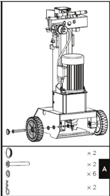
Technical diagram of a mechanical device with labeled components and dimension annotations1. Assemble the wheels
Pass the axle through the wheel from the outside and put two washers on it as shown in the picture. Slide the axle into the two holes at the base of the log splitter and secure it with another washer and an R-pin from the inside. Put on the wheel cap.

natural_image
Technical line drawing of a mechanical device with no visible text or symbols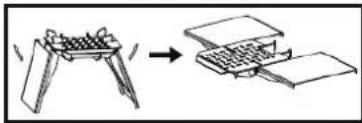
text_image
Diagram showing a folding or folding process with labeled parts and directional arrow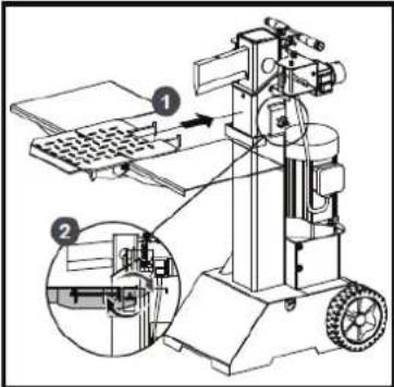
text_image
Technical diagram of a machine tool with labeled components and an inset close-up view showing internal structure.2. Assemble working table
- Before mounting, loosen the star knob by turning it anticlockwise.
- Unfold the log support table and make sure that the three parts are on the same surface level.
- Insert the hooks of the log support table into the brackets.
- Tighten the star knob
text_image
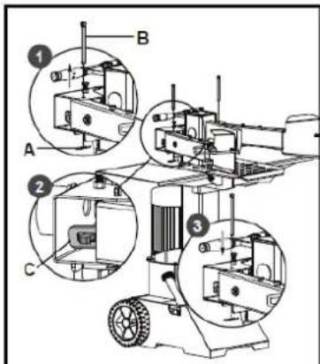
Technical diagram of a mechanical device with labeled components A, B, and C, showing internal views and assembly details.3. Assemble control lever
Pull the spring pin (A) to remove the locking pin (B). Apply a thin layer of grease to both surfaces of the operating lever guard (see figure). Insert the control lever and guard and make sure that the end of the control lever fits into the slot of the connecting bracket (C). Lock the control lever and the guard with the locking pin (B) and the spring pin (A) downwards. Follow the same steps to mount the control lever and the guard on the other side.
NOTE

Check both sides after assembly. The operating levers must be inserted in the slots of the connection brackets

text_image
M6 x 16 × 4 × 4 B4. Assemble adjustable log holder
Align the holes and assemble holder 1 and holder 2 on the log clamps. Pay attention to the direction of the holders as shown in the following figure. Secure the joint with M6x16 screws, washers and nuts. Secure the log clamps on the arm guards with star knobs and flat washers
natural_image
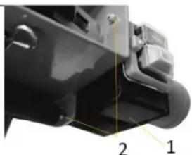
Close-up of a mechanical component with numbered callouts (1, 2) indicating parts of a housing or bracket (no readable text or symbols)5. Assemble plug-ON-OFF switch unit
Fix the unit (1) by means of 2 screws and nuts (2).
16 OPERATION
16.1 Preparatory activities
Place the log splitter on a flat and solid surface, which can bear the weight of the machine + load. Fix the log splitter to the ground through the two holes in the frame.
16.1.2 Greasing the ram / splitting wedge surface
Apply a thin layer of grease to the surface of the ram of your log splitter before starting work. This will prolong the life of the tool.
16.1.3 Bleeding the hydraulic system
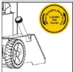
NOTE

Never forget to loosen the oil tank cap! Otherwise the air in the system will be compressed and released again and again, which will destroy the seals of the hydraulic circuit and make the log splitter unusable.
text_image
Longen the CoverVent the hydraulic system before starting the log splitter.
To do this, loosen the cover of the hydraulic oil tank by a few turns until the air can flow in and out gently.
The airflow through the oil tank should be visible during operation.
To prevent oil from leaking out, the oil tank cover must be tightly closed before each transport!
16.1.4 Checking the rotation direction of the motor (400V)
NOTE

Never run the motor in the wrong rotation direction. This will damage the pump and void the warranty.

natural_image
Technical line drawing of a circular electronic component with mounting holes and a pointer, no text or symbols present.Phase inverter
Check the rotation direction of the motor. If necessary reverse the polarity of the motor using a screwdriver (phase inverter inside the plug - see picture on the left).
16.1.5 Check two-hand operation
Before using the machine for the first time, make sure that the two-hand control is working properly by following the steps below:
(1) Lower both control levers, the splitting wedge lowers to 5 cm above the highest table position.
(2) Release one of the two levers, the splitting wedge should be in original position
(3) Release both levers, the ram should automatically rise to the highest position.
16.2 Operating
16.2.1 Adjust the wedge ram stroke

text_image
Technical diagram of a mechanical device with labeled components A and B, showing internal components and directional arrows.To set the return stroke position of the cylinder, proceed as follows:
(1) Move the splitting wedge to the desired position. The upper position of the splitting wedge should be about 3\~5cm above the logs to be split.
(2) Release a control lever or switch off the motor.
(3) Loosen the adjusting screw (A). Lift the adjusting rod
(B) until the adjusting rod (B) is stopped by the spring inside. Tighten the adjusting screw (A).
(4) Release both control levers or switch on the motor.
(5) Check the upper position of the splitting wedge.
16.2.2 Positioning the log
Place the log vertically and flat on the support table. Make sure that the splitting wedge and the support table touch the log at right angles at the ends. Never try to split a log at an angle.
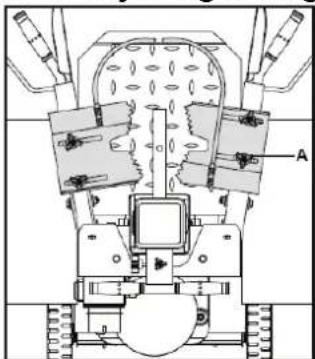
16.2.3 Adjusting the log holder
natural_image
Technical line drawing of a mechanical assembly with gears and components (no text or symbols)Adjust the log holders (A) according to the diameter of the log to obtain the most comfortable angle of the control lever
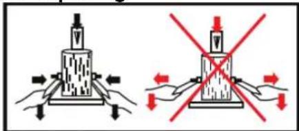
16.2.4 Splitting
text_image
Diagram showing two methods of using a mechanical device with red prohibition signs indicating resistance or force.Hold the log with clamps.
Press the levers down to start splitting.
Releasing one of the two levers stops the movement of the splitting wedge.
Release both levers to move the splitting wedge back to the upper position.
16.2.5 Free a jammed log
Stack as you work. This will provide a safer work area, by keeping it uncluttered, and avoid the danger of tripping, or damaging the power cord.
17 CLEANING, MAINTENANCE, STORAGE, DISPOSAL
WARNING

Before carrying out any maintenance work, ensure that moving parts are stationary, that the machine is disconnected from the mains supply.
17.1 Cleaning
Clean the machine and the working attachment from soil, dust, grass, chips, and small twigs, etc.
NOTE

The use of solvents, harsh chemicals or abrasive cleaners leads to damage to the machine!
Therefore: When cleaning, use only mild detergent. The use of high pressure cleaners is not recommended. It shortens the service life and reduces the operational integrity. (Water can get into the gear!)
Impregnate bare surfaces of the machine against corrosion (e.g., anti-rust WD40).
17.2 Maintenance
The machine does not require extensive maintenance. If malfunctions and defects occur, let it be serviced by trained persons only.
NOTE

Only a properly maintained equipment may be a satisfactory tool. Care and maintenance deficiencies can cause unpredictable accidents and injuries. Repairs should be performed only by authorized service centers.
Improper operation may damage the equipment or endanger your safety.
17.3 Maintenance plan
| Grease / cleaning the ram | After each use |
| Check oil level | After each oil change or every 8 operating hours |
| Change hydraulic oil | 1 x per year |
17.4 Hydraulic oil change
NOTE

Check the oil level regularly. Change the hydraulic oil completely at least once a year. Always dispose of used oil correctly and never throw it into household waste or sewage!
The hydraulic system of the log splitter is a closed system with oil tank, oil pump and control valve. The oil should be changed completely once a year.
The following hydraulic oils are recommended for the hydraulic transmission system of the log splitter:
- Shell Tellus 22
- Mobil DTE 11
• Aral Vitam GF 22 or
• BP Energol HLP-HM 2

flowchart
graph TD
    A["Max."] --> B["Vertical Output"]
    C["Min."] --> B
    B --> D["Oil level"]
If the oil level is too low, the oil pump can be damaged, whereas overfilling can lead to overheating of the hydraulic system. Therefore check the oil level regularly with the dipstick - see picture on the left!
NOTE

Hydraulic oils are toxic and must not be released into the environment!
Follow the manufacturer's instructions and contact your local authorities for information on proper disposal.

Change the hydraulic oil:
- Remove the oil drain plug to drain the oil from the hydraulic system.
- Use a drip pan to collect waste oil and particles.
- Inspect the oil for metal chips. (Metal chips in the oil are an indication of increased wear.)
- After the oil has been completely drained from the machine, reinstall the drain plug.
- Top up the recommended fresh hydraulic oil via the oil filler plug.
- After changing the oil, actuate the wood splitter several times without actually splitting any wood.
- Use a dipstick to check the oil level.
17.5 Sharpening Wedge
This log splitter is equipped with reinforced splitting wedge which blade is specially treated. After long periods of operation, and when required, sharpen the wedge using a fine toothed file removing any burrs or flat spots on the edge.
18 DISPOSAL

Observe the national waste disposal regulations. Never dispose of the machine, machine components or equipment in residual waste. If necessary, contact your local authorities for information on the disposal options available. If you buy a new machine or an equivalent device from your specialist dealer, he is obliged in certain countries to dispose of your old machine properly.
19 TROUBLESHOOTING
WARNING

Danger due to electrical voltage!
Handling the machine with connected power supply may result in serious injury or death. → Always disconnect the machine from the power supply before maintenance or repair work and secure it against unintentional reconnection.
Many possible sources of error can be excluded in advance if the machine is properly connected to the mains. If you are unable to carry out necessary repairs properly and/or do not have the required training, always consult a specialist to solve the problem.
| PROBLEM | PROBABLE CAUSE | REMEDY SUGGESTED |
| Motor does not start | Switch is Off | Set switch to On |
| Incorrect motor rotation direction | Incorrect connection | Use the phase inverter to change the polarity of one of the phases on the motor. |
| Log Splitter does not work while motor running | Valve is not opened owing to the connection parts loosening | Check and tighten the parts |
| Control Levers or connection parts bent | Repair the bent parts | |
| Lower hydraulic oil level | Check and refill hydraulic oil | |
| Log Splitter works with abnormal vibration and noise | Lower hydraulic oil level | Check and refill hydraulic oil |
20 AVANT-PROPOS (FR)
Cher client, chère cliente,
21.1.1 Restrictions techniques
text_image
Technical diagram of a mechanical device with labeled components and dimension annotationstext_image
Technical diagram illustrating a machine tool operation with labeled steps and component viewstext_image
Technical diagram of a machine with labeled components and cross-sectional viewsnatural_image
Close-up of a black mechanical component with numbered parts (1 and 2) and no visible text or symbols.text_image
Borrow Operation, Buy to Buy Loosen the Covernatural_image
Technical line drawing of a mechanical component with mounting holes and a diagonal line indicating direction (no text or symbols)Inverseur de phase
text_image
Technical diagram of a mechanical device with labeled components A and B, showing assembly or assembly steps.natural_image
Technical line drawing of a mechanical assembly with labeled components (no text or symbols)text_image
Diagram showing two methods of compressive load application: one with downward force arrows and another with red prohibition signs.text_image
Technical diagram of a mechanical device with labeled components and a zoomed-in view showing measurement ranges.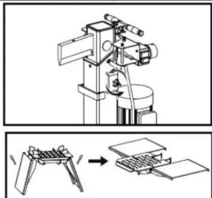
natural_image
Technical illustration of a mechanical device with a base and tool, showing a process from assembly to processing (no text or symbols present)1. Montaža koles:
text_image
Technical diagram of a machine tool with labeled parts and an inset showing close-up details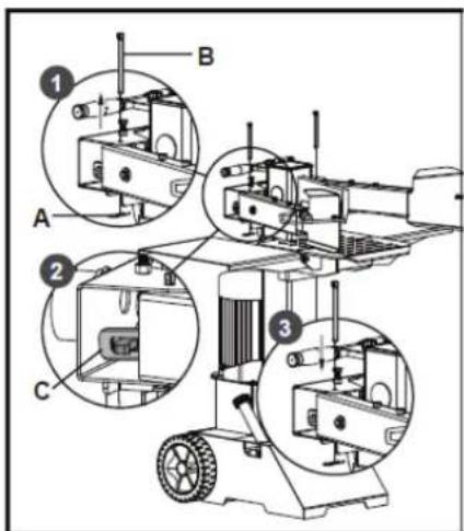
text_image
Technical diagram of a machine with labeled components and three circular insets showing close-ups of parts A, B, and C.
text_image
M6 x 16 × 4 × 4 B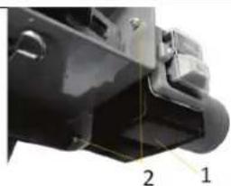
natural_image
Close-up of a black mechanical component with numbered callouts (1 and 2), no visible text or symbols.text_image
B. Christian, Dr. E. A. Loosen the Cover A.D.Pred zagonom cepilnika polen odzračite hidravlični sistem.
natural_image
Technical line drawing of a mechanical component with concentric circles and mounting holes (no text or symbols)Menjalnik faze
text_image
Technical diagram of a mechanical device with labeled components A and B, showing internal components and directional arrows.natural_image
Technical line drawing of a mechanical assembly with labeled component A (no text or symbols present)text_image
Diagram showing two experimental setups with arrows indicating force directions and a red X-shaped symbol in the second setup.S prižemnima stremenoma pridržujte poleno.
text_image
Technical diagram of a mechanical device with labeled components and a corresponding numerical input box showing measurements ×2, ×2, ×6, and ×2.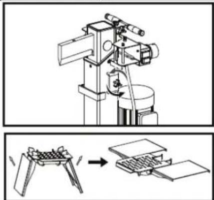
text_image
Technical diagram showing a mechanical device with rotating components and a close-up of its internal structure, likely illustrating a mechanical assembly or processing process.1. Montáž kol:
text_image
Technical diagram of a machine tool with labeled components and an inset showing close-up views of the mechanism.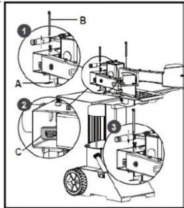
text_image
Technical diagram of a machine with labeled components and cross-sectional viewsnatural_image
Close-up of a black mechanical component with numbered annotations (1, 2) pointing to features, no readable text or symbols beyond labels.text_image
Open Operation, B#### Loosen the Covernatural_image
Technical line drawing of a mechanical component with mounting holes and a central circular feature (no text or symbols)Fázový měnič
text_image
Technical diagram of a mechanical device with labeled components A and B, showing internal components and directional arrows.natural_image
Technical line drawing of a mechanical assembly with labeled component A (no text or symbols beyond label)text_image
Diagram showing two methods of lifting a weight with red prohibition signs, indicating no lifting or no tension.text_image
400 V N L1 L2 L3 PE SB1 E KM M SB2 230 V U J MR SB2 FF M C45 HYDRAULIKSCHEMA / HYDRAULIC SCHEME / SCHÉMA HYDRAULIQUE / HIDRAVLIČNA SHEMA / SCHÉMA HYDRAULICKÉHO SYSTÉMU

flowchart
graph TD
    A["Hydraulic Pump"] --> B["Valve"]
    B --> C["Directional Valve"]
    C --> D["Motor M"]
    D --> E["Return Line"]
    E --> F["Ground"]
    style A fill:#f9f,stroke:#333
    style B fill:#ccf,stroke:#333
    style C fill:#cfc,stroke:#333
    style D fill:#fcc,stroke:#333
    style E fill:#cff,stroke:#333
46 ERSATZTEILE / SPARE PARTS / PIECES DE RECHANGE / NADO-MESTNI DELI / NAHRADNI DILY
(EN) With original ZIPPER spare parts you use parts that are attuned to each other shorten the installation time and elongate your products lifespan.
NOTE

The installation of parts other than original spare parts leads to the loss of the guarantee! Therefore: When replacing components/parts, only use spare parts recommended by the manufacturer.
Order the spare parts directly on our homepage – category SPARE PARTS or contact our customer service
• via our Homepage – category SERVICE/NEWS - SPARE PARTS REQUEST,
• by e-mail to eg01@zipper-maschinen.at.
Always state the machine type, spare part number and designation. To prevent misunderstandings, we recommend that you add a copy of the spare parts drawing with the spare parts order, on which the required spare parts are clearly marked especially when not using the online-spare-part catalogue.
text_image
Technical diagram of a mechanical assembly with numbered components and labeled parts| No. | Description | Q'ty |
| 1 | Side Log Support 2 | 1 |
| 2 | Side Log Support 1 | 1 |
| 3 | Locknut M8 | 4 |
| 4 | Washer 8 | 8 |
| 5 | Spring | 2 |
| 6 | Bush | 2 |
| 7 | Bolt 8.8 M8x210 | 2 |
| 8 | Log Support C1 | 1 |
| 9 | Bolt 8.8 M8x60 | 2 |
| 10 | Bush 2 | 2 |
| 11 | Lining Plate | 4 |
| 12 | Clip 2.5 | 2 |
| 13 | Handle C1 | 2 |
| 14 | Handgrip | 4 |
| 15 | Guard Ring C1 | 2 |
| 16 | Screw M6x16 | 8 |
| 17 | Washer 6 | 6 |
| 18 | Locknut M6 | 8 |
| 19 | Right Armguard C1 | 1 |
| 20 | Retainer 1 | 1 |
| 21 | Star Knob | 4 |
| 22 | Big Washer 8 | 11 |
| 23 | Left Armguard C1 | 1 |
| 24 | Bush 1 | 2 |
| 25 | Pin C1 | 2 |
| 26 | Star Knob M6 | 1 |
| 27 | Cap | 2 |
| 28 | Retainer 2 | 1 |
| 29 | Clamp | 2 |
| 30 | Splitting Pipe G5 | 1 |
| 31 | Square Cap | 1 |
| 32 | Star Knob M5(black) | 1 |
| 33 | Upper Lining Plate 2-C | 1 |
| 34 | Upper Lining Plate 4 | 1 |
| 35 | Upper Lining Plate 3 | 1 |
| 36 | Upper Lining Plate 1 | 1 |
| No. | Description | Q'ty |
| 37 | Screw M6x8 | 1 |
| 38 | Locknut M4 | 2 |
| 39 | Switch | 1 |
| 40 | Screw M4x60 | 2 |
| 41 | Motor | 1 |
| 42 | Screw M6x10 | 1 |
| 43 | Washer 16 | 7 |
| 44 | Pull Rod G5 | 1 |
| 45 | Lever C1 | 1 |
| 46 | Cylinder C1 | 1 |
| 47 | Circlip 22 | 4 |
| 48 | Bolt M8x50 | 2 |
| 49 | Nut M8 | 5 |
| 50 | Main Frame C1 | 1 |
| 51 | Short Shaft D | 1 |
| 52 | Tube C1 | 1 |
| 53 | Star Knob (black) | 1 |
| 54 | Oil Plug A1 | 1 |
| 55 | Washer Groupware 20 | 10 |
| 56 | Oil Hose C1 | 1 |
| 57 | Collar | 1 |
| 58 | Gear Pump C1 | 1 |
| 59 | Nozzle C1 | 1 |
| 60 | Oil Plug A2 | 2 |
| 61 | Hose Clamp 18-23(24) | 4 |
| 62 | Oil Hose 13 | 1 |
| 63 | Oil Hose C1 | 1 |
| 64 | Nozzle A | 1 |
| 65 | CCA Valve | 1 |
| 66 | Oil Cap K | 1 |
| 67 | Oil Dipstick KG | 1 |
| 68 | Screw M8x90 | 2 |
| 69 | Spring Washer 8 | 7 |
| 70 | O-Ring 25x2.65 | 1 |
| 71 | Big Washer 10 | 3 |
| 72 | Motor Support | 3 |
| No. | Description | Q'ty |
| 73 | Bolt 8.8 M8x45 | 3 |
| 74 | Oil Plug A6 | 1 |
| 75 | Oil Hose C1 | 1 |
| 76 | Oil Hose 13 | 1 |
| 77 | Screw M8x35 | 2 |
| 78 | Shield C1 | 1 |
| 79 | Big Washer 6 | 3 |
| 80 | Screw M6x10 | 5 |
| No. | Description | Q'ty |
| 81 | Clip 3 | 2 |
| 82 | Washer Groupware 16 | 1 |
| 83 | Bolt M16x25 | 1 |
| 84 | Wheel | 2 |
| 85 | Wheel Axle C1 | 2 |
| 86 | Wheel Cap | 2 |
| 87 | Long Shaft A4 | 1 |
| 88 | Clip 4 | 1 |
ZIPPER machines are subject to the legal warranty, which is valid in the current version. (For electrical and mechanical components, this is equivalent to 2 years (excluding wearing parts and batteries), starting from the date of purchase by the end user/buyer. For rechargeable batteries and batteries, the legal warranty of 6 months applies, starting from the date of purchase by the end user/buyer). In case of defects during this period, which are not excluded by paragraph 3, ZIPPER will repair or replace the machine at its own discretion.
2.) Report:
In order to check the legitimacy of warranty claims, the final consumer must contact his dealer. The dealer has to report in written form the occurred defect to ZIPPER. If the warranty claim is legitimate, ZIPPER will pick up the defective machine from the dealer. Returned shippings by dealers which have not been coordinated with ZIPPER, will not be accepted and refused.
3.) Regulations:
a) Warranty claims will only be accepted, when a copy of the original invoice or cash voucher from the trading partner of ZIPPER is enclosed to the machine. The warranty claim expires if the accessories belonging to the machine are missing.
b) The warranty does not include free checking, maintenance, inspection or service works on the machine. Defects due to incorrect usage of the final consumer or his dealer will not be accepted as warranty claims either. Some examples: usage of wrong fuel, frost damages in water tanks, leaving fuel in the tank during the winter, etc.
c) Defects on wear parts are excluded, e.g. carbon brushes, collection bags, knives, cylinders, cutting blades, clutches, sealings, wheels, saw blades, splitting crosses, riving knives, riving knife extensions, hydraulic oils, oil/air/fuel filters, chains, spark plugs, sliding blocks, etc.
d) Also excluded are damages on the machine caused by incorrect or inappropriate usage, if it was used for a purpose which the machine is not supposed to, ignoring the user manual, force majeure, repairs or technical manipulations by not authorized workshops or by the customer himself, usage of non-original ZIPPER spare parts or accessories.
e) After inspection by our qualified personnel, resulted costs (like freight charges) and expenses for not legitimated warranty claims will be charged to the final customer or dealer.
f) In case of defective machines outside the warranty period, we will only repair after advance payment or dealer's invoice according to the cost estimate (incl. freight costs) of ZIPPER.
g) Warranty claims can only be granted for customers of an authorized ZIPPER dealer who directly purchased the machine from ZIPPER. These claims are not transferable in case of multiple sales of the machine.
4.) Claims for compensation and other liabilities:
The liability of company ZIPPER is limited to the value of goods in all cases. Claims for compensation because of poor performance, lacks, damages or loss of earnings due to defects during the warranty period will not be accepted. ZIPPER insists on its right to subsequent improvement of the machine.
SERVICE
After Guarantee and warranty expiration specialist repair shops can perform maintenance and repair jobs. But we are still at your service as well with spare parts and/or product service. Place your spare part/repair service cost inquiry by
- Mail to service@zipper-maschinen.at.
- Or use the online complaint order formula provided on our homepage – category SERVICE/NEWS.
51 DÉCLARATION DE GARANTIE (FR)
1.) Garantie
(EN) We monitor the quality of our delivered products in the frame of a Quality Management policy.
Your opinion is essential for further product development and product choice. Please let us know about your:
- Impressions and suggestions for improvement.
- Experiences that may be useful for other users and for product design
- Experiences with malfunctions that occur in specific operation modes
We would like to ask you to note down your experiences and observations and send them to us via E-Mail or by post: