
SG1800 - Cooker ABUS - Free user manual and instructions
Find the device manual for free SG1800 ABUS in PDF.
| Product type | Compact alarm siren |
| Brand | Abus |
| Model | SG1800 / SG1805 / SG1810 |
| Dimensions (H x W x D) | 300 x 220 x 91 mm |
| Weight (without battery) | 2.0 kg |
| Main power supply | 13.8 V DC, 1.6 A (PS terminals) or 200 mA (AUX/COM terminals) |
| Backup power supply | Battery 12 V / 2.1 Ah |
| Standby consumption | 54 mA + battery charge (max 140 mA) |
| Operating consumption | 1.6 A (siren + flash) |
| Sound level | 106 dB at 3 m |
| Siren frequency | 1500 - 1800 Hz |
| Flash | LED SLT, 6000 mcd, frequency 60 Hz |
| Protection | IP43, IK06 |
| Operating temperature | -25 °C to 70 °C |
| Max. relative humidity | 95% |
| Main functions | Robust outdoor siren, weather-resistant, Flash-LED technology, pivoting polycarbonate housing, metal inner housing, adjustable duration and signal, input protected against overvoltage and reverse polarity, inputs for positive or negative control signals, fault output and status LED, backup battery with automatic charging and deep discharge protection, tamper monitoring via cover contact and anti-removal |
| Maintenance and cleaning | Clean with a dry, soft cloth. Do not open the device. |
| Safety | Never open when powered. Do not modify or alter the device. Observe the temperature and environmental class limits. Avoid shocks and vibrations. |
| General information | Manual available in several languages. Complies with European directives. Manufactured by Security-Center GmbH & Co. KG. |
Frequently Asked Questions - SG1800 ABUS
User questions about SG1800 ABUS
0 question about this device. Answer the ones you know or ask your own.
Ask a new question about this device
Download the instructions for your Cooker in PDF format for free! Find your manual SG1800 - ABUS and take your electronic device back in hand. On this page are published all the documents necessary for the use of your device. SG1800 by ABUS.
USER MANUAL SG1800 ABUS
Installation Instructions (UK) 11
Euro compact alarm Installation Instructions
SG1800 / SG1805 / SG1810
1. Preface
Dear Customer,
Thank you for purchasing this compact alarm. This equipment is produced with state-of-the-art technology, which complies with the current standards of domestic and European regulations. The CE has been proven and all related certifications are available from the manufacturer upon request (www.security-center.org). To ensure proper and safe operation, it is your obligation to observe these installation instructions!
In the event of questions, please contact your local specialist dealer.
2. Safety information
To reduce the risk of electric shock when it is in use and to ensure that your guarantee remains valid, do not open the equipment.
No part of the product may be changed or modified in any way!
Avoid greater physical stress of the equipment (knocks, vibrations, etc.). Incorrect handling and bad transport conditions can lead to damage to the equipment.
The compact alarm must only be used within the prescribed temperature and protection class ranges. Using the equipment outside the prescribed ranges results in greater wear and early failure. For details, see the technical data at the end of these instructions.
We want you to work only with products that incorporate state-of-the-art technology. For this reason, we reserve the right to make technical modifications and to make changes to these instructions without prior notice.
© Security-Center GmbH & Co. KG, February 2008
3. Main features
- Robust, weatherproof external sounder
High-volume 106 dB sounder - LED strobe technology with a long service life and low power consumption
- Turnable polycarbonate housing
- Internal metal casing to prevent tampering
- Adjustable sounder duration and signal
- Input protected to over-voltage and polarity reversal
- Inputs for positive or negative trigger signal
- Trouble output and status LED
- Backup power supply from battery (12 V/2.1 Ah)
- Auto-recharging battery circuit with automatic disconnection against battery deep discharge.
- Tamper protection through wall and cover contact
4. Scope of delivery
- 1 x compact alarm
- 1 x installation instructions
- 1 x drill template
- 4 × screws (DIN 7981; 3.9 ~mm × 32 ~mm )
5. Installation
- Open the front cover by unscrewing and removing the fixing screw on the bottom of the compact alarm.
- Use the template to mark the drill holes on the surface on which you want to mount the alarm.
- Drill the holes and insert wallplugs.
- Pull the connection cables through the backplate of the sounder.
- Screw the backplate of the sounder firmly to the mounting surface.
- Remove the internal metal casing by unscrewing and removing the lower screw.
- Wire up the compact alarm and set the jumpers and dip-switches according to the required behaviour (see next section, "6. Putting into operation").
- Connect the battery (12 V/2.1 Ah) for the backup power supply.
- Replace the internal metal casing and close it with the screw, and do the same for the front cover.
6. Putting into operation
IMPORTANT:
Before connecting, make sure that the power supply is switched off!
6.1 LED indication
| LED | Description |
| POWER | The power LED shows the operating state of the sounder. |
| ON: Power supply is applied to the sounder. | |
| OFF: No power supply to the sounder. | |
| FLASHING: Sounder trouble. | |
| LED2 | Status LED |
| ON: Input signal at LED input. | |
| OFF: No signal at input. | |
| IMPORTANT: | |
| The signal to the LED is user-defined, e.g.: alarm system set. But you can also combine the input of the Status LED with the output of the fault output (TRBL). |
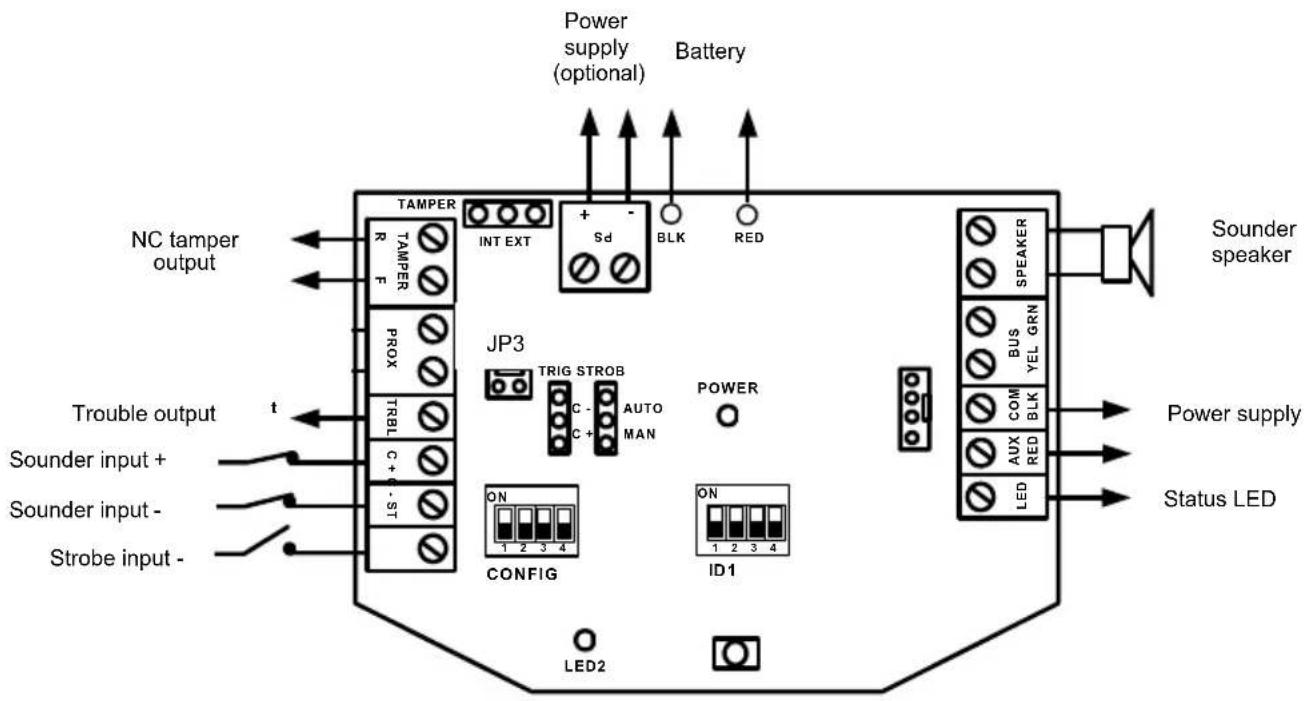
6.2 Jumper settings
| Setting | Description |
| STROB(Default: AUTO)STROB AUTO STROB MAN | Defines the strobe operation mode.AUTO: The strobe follows the sounder triggering.MAN: The strobe follows the triggering of the ST input. |
| TRIG(Default: C+)TRIG C +TRIG C - | Setting of the trigger potential of sounder.C+: Use the C+ connection to activate the sounder(Terminal C- is deactivated).C-: Use the C- connection to activate the sounder(Terminal C+ is deactivated). |
| TAMPER(Default: EXT)TAMPEREXT TAMPER TAMPER INT | Defines the tamper output operation (wall and cover contact).EXT: The NC tamper output is for connection to an external tamper line.1 PIN (no connection):As for the EXT setting, the tamper output is for connection to an external tamper line. However, there is an internal series-connected 2K2 resistor for the EOL connection.INT: Not used. |
6.3 DIP-switch settings
| CONFIG configuration | Description |
| CONFIG: 1(Default: OFF) | Defines the operation of the trouble output (TRBL).ON: Switches in the event of battery faults (low voltage or charging fault), input voltage or sounder faults.OFF: Switches only for battery faults (low voltage or charging fault). |
| CONFIG: 2(Default: OFF) | The OFF setting must not be changed! |
| CONFIG: 3(Default: OFF) | Defines the maximum sounder duration.ON: 5 minutesOFF: 3 minutes |
| IMPORTANT: | |
| The sounder activation always ends if there is no longer a trigger signal at the C+/C- connectors! | |
| CONFIG: 4(Default: OFF) | Defines the sounder sound.ON: SlowOFF: Fast |
| Configuration ID1 | Description |
| ID1: 1-3(Default: All OFF) | Not used. |
| ID1: 4(Default: OFF) | Selection of sounder signal according to French Standard NFA2P.ON: French StandardOFF: Normal Standard |
6.4 Wiring
| Terminal Description | |
| LED | Connector for LED2. The LED lights up for a negative trigger signal (0 V DC at input). |
| AUX RED COM BLK | Standard connections for power supply (13.8 V DC/200 mA max.). |
| BUS YEL / BUS GRN | Not used. |
| SPEAKER | Connections for the sounder speaker (8 Ohm, 30 W). |
| BLK RED | Connections for the backup power supply (12 V/2.1 Ah). The battery is charged automatically by the auto-recharging battery circuit. |
| PS + PS - | Optional connections for power supply (13.8 V DC/1.6 A). |
| IMPORTANT: | |
| If you use a battery, there is no need to connect these terminals! | |
| These connections are required if you do not want to use a battery. The maximum current from these connections is 1.6 A. The AUX RED and COM BLK connections can be left free. | |
| IMPORTANT: | |
| Make sure that the power source supplies the necessary current of 1.6 A; otherwise, the alarm system cannot work correctly! Note that the compact alarm has no backup power supply if connected like this! | |
| TAMPER R TAMPER F | Tamper connections for wall and cover contact. The connection of the contacts depends on the TAMPER jumper. |
| JP3 (PCB) | The tamper contacts are connected to the JP3 pins. |
| PROX (N.C) | Not used. |
| TRBL (N.O) | The reaction of the trouble output depends on the setting of the dip-switch (CONFIG 1). |
| C+ | • Connected to +12 V =>>> sounder is off • Loss of +12 V signal (or switch to 0 V) =>>> sounder is activated |
| C- | - Connected to 0 V »»» sounder is off - Loss of 0 V signal (or switch to 12 V) »»» Sounder is activated |
| ST | - Connected to 0 V »»» Strobe is activated - Loss of 0 V signal (or switch to 12 V) »»» Strobe is off |
| IMPORTANT: | |
| The separate strobe control works only if the STROB jumper is set to MAN! |
IMPORTANT:
- The sounder does not work if no battery is connected or no backup power supply is connected to the PS connectors.
- To prevent false alarms, the sounder and strobe do not operate for 20 seconds after powering up. Additionally, there must be at least 10 seconds of the normal signal at C + / C - before the sounder reacts to triggers after powering up.
- To prevent the battery against deep discharge, the battery will automatically disconnect below 10.5 V DC.
7. Technical data
| Power supply | Standard connections AUX/COM: 13.8 V DC/200 mA max. Optional connections PS+/PS-: 13.8 V DC/1.6 A |
| Current consumption | Standby: 54 mA + battery charge current (max. 140 mA) During operation: 1.6 A (sounder + strobe) |
| Sounder | 106 dB/3 m; 1500-1800 Hz |
| Strobe | SLT-LED with 6000 mcd, frequency 60 Hz |
| Tamper contact | 24 V DC/0.5 A; NC or EOL wiring |
| Trouble output | 12 V DC/70 mA max. (negatively switched) |
| Backup power supply | Battery: 12 V/2.1 Ah; 177 mm x 34 mm x 60 mm; Automatic disconnection below 10.5 V DC (battery protection) |
| Environmental conditions | -25°C – 70°C; max. 95% humidity |
| IP protection class | IP43, IK06 |
| Weight | 2.0 kg (without battery) |
| Dimensions | 300 x 220 x 91 mm (HxWxD) |
Chere cliente, cher client,
Brand : ABUS
Model : SG1800
Category : Cooker