
RMU 40 - Temperature Controller Nibe - Free user manual and instructions
Find the device manual for free RMU 40 Nibe in PDF.

| Product type | Temperature controller (room unit) |
| Brand | Nibe |
| Model | RMU 40 |
| Dimensions (unit) | 85 x 85 x 35 mm (W x H x D) |
| Dimensions (plastic bracket) | 85 x 85 x 14 mm |
| Power supply | 12 VDC, 40 mA (supplied by the heat pump/indoor module) |
| Compatibility | F1145, F1155, F1245, F1255, F1345, F1355, F370, F470, F730, F750, VVM 225, VVM 310, VVM 320, VVM 325, VVM500, SMO 40 |
| Built-in room sensor | Yes, replaces BT50 sensor |
| Main functions | Control and monitoring of the heat pump, adjustment of room temperature, temporary hot water boost, ventilation adjustment (if applicable), selection of operating mode (auto, manual, additional heating only) |
| Display | Screen with menus and status information |
| Installation | On plastic bracket or in a wall box, electrical connection by a certified electrician |
| Communication | LiYY, EKKX or similar cable |
| Maximum number of connected units | 2 |
| Required software version | 1199 or later |
| Reference | 067 064 |
| Safety | All connections must be made with the power off, by a certified electrician |
| Maintenance and cleaning | Clean with a soft cloth, avoid abrasive products |
| Estimated weight | Approximately 100 g |
Frequently Asked Questions - RMU 40 Nibe
User questions about RMU 40 Nibe
0 question about this device. Answer the ones you know or ask your own.
Ask a new question about this device
Download the instructions for your Temperature Controller in PDF format for free! Find your manual RMU 40 - Nibe and take your electronic device back in hand. On this page are published all the documents necessary for the use of your device. RMU 40 by Nibe.
USER MANUAL RMU 40 Nibe
VMM 225, VMM 310, VMM 320, VMM 325,
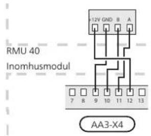
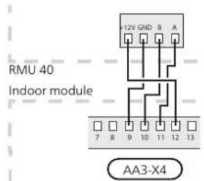
Plinten i RMU 40 ansluts till plint X4:9-12 pa ingangs tet (AA3) i inomhusmodulen.
Installation possibilities
RMU 40 can be installed in several dierent ways, some of which are shown below.
NOTE
This symbol indicates danger to person or machine.
Caution
This symbol indicates important information about what you should observe when maintaining your installation.
TIP
This symbol indicates tips on how to facilitate using the product.
General
With RMU 40 you can control and monitor your NIBE heat pump/indoor module from another room in the house.
Compatible products
F1145
F730
F1155
F750
F1245
VVM 225
F1255
VVM 310
F1345
VVM 320
F1355
VVM 325
F370
VVM 500
F470
SMO 40
Contents
RMU 401
Plastic spacer1
Screws2
Room sensor
1.
RMU 40 contains a room sensor with the same function as that supplied with the heat pump/indoor module (BT50).
This makes it possible to select which room sensor the heat pump/indoor module will use for display and control of the room temperature.

Caution
If both a room sensor (RTS 40) and a room unit are installed in the same climate system only the temperature from RTS 40 is used for display, control and logging.
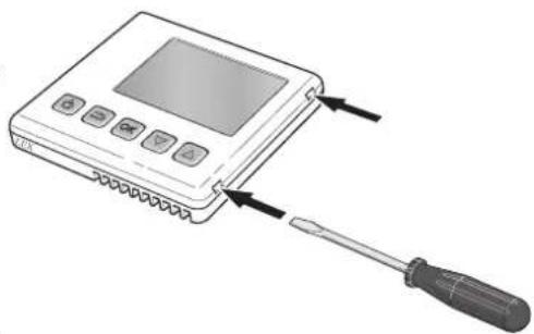
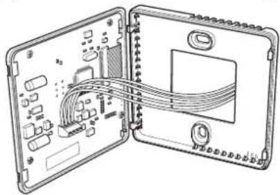
Open RMU 40 by inserting a screwdriver in one of the 4mm wide gaps in the edge. Press the screwdriver straight in to open the clip. Repeat for the other three clips.
The room temperature sensor has up to three functions: 2.
- Show current room temperature in the heat pump/indoor module display.
- Option of changing the room temperature in ^ C
- Makes it possible to change/stabilise the room temperature.
Install the sensor in a neutral position where the set temperature is required. A suitable location is on a free inner wall in a hall approx. 1,5m above the oor. It is important that the sensor is not obstructed from measuring the correct room temperature by being located, for example, in a recess, between shelves, behind a curtain, above or close to a heat source, in a draft from an external door or in direct sunlight. Closed radiator thermostats can also cause problems.
If the sensor is to be used to change the room temp ature in ^ C and/or to rene/stabilise the room tem- 3. perature, the sensor must be activated in the heat pump/indoor module menu 1.9.4.

Caution
If the room sensor is used in a room with underoor heating, it should only have an indicative function, not control of the room temperature.
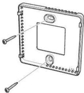
Without plastic spacer: Place the rear panel in front of the apparatus box and screw to the wall.
With plastic spacer: Screw the plastic spacer into the wall. Then screw the the rear panel into the plastic spacer with the two screws supplied.
Connect according to section "Electrical connection".
Installing
RMU 40 cannot be installed directly against a wall because the connection terminal protrudes from the reverse.
Install RMU 40 either in a spare apparatus box or on the plastic spacer supplied.
If you want to use the room temperature sensor in RMU 40 the position of the room unit is important. See section "Room sensor".
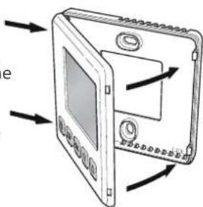
Angle the front panel approx. 30^ and secure the two clips on one side. Then close the unit and secure the two clips on the other side.
Electrical connection
NOTE
All electrical connections must be carried out by an authorised electrician.
Electrical installation and wiring must be carried out in accordance with the stipulations in force. The climate unit must not be powered when installing RMU 40.
NOTE
All electrical connections must be carried out by an authorised electrician.
Electrical installation and wiring must be carried out in accordance with the stipulations in force.
The climate unit must not be powered when installing RMU 40.
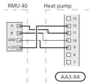
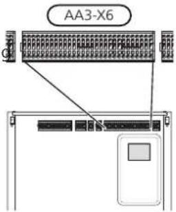
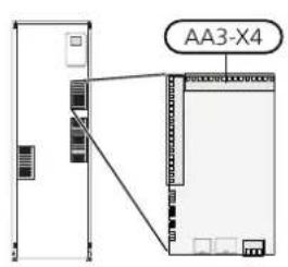
F1145, F1155
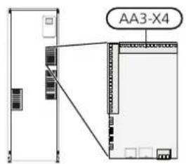
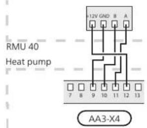
The terminal block in RMU 40 is connected to terminal block X4:9-12 on the input card (AA3) in the heat pump.
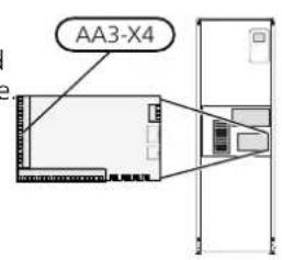
F1245, F1255
The terminal block in RMU 40 is connected to terminal block X4:9-12 on the input card (AA3) in the heat pump.
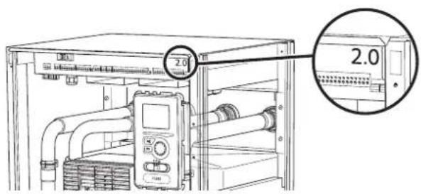
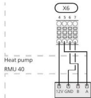
F1345 has direent electrical connection versions depending on when the heat pump was manufactured. To check which electrical connection applies to your F1345, check the designation "2.0" visible above the right hand side of the terminal block as illustrated.
F1345 without 2.0
The terminal block in RMU 40 is connected to terminal block X6:4-7 in the heat pump.
Connecting communication
Use cable type LiYY, EKKX or similar for the following connections.
F1345 with 2.0, F1355
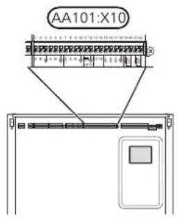
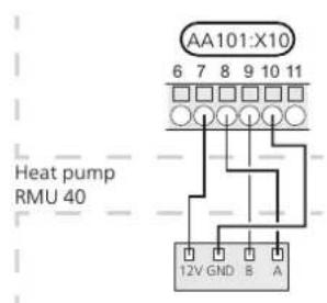
SMO 40
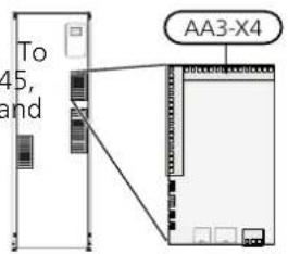
The terminal block in RMU 40 is connected to terminHe terminal block in RMU 40 is connected to terminal block AA101-X10:7-10 in the heat pump. block X4:9-12 on the input board (AA3) on SMO 40.

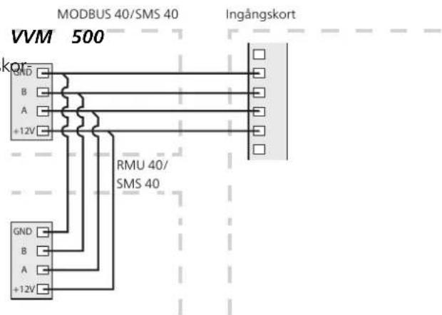
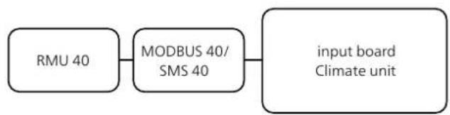
RMU 40 together with MODBUS 40 and SMS 40
If RMU 40 is to be connected with SMS 40 or MODBUS 40, one of these must be the rst unit connected to
The terminal block in RMU 40 is connected to termintake climate unit's terminal block.
block X4:9-12 on the input card (AA3) in the heat ptnction to and from SMS 40/MODBUS 40 occurs in terminal block AA9:X1.
No more than two units can be connected to the climate unit.
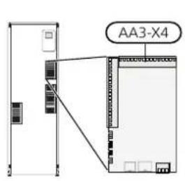
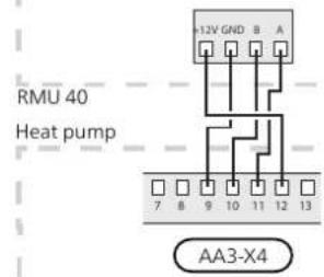
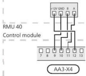
VMM 225, VMM 310, VMM 320, VMM 325,
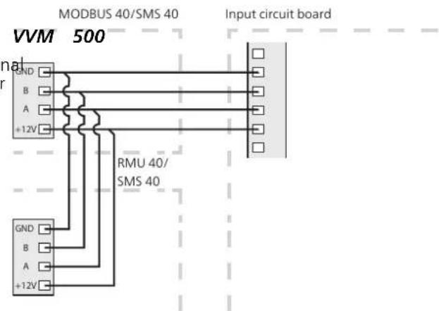
The terminal block in RMU 40 is connected to termin block X4:9-12 on the input card (AA3) in the indoor module.
Program settings
Control - Introduction
- Hold the back button in RMU 40 for 7 seconds access the menu "service settings".
Room unit
- Enter the menu and select which climate system RMU 40 should be connected to.
- Start the heat pump/indoor module, go to menu "system settings" (5.2) and activate RMU 40 for the climate system you want to control with the room unit.
- If you want the heat pump/indoor module to use the room sensor to control the temperature, set it in menu "room sensor settings" (1.9.4). If an external room sensor (BT50) is installed, this will be used. Otherwise the room sensor in RMU 40 is used.
NOTE
The software in the heat pump/indoor module must be version 1199 or higher to work with RMU 40.
A Display
Instructions, settings and operational information are shown on the display.
B Stand-by button
RMU 40 can be switched tostand-by mode using the standby button. The heat pump/indoor module operation is not aected by pressing the button.
C Back button
The back button is used to:
go back to the previous menu.
- change a setting that has not been conrrmed.
D OK button
The OK button is used to:
- conrm selections of sub menus/options/set values.
F Up and down buttons
With the up and down buttons you can:
- scroll in menus and between options.
increase and decrease the values.
Menu system
Selecting options
When RMU 40 is started you come to the information menu. Basic information about the heat pump/indoor module status is shown here. The indoor temperature is displayed in relation to the selected climate system.
In an options menu the current selected option is indicated by a green tick.
To select another option:
- Mark the applicable option using the up or down button. One of the options is pre-selected (white).
- Press the OK button to confirm the selected option. The selected option has a green tick.
Press any button to go to the main menu.
The information menu shows:
on starting.
Setting a value
- when the back button in the main menu is pressed FO set a value:
after 15 minutes of inactivity.
In the event of an alarm a symbol is shown at the top edge of the display together with the alarm's number. Go to the your heat pump/indoor module to get more information.
- Mark the value you want to set using the top up or down button.
Press the OK button. The background of the value becomes green, which means that you have accessed the setting mode.
Operation
To move the cursor, press the up or down button. The marked position is brighter and/or has a turned up tab.
Press the up button to increase the value or the down button to reduce the value.
Selecting menu
To advance in the menu system select a sub-menu by marking it by using the up and down buttons and then pressing the OK button.
- Press the OK button to confirm the value you have set. To undo and return to the original value, press the back button.
Control - Menus
Main menu
Menu 1 - temperature
Sub-menus
Status information for the relevant menu can be found on the display to the right of the sub-menus.
Setting the temperature for the climate system. The status information shows the set value for the climate system.
Activation of temporary increase in the hot water temperature. Status information displays "off" or what length of time of the temporary temperature increase remains.
Setting the fan speed. The status information shows the selected setting. This menu is only displayed for the exhaust air heat pumps and ground source heat pumps with the exhaust air module accessory.
Activation of manual or automatic operating mode. The status information shows the selected operating mode.
Setting which climate system is to be controlled by the room unit. Hold the back button in for 7 seconds to access the Service menu.
If the house has several climate systems, this is indicated on the display by a thermometer for each system.
Setting the temperature (without room sensors activated):
Setting range: -10 to +10
The display shows the set values for heating (curve offset). To increase or reduce the indoor temperature, increase or reduce the value on the display.
Use the arrow buttons to set a new value. Confirm the new setting by pressing the OK button.
The number of steps the value has to be changed to achieve a degree change of the indoor temperature depends on the heating unit. One step for under floor heating whilst radiators may require three.
Setting the desired value. The new value is shown on the right-hand side of the symbol in the display.
Set the temperature (with room sensors installed and activated):
Setting range: 5 - 30^
The value in the display appears as a temperature in ^ C if the heating system is controlled by a room sensor.
To change the room temperature, use the arrow buttons to set the desired temperature in the display. Confirm the new setting by pressing the OK button. The new temperature is shown on the right-hand side of the symbol in the display.
Caution
An increase in the room temperature can be slowed by the thermostats for the radiators or under floor heating. Therefore, open the thermostat valves fully, except in those rooms where a cooler temperature is required, e.g. bedrooms.
TIP
Wait 24 hours before making a new setting, so that the room temperature has time to stabilise.
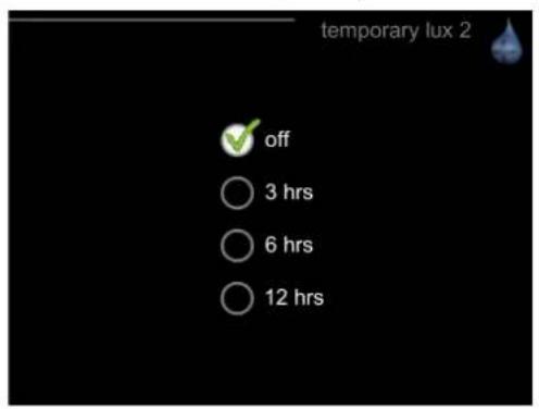
Menu 2 - temporary lux
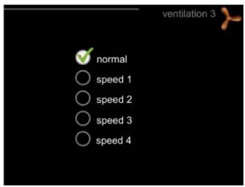
Menu 3 - ventilation
Setting range: 3, 6 and 12 hours, as well as mode "setting range: normal and speed 1-4
When hot water requirement has temporarily increase, this menu can be used to select an increase in the h water temperature to lux mode for a selectable time.

Caution
If comfort mode "luxury" is selected in the pump/indoor module menu 2.2, no further crease can be carried out.
The function is activated immediately when a time is selected and conrrmed using the OK button. The to the right displays the remaining time at the sel setting.
When the time has run out the menu returns to "from" mode.
Select "o" to switch o temporary lu:

Caution
This menu is only displayed for the exhaust air heat pumps and ground source heat pumps with the exhaust air module accessory (FLM).
heat in-The ventilation in the accommodation can be temporarily increased or reduced here.
When you have selected a new speed a clock starts a count down. When the time has counted down the ventilation speed returns to the normal setting.
necessary, the various return times can be changed in the heat pump menu 1.9.6.
Menu 4 - op. mode
op. mode
Setting range: auto, manual, add. heat only
functions
Setting range: addition, heating, cooling
The heat pump/indoor module operating mode is usually set to "auto". It is also possible to set the heat pump/ indoor module to "add. heat only", when only additional heat is used, or "manual" and then select what functions are to be permitted.
Change the operating mode by marking the desired mode and pressing the OK button. To select selectable functions that are permitted or not, mark the function using the arrow buttons and press the OK button.
enu 5 - SERVICE
Operating mode auto
In this operating mode you cannot select which functions are to be permitted because it is handled automatically by the heat pump/indoor module.
Operating mode manual
In this operating mode you can select what functions are permitted.
Operating mode add. heat only
Caution
Here you set which climate system the room unit should be connected to. Conrm the setting using the OK but
If you choose mode "add. heat only" the comton.
pressor is deselected and there is a higher ophe menu displays which product is connected, and the costing cost.
In this operating mode the compressor in the heat pump is not active and only additional heat is used.
Functions
"addition" is what helps the compressor to heat the accommodation and/or the hot water when it cannot manage the whole requirement alone.
"heating" means that you get heat in the accommodation. You can deselect the function when you do not wish to have heating running.
"cooling" means that you get cooling in the accommodation in hot weather. You can deselect the function when you do not wish to have the cooling running. This alternative requires an accessory for cooling or if the heat pump has a built in function for cooling.
Caution
The climate system must also be activated in the heat pump/indoor module menu 5.2. Activate all climate systems you want to control from RMU 40.
Manage alarm
In the event of an alarm a symbol is shown at the top edge of the display together with the alarm's number. Go to the your heat pump/indoor module to get more information.
In the other menus the alarm symbol is shown in the bottom right hand corner.
Troubleshooting
Communication error
- Check that the settings in RMU 40 menu 5 and heat pump/indoor module menu 5.2 agree.
- Check the cable connection between RMU 40 and heat pump/indoor module.
Display extinguished
-
Check the cable connection between RMU 40 and heat pump/indoor module.
-
Check that the unit is not in stand-by mode.
Technical data
Technical specifications
C
| RMU 40 | ||
| Plastic spacer WxHxD | mm | 85x85x35 |
| Dimensions WxHxD | mm | 85x85x14 |
| Rated voltage | 12 VDC 40 mA(supplied from the heat pump/indoor module) | |
| Part No. | 067 064 | |
Deutsch
VMM 225, VMM 310, VMM 320, VMM 325, VMM 5
VMM 225, VMM 310, VMM 320, VMM 325,
VMM 225, VMM 310, VMM 320, VMM 325,
Instelbereik: addition, heating, cooling