X370M Pro4F - Motherboard ASROCK - Free user manual and instructions
Find the device manual for free X370M Pro4F ASROCK in PDF.
Download the instructions for your Motherboard in PDF format for free! Find your manual X370M Pro4F - ASROCK and take your electronic device back in hand. On this page are published all the documents necessary for the use of your device. X370M Pro4F by ASROCK.
USER MANUAL X370M Pro4F ASROCK
Version 1.1 Published October 2020 Copyright©2020 ASRock INC. All rights reserved. Copyright Notice: No part of this documentation may be reproduced, transcribed, transmitted, or translated in any language, in any form or by any means, except duplication of documentation by the purchaser for backup purpose, without written consent of ASRock Inc. Products and corporate names appearing in this documentation may or may not be registered trademarks or copyrights of their respective companies, and are used only for identication or explanation and to the owners’ benet, without intent to infringe. Disclaimer: Specications and information contained in this documentation are furnished for informational use only and subject to change without notice, and should not be constructed as a commitment by ASRock. ASRock assumes no responsibility for any errors or omissions that may appear in this documentation. With respect to the contents of this documentation, ASRock does not provide warranty of any kind, either expressed or implied, including but not limited to the implied warranties or conditions of merchantability or tness for a particular purpose. In no event shall ASRock, its directors, ocers, employees, or agents be liable for any indirect, special, incidental, or consequential damages (including damages for loss of prots, loss of business, loss of data, interruption of business and the like), even if ASRock has been advised of the possibility of such damages arising from any defect or error in the documentation or product. is device complies with Part 15 of the FCC Rules. Operation is subject to the following two conditions: (1) this device may not cause harmful interference, and (2) this device must accept any interference received, including interference that may cause undesired operation.
CALIFORNIA, USA ONLY
e Lithium battery adopted on this motherboard contains Perchlorate, a toxic substance controlled in Perchlorate Best Management Practices (BMP) regulations passed by the California Legislature. When you discard the Lithium battery in California, USA, please follow the related regulations in advance. “Perchlorate Material-special handling may apply, see www.dtsc.ca.gov/hazardouswaste/ perchlorate” ASRock Website: http://www.asrock.comAUSTRALIA ONLY Our goods come with guarantees that cannot be excluded under the Australian Consumer Law. You are entitled to a replacement or refund for a major failure and compensation for any other reasonably foreseeable loss or damage caused by our goods. You are also entitled to have the goods repaired or replaced if the goods fail to be of acceptable quality and the failure does not amount to a major failure. If you require assistance please call ASRock Tel : +886-2-28965588 ext.123 (Standard International call charges apply) e terms HDMI® and HDMI High-Denition Multimedia Interface, and the HDMI logo are trademarks or registered trademarks of HDMI Licensing LLC in the United States and other countries.1 English X370M Pro4-F Motherboard LayoutEnglish
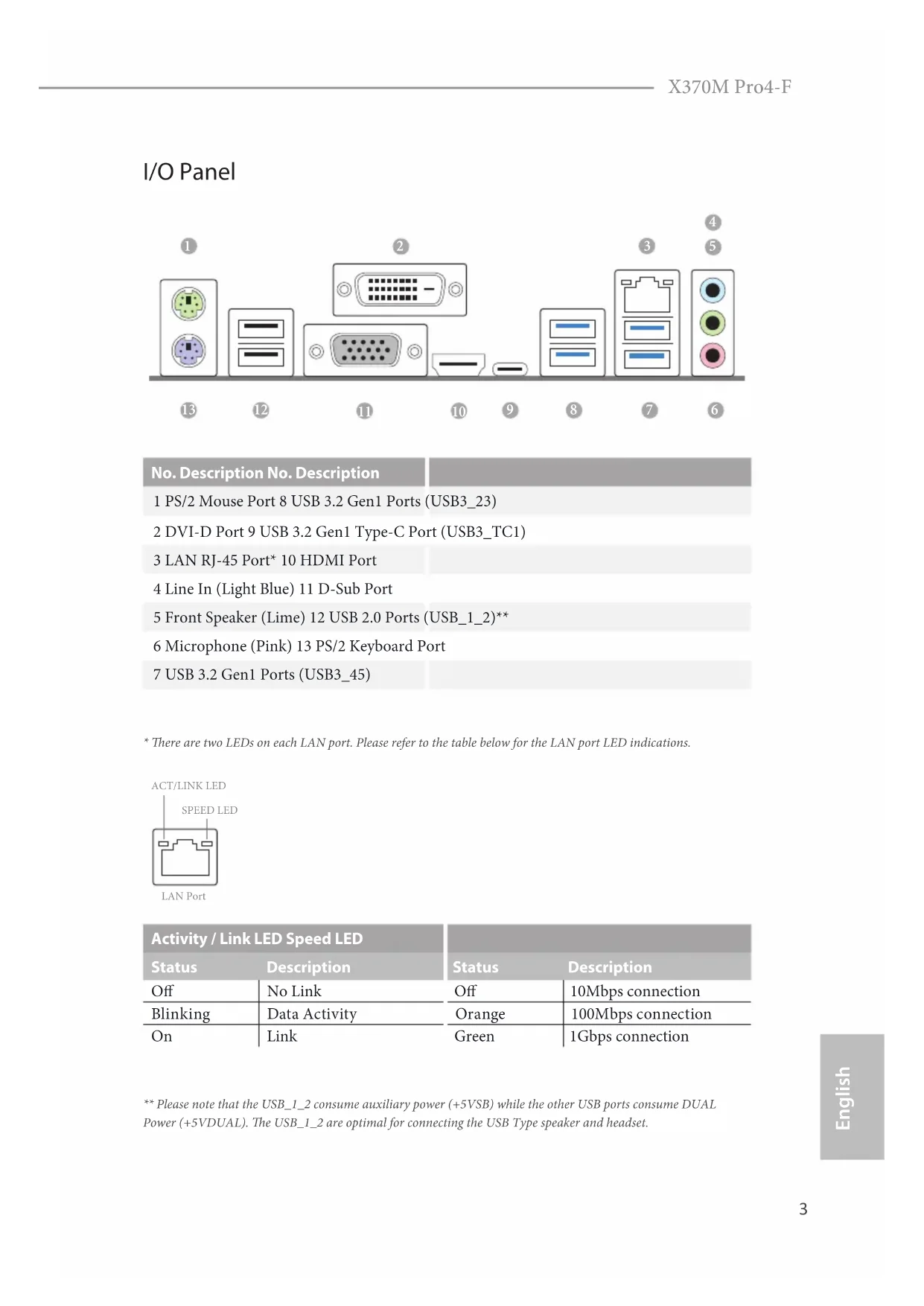
- ere are two LEDs on each LAN port. Please refer to the table below for the LAN port LED indications. Activity / Link LED Speed LED Status Description Status Description O No Link O 10Mbps connection Blinking Data Activity Orange 100Mbps connection On Link Green 1Gbps connection ACT/LINK LEDSPEED LEDLAN Port
** Please note that the USB_1_2 consume auxiliary power (+5VSB) while the other USB ports consume DUAL Power (+5VDUAL). e USB_1_2 are optimal for connecting the USB Type speaker and headset.English
ank you for purchasing ASRock X370M Pro4-F motherboard, a reliable motherboard produced under ASRock’s consistently stringent quality control. It delivers excellent performance with robust design conforming to ASRock’s commitment to quality and endurance.
1 x I/O Panel Shield
2 x Screws for M.2 Sockets (Optional) Because the motherboard specications and the BIOS soware might be updated, the content of this manual will be subject to change without notice. In case any modica-tions of this manual occur, the updated version will be available on ASRock’s website without further notice. If you require technical support related to this motherboard, please visit our website for specic information about the model you are using. You may nd the latest VGA cards and CPU support list on ASRock’s website as well. ASRock website http://www.asrock.com.5 English X370M Pro4-F
Solid Capacitor design CPU
Supports AMD Socket AM4 A-Series APUs (Bristol Ridge) and Ryzen Series CPUs (Matisse, Picasso, Summit Ridge, Raven Ridge and Pinnacle Ridge)
9 Power Phase design Chipset
Dual Channel DDR4 Memory Technology
- For Ryzen Series CPUs (Picasso and Raven Ridge), ECC is only supported with PRO CPUs.
- Please refer to Memory Support List on ASRock’s website for more information. (http://www.asrock.com/)
- Please refer to page 22 for the table for AMD non-XMP mem- ory frequency support. For more details, please refer to the QVL on ASRock’s website.
Expansion Slot AMD Ryzen series CPUs (Matisse, Summit Ridge and Pinnacle Ridge)
- Supports NVMe SSD as boot disks
Integrated AMD Radeon
Vega Series Graphics in Ryzen Series APU*
Integrated AMD Radeon
- Actual support may vary by CPU
Shared memory default 2GB. Max Shared memory supports up to 16GB.
- e Max shared memory 16GB requires 32GB system memory installed.
Supports Triple Monitor
Supports HDMI 1.4 with max. resolution up to 4K x 2K (4096x2160) @ 24Hz / (3840x2160) @ 30Hz
Supports DVI-D with max. resolution up to 1920x1200 @ 60Hz
Supports D-Sub with max. resolution up to 1920x1200 @ 60Hz
Supports Auto Lip Sync, Deep Color (12bpc), xvYCC and HBR (High Bit Rate Audio) with HDMI 1.4 Port (Compliant HDMI monitor is required)
Supports HDCP 1.4 with DVI-D and HDMI 1.4 Ports
Supports Full HD 1080p Blu-ray (BD) playback with DVI-D and HDMI 1.4 Ports7 English X370M Pro4-F Audio
7.1 CH HD Audio with Content Protection (Realtek ALC892
Supports Surge Protection
Supports Wake-On-LAN
Supports Lightning/ESD Protection
Supports LAN Cable Detection
Supports Energy Ecient Ethernet 802.3az
Supports PXE Rear Panel I/O
2 x USB 2.0 Ports (Supports ESD Protection)
1 x USB 3.2 Gen1 Type-C Port (Supports ESD Protection)
4 x USB 3.2 Gen1 Ports (Supports ESD Protection)
1 x RJ-45 LAN Port with LED (ACT/LINK LED and SPEED LED)
HD Audio Jacks: Line in / Front Speaker / Microphone Storage
4 x SATA3 6.0 Gb/s Connectors, support RAID (RAID 0, RAID 1 and RAID 10), NCQ, AHCI and Hot Plug*
- M2_2 and SATA3_3 share lanes. If either one of them is in use, the other one will be disabled.
1 x Ultra M.2 Socket (M2_1), supports M Key type 2242/2260/2280 M.2 PCI Express module up to Gen3 x4 (32 Gb/s) (with Matisse, Picasso, Summit Ridge, Raven Ridge and Pinnacle Ridge) or Gen3 x2 (16 Gb/s) (with A-Series APU and Athlon series APU)** ** Supports NVMe SSD as boot disks ** Supports ASRock U.2 Kit
1 x Power LED and Speaker Header
- Supports in total up to 12V/3A, 36W LED Strip
- Supports in total up to 5V/3A, 15W LED Strip
- e AMD Fan LED Header supports LED strips of maximum load of 3A (36W) and length up to 2.5M.
1 x CPU Fan Connector (4-pin)
- e CPU Fan Connector supports the CPU fan of maximum 1A (12W) fan power.
- CHA_FAN1 can auto detect if 3-pin or 4-pin fan is in use.
1 x Front Panel Audio Connector
2 x USB 2.0 Headers (Support 4 USB 2.0 ports) (Supports ESD Protection)
1 x USB 3.2 Gen1 Header (Supports 2 USB 3.2 Gen1 ports) (Supports ESD Protection) BIOS Feature
AMI UEFI Legal BIOS with multilingual GUI support
Supports “Plug and Play”
ACPI 5.1 compliance wake up events
DRAM Voltage multi-adjustment Hardware Monitor
CPU/Chassis temperature sensing
CPU/Chassis Quiet Fan
CPU/Chassis Fan multi-speed control
ErP/EuP ready (ErP/EuP ready power supply is required)
- For detailed product information, please visit our website: http://www.asrock.com Please realize that there is a certain risk involved with overclocking, including adjust- ing the setting in the BIOS, applying Untied Overclocking Technology, or using third- party overclocking tools. Overclocking may aect your system’s stability, or even cause damage to the components and devices of your system. It should be done at your own risk and expense. We are not responsible for possible damage caused by overclocking.English
is is a Micro ATX form factor motherboard. Before you install the motherboard, study the conguration of your chassis to ensure that the motherboard ts into it. Pre-installation Precautions Take note of the following precautions before you install motherboard components or change any motherboard settings.
Make sure to unplug the power cord before installing or removing the motherboard. Failure to do so may cause physical injuries to you and damages to motherboard components.
In order to avoid damage from static electricity to the motherboard’s components, NEVER place your motherboard directly on a carpet. Also remember to use a grounded wrist strap or touch a safety grounded object before you handle the components.
Hold components by the edges and do not touch the ICs.
Whenever you uninstall any components, place them on a grounded anti-static pad or in the bag that comes with the components.
When placing screws to secure the motherboard to the chassis, please do not over- tighten the screws! Doing so may damage the motherboard.
2.1 Installing the CPU
Unplug all power cables before installing the CPU.
2.2 Installing the CPU Fan and Heatsink
Aer you install the CPU into this motherboard, it is necessary to install a larger heatsink and cooling fan to dissipate heat. You also need to spray thermal grease between the CPU and the heatsink to improve heat dissipation. Make sure that the CPU and the heatsink are securely fastened and in good contact with each other. Installing the CPU Box Cooler SR1 Please turn o the power or remove the power cord before changing a CPU or heatsink.
English X370M Pro4-F 4-pin FAN cable RGB LED Cable +12V *e diagram shown here are for reference only. Please refer to page 32 for the orientation of AMD Fan LED Header (AMD_FAN_LED1).
CPU_FAN1 4-pin FAN cable21 English X370M Pro4-F Please note that only one cable should be used at a time in this step. If you select AMD_FAN_LED1, please install ASRock utility "ASRock Polychrome RGB". If you select USB connector, please install AMD utility "SR3 Settings Soware". *e diagram shown here are for reference only. Please refer to page 32 for the orientation of AMD Fan LED Header (AMD_FAN_LED1) and page 29 for the orientation of AMD LED Fan USB Header (USB_7).
is motherboard provides four 288-pin DDR4 (Double Data Rate 4) DIMM slots, and supports Dual Channel Memory Technology. AMD non-XMP Memory Frequency Support A-Series APUs (Bristol Ridge): Ryzen Series CPUs (Matisse):
1. For dual channel conguration, you always need to install identical (the same
brand, speed, size and chip-type) DDR4 DIMM pairs.
2. It is unable to activate Dual Channel Memory Technology with only one or three
memory module installed.
3. It is not allowed to install a DDR, DDR2 or DDR3 memory module into a DDR4
ere are 3 PCI Express slots on the motherboard. PCIe slots: PCIE1 (PCIe 2.0 x1 slot) is used for PCI Express x1 lane width cards. PCIE2 (PCIe 3.0 x16 slot) is used for PCI Express x16 lane width graphics cards. PCIE3 (PCIe 2.0 x16 slot) is used for PCI Express x4 lane width graphics cards. PCIe Slot Congurations Before installing an expansion card, please make sure that the power supply is switched o or the power cord is unplugged. Please read the documentation of the expansion card and make necessary hardware settings for the card before you start the installation. PCIe Slot PCIE1 PCIE2 PCIE3 A-Series APUs (Bristol Ridge) x1 8 x4 Ryzen Series CPUs (Matisse) x1 x16 x4 Ryzen Series CPUs (Pinnacle Ridge) x1 x16 x4 Ryzen Series CPUs (Summit Ridge) x1 x16 x4 Ryzen Series CPUs (Picasso) x1 x8 x4 Ryzen Series CPUs (Raven Ridge) x1 x8 x4 AMD Athlon Series CPUs x1 x4 x427 English X370M Pro4-F
e illustration shows how jumpers are setup. When the jumper cap is placed on the pins, the jumper is “Short”. If no jumper cap is placed on the pins, the jumper is “Open”. Clear CMOS Jumper (CLRCMOS1) (see p.1, No. 18) Short: Clear CMOS Open: Default CLRCMOS1 allows you to clear the data in CMOS. To clear and reset the system parameters to default setup, please turn o the computer and unplug the power cord from the power supply. Aer waiting for 15 seconds, use a jumper cap to short the pins on CLRCMOS1 for 5 seconds. However, please do not clear the CMOS right aer you update the BIOS. If you need to clear the CMOS when you just nish updating the BIOS, you must boot up the system rst, and then shut it down before you do the clear-CMOS action. Please be noted that the password, date, time, and user default prole will be cleared only if the CMOS battery is removed. Please remember to remove the jumper cap aer clearing the CMOS. 2-pin JumperEnglish
2.6 Onboard Headers and Connectors
System Panel Header (9-pin PANEL1) (see p.1, No. 13) Connect the power switch, reset switch and system status indicator on the chassis to this header according to the pin assignments below. Note the positive and negative pins before connecting the cables. PWRBTN (Power Switch): Connect to the power switch on the chassis front panel. You may congure the way to turn o your system using the power switch. RESET (Reset Switch): Connect to the reset switch on the chassis front panel. Press the reset switch to restart the computer if the computer freezes and fails to perform a normal restart. PLED (System Power LED): Connect to the power status indicator on the chassis front panel. e LED is on when the system is operating. e LED keeps blinking when the system is in S3 sleep state. e LED is o when the system is in S4 sleep state or powered o (S5). HDLED (Hard Drive Activity LED): Connect to the hard drive activity LED on the chassis front panel. e LED is on when the hard drive is reading or writing data. e front panel design may dier by chassis. A front panel module mainly consists of power switch, reset switch, power LED, hard drive activity LED, speaker and etc. When connecting your chassis front panel module to this header, make sure the wire assignments and the pin assignments are matched correctly. Onboard headers and connectors are NOT jumpers. Do NOT place jumper caps over these headers and connectors. Placing jumper caps over the headers and connectors will cause permanent damage to the motherboard. GND R ESET#P WRBTN#P LED-P LED+ GND
GND29 English X370M Pro4-F Power LED and Speaker Header (7-pin SPK_PLED1) (see p.1, No. 14) Please connect the chassis power LED and the chassis speaker to this header. Serial ATA3 Connectors (SATA3_1: see p.1, No. 12) (Upper) (SATA3_2: see p.1, No. 11) (Lower) (SATA3_3: see p.1, No. 9) (Upper) (SATA3_4: see p.1, No. 10) (Lower) ese four SATA3 connectors support SATA data cables for internal storage devices with up to
6.0 Gb/s data transfer rate.
- M2_2 and SATA3_3 share lanes. If either one of them is in use, the other one will be disabled. AMD LED Fan USB Header (4-pin USB_7) (see p.1, No. 8) is header is used for connecting the USB connector on the AMD SR3 Heatsink. USB 2.0 Headers (9-pin USB_3_4) (see p.1, No. 16) (9-pin USB_5_6) (see p.1, No. 17) ere are two headers on this motherboard. Each USB 2.0 header can support two ports.
1. High Denition Audio supports Jack Sensing, but the panel wire on the chassis must
support HDA to function correctly. Please follow the instructions in our manual and chassis manual to install your system.
2. If you use an AC’97 audio panel, please install it to the front panel audio header by
the steps below: A. Connect Mic_IN (MIC) to MIC2_L. B. Connect Audio_R (RIN) to OUT2_R and Audio_L (LIN) to OUT2_L. C. Connect Ground (GND) to Ground (GND). D. MIC_RET and OUT_RET are for the HD audio panel only. You don’t need to connect them for the AC’97 audio panel. E. To activate the front mic, go to the “FrontMic” Tab in the Realtek Control panel and adjust “Recording Volume”. USB 3.2 Gen1 Header (19-pin USB3_67) (see p.1, No. 7) ere is one header on this motherboard. Each USB 3.2 Gen1 header can support two ports. Front Panel Audio Header (9-pin HD_AUDIO1) (see p.1, No. 23) is header is for connecting audio devices to the front audio panel. Chassis Fan Connectors (4-pin CHA_FAN1) (see p.1, No. 24) (3-pin CHA_FAN2) (see p.1, No. 15) Please connect fan cables to the fan connectors and match the black wire to the ground pin.
ATX 12V Power Connector (8-pin ATX12V1) (see p.1, No. 1) is motherboard provides a 8-pin ATX 12V power connector. To use a 4-pin ATX power supply, please plug it along Pin 1 and Pin 5. Serial Port Header (9-pin COM1) (see p.1, No. 19) is COM1 header supports a serial port module. TPM Header (17-pin TPMS1) (see p.1, No. 20) is connector supports Trusted Platform Module (TPM) system, which can securely store keys, digital certicates, passwords, and data. A TPM system also helps enhance network security, protects digital identities, and ensures platform integrity.
CCTS#1RRTS#1DDSR#1DDTR#1RRXD1
RGB LED Header (4-pin RGB_HEADER1) (see p.1, No. 21) RGB LED header is used to con- nect RGB LED extension cable which allows users to choose from various LED lighting ef- fects. Caution: Never install the RGB LED cable in the wrong orienta- tion; otherwise, the cable may be damaged. *Please refer to page 39 for for further instructions on these two headers. Addressable LED Header (3-pin ADDR_LED1) (see p.1, No. 22) is header is used to connect Addressable LED extension cable which allows users to choose from various LED lighting eects. Caution: Never install the Addressable LED cable in the wrong orientation; otherwise, the cable may be damaged. *Please refer to page 40 for fur- ther instructions on this header. AMD FAN LED Header (4-pin AMD_FAN_ LED1) (see p.1, No. 5) AMD FAN LED Header is used to connect RGB LED extension cable that comes with AMD heatsink. e cable connection allows users to choose from various LED lighting eects. Caution: Never install the FAN LED cable in the wrong orienta- tion; otherwise, the cable may be damaged. 12V G R B
The M.2, also known as the Next Generation Form Factor (NGFF), is a small size and versatile card edge connector that aims to replace mPCIe and mSATA. The Ultra M.2 Socket (M2_1) supports type 2242/2260/2280 M.2 PCI Express module up to Gen3 x4 (32 Gb/s) (with Matisse, Picasso, Summit Ridge, Raven Ridge and Pinnacle Ridge) or Gen3 x2 (with A-Series APU and Athlon series APU). Installing the M.2_SSD (NGFF) Module Step 1 Prepare a M.2_SSD (NGFF) module and the screw. Step 2 Depending on the PCB type and length of your M.2_SSD (NGFF) module, nd the corresponding nut location to be used. No. 1 2 3 Nut Location A B C PCB Length 4.2cm 6cm 8cm Module Type Type 2242 Type2260 Type 2280
Step 3 Move the stando based on the module type and length. e stando is placed at the nut location C by default. Skip Step 3 and 4 and go straight to Step 5 if you are going to use the default nut. Otherwise, release the stando by hand. Step 4 Peel o the yellow protective lm on the nut to be used. Hand tighten the stando into the desired nut location on the motherboard. Step 5 Gently insert the M.2 (NGFF) SSD module into the M.2 slot. Please be aware that the M.2 (NGFF) SSD module only ts in one orientation. ABC ABC ABC ABC
The M.2, also known as the Next Generation Form Factor (NGFF), is a small size and versatile card edge connector that aims to replace mPCIe and mSATA. e M.2 Socket (M2_2) supports type 2230/2242/2260/2280 M.2 SATA3 6.0 Gb/s module.
- M2_2 and SATA3_3 share lanes. If either one of them is in use, the other one will be disabled. Installing the M.2_SSD (NGFF) Module Step 1 Prepare a M.2_SSD (NGFF) module and the screw.
Step 3 Move the stando based on the module type and length. e stando is placed at the nut location D by default. Skip Step 3 and 4 and go straight to Step 5 if you are going to use the default nut. Otherwise, release the stando by hand. BCD
Step 4 Peel o the yellow protective lm on the nut to be used. Hand tighten the stando into the desired nut location on the motherboard. Step 5 Gently insert the M.2 (NGFF) SSD module into the M.2 slot. Please be aware that the M.2 (NGFF) SSD module only ts in one orientation. ABCD ABCD
ASRock RGB LED is a lighting control utility specically designed for unique individuals with sophisticated tastes to build their own stylish colorful lighting system. Simply by connecting the LED strip, you can customize various lighting schemes and patterns, including Static, Breathing, Strobe, Cycling, Music, Wave and more. Connecting the LED Strip Connect your RGB LED strip to the RGB LED Header
1. Never install the RGB LED cable in the wrong orientation; otherwise, the cable
2. Before installing or removing your RGB LED cable, please power o your system
and unplug the power cord from the power supply. Failure to do so may cause dam- ages to motherboard components.
1. Please note that the RGB LED strips do not come with the package.
2. e RGB LED header supports standard 5050 RGB LED strip (12V/G/R/B), with a
maximum power rating of 3A (12V) and length within 2 meters.
Connecting the Addressable RGB LED Strip Connect your Addressable RGB LED strip to the Addressable LED Header (ADDR_LED1) on the motherboard. ADDR_LED1
1. Never install the RGB LED cable in the wrong orientation; otherwise, the cable
2. Before installing or removing your RGB LED cable, please power o your system
and unplug the power cord from the power supply. Failure to do so may cause dam- ages to motherboard components.
1. Please note that the RGB LED strips do not come with the package.
2. e RGB LED header supports WS2812B addressable RGB LED strip (5V/Data/
GND), with a maximum power rating of 3A (5V) and length within 2 meters. VOUT
CCTS#1RRTS#1DDSR#1DDTR#1RRXD1
Supporto WOL (Wake-On-LAN)
Supporto Energy Ecient Ethernet 802.3az
1 x porta mouse PS/2
Supporta “Plug and Play”
CCTS#1RRTS#1DDSR#1DDTR#1RRXD1
P CICL KP CIRST #LA D 3
CCTS#1RRTS#1DDSR#1DDTR#1RRXD1
CCTS#1RRTS#1DDSR#1DDTR#1RRXD1
CCTS#1RRTS#1DDSR#1DDTR#1RRXD1
CCTS#1RRTS#1DDSR#1DDTR#1RRXD1
S_PWR DWN #SERIR Q #
Kipas Hening CPU/Chassis
Responsible Party Name: ASRock Incorporation Address:13848 Magnolia Ave, Chino, CA91710+1-909-590-8308/+1-909-590-1026 Phone/Fax No: hereby declares that the product
Product Name : Motherboard Model Number : Conforms to the following specications:
FCC Part 15, Subpart B, Unintentional Radiators
Supplementary Information: is device complies with part 15 of the FCC Rules. Operation is subject to the following two conditions: (1) is device may not cause harmful interference, and (2) this device must accept any interference received, including interference that may cause undesired operation. Representative Person’s Name: James Signature : Date : May 12, 2017
For the following equipment:Motherboard(Product Name)X370M Pro4-F / ASRock(Model Designation / Trade Name)ASRock Incorporation(Manufacturer Name)2F., No.37, Sec. 2, Jhongyang S. Rd., Beitou District, Taipei City 112, Taiwan (R.O.C.)(Manufacturer Address)ASRock EUROPE B.V.(Company Name)Bijsterhuizen 1111 6546 AR Nijmegen e Netherlands(Company Address)Person responsible for making this declaration:(Name, Surname)A.V.P(Position / Title)Dec 27, 2019(Date)P/N: 15G062190001AK V1.1 EMC
Directive 2014/30/EU (from April 20th, 2016)
LVD —Directive 2014/35/EU (from April 20th, 2016) EN 60950-1 : 2011+ A2: 2013 ☐
(EU conformity marking)