
ZISTE1100IV - Generator Zipper - Free user manual and instructions
Find the device manual for free ZISTE1100IV Zipper in PDF.
| Product type | Electric generator |
| Brand | Zipper |
| Model | ZISTE1100IV |
| Engine | 4-stroke, unleaded petrol |
| Recommended engine oil | 15W40 |
| Oil capacity | 260 ml |
| Air filter | Cleanable with soapy water |
| Spark plug | Electrode gap 0.6-0.7 mm |
| Use | Outdoor only, flat and hard surface |
| Operating temperature | +5°C to +40°C |
| Maximum humidity | 65 % |
| Storage temperature | -20°C to +55°C |
| Safety | Oil sensor, overload protection, short circuit, high temperature |
| Maintenance | Maintenance plan: oil change, air filter cleaning, spark plug |
| Spare parts | Use original ZIPPER parts |
| Warranty | 2 years DIY use, 1 year professional use |
Frequently Asked Questions - ZISTE1100IV Zipper
User questions about ZISTE1100IV Zipper
0 question about this device. Answer the ones you know or ask your own.
Ask a new question about this device
Download the instructions for your Generator in PDF format for free! Find your manual ZISTE1100IV - Zipper and take your electronic device back in hand. On this page are published all the documents necessary for the use of your device. ZISTE1100IV by Zipper.
USER MANUAL ZISTE1100IV Zipper
ATTENTION: Check Oil (15W40)!
Engine doesn't start with low oil!!
1 INHALT / INDEX
1 INHALT / INDEX 2
10.1 Intended use of the machine....21
10.1.1 Technical Restrictions ......21
10.1.2 Prohibited Use / Forseeable Misuse....21
10.2 User Requirements.... 21
10.3 Safety instructions 22
10.4 Special safety instructions for the operation of the machine 22
10.5 Safety instructions for machines with combustion engine.... 22
10.6 Hazard warnings 23
11 OPERATION 24
11.1 Pre-operation check 24
11.1.1 Check engine oil....24
11.1.2 Check fuel 24
11.2 Operation instructions.... 24
11.3 Operation 25
11.3.1 Start....25
11.3.2 Stop 25
12 MAINTENANCE 26
12.1 Maintenance plan 26
12.2 Cleaning 26
12.3 Engine oil change 27
12.4 Air cleaner 27
12.5 Spark plug 28
12.6 Fuel tank and fuel filter 28
12.7 Transport.... 28
12.8 Storage.... 28
12.9 Disposal....29
13 TROUBLE SHOOTING 29
14 PRÉFACE (FR) 30
15 SÉCURITÉ 31
EN EC-CONFORM - This product complies with the EC-directives.
EN READ THE MANUAL! Read the user and maintenance manual carefully and ge familiar with the controls in order to use the machine correctly and to avoid injuries and machine defects.
EN ATTENTION! Ignoring the safety signs and warnings applied on the machine as well as ignoring the security and operating instructions can cause serious injuries and ever lead to death.
EN Keep safe distance!
EN Danger of Intoxication (CO)! Only use outdoors and far from open windows and vents!
EN Warning of flammable liquids; turn off the engine before filling (gasoline)
EN ATTENTION! For transport, oil has been drained. Fill up with 4-stroke quality motor oil before first operation! Failure to do so will result in permanent engine damage and void guarantee.
ZI-STE1100IV
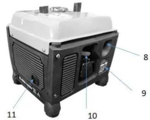
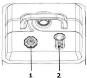
| 1 | Tankverschluss / Tank cap / Bouchon de réservoir / Kapica/poklopac spremnika / Pokrov rezervoarja za gorivo / Tartályzár /Uzávěr nádrže | 7 | Choke-Hebel / choke lever / Levier de préchauffage / Poluga čoka / Ročica za zaug / Szívató kar /Páčka sytiče |
| 2 | Treibstofftank / fuel tank / Réservoir de carburant / Spremnik goriva / Rezervoar za gorivo / Üzemanyagtartály /Palivová nádrž | 8 | Treibstoffhahn / fuel tap / Robinet de carburant / Slavina goriva / Pipa za gorivo / Üzemanyagcsap /Palivový kohout |
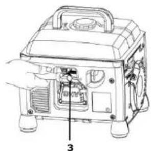
| 3 | EIN-AUS-Hauptschalter / Engine switch / Interrupteur principal / Prekidač za paljenje i gašenje / Glavno stikalo za VKLOP/IZKLOP / BE- KI fő kapcsoló /Hlavní vypínač ZAPNUTO-VYPNUTO | 9 | Treibstoffablassschraube (Vergaser) /Fuel drain port (carburetor) / Ouverture de vidange carburateur essence / Otvor za izlijevanje benzina / Odprtina za izpust bencina (uplinjač) / Benzinlefolyó úszóház porlasztó /Otvor pro vypuštění motorového oleje |
| 4 | Bedienpanel / control panel / Plaque d'identification / Kontrolna ploča / Kontrolna plošča / Kezelőpanel /Ovládací panel | 10 | Zündkerzenstecker / spark plug / Bougie d'allumage / Svjećica / Vtič za vžigalno svečko / Gyertyapipa /Zapalovací svíčka |
| 5 | Luftfilterabdeckung / air cleaner cover / Carter filtre à air / Poklopac pročistača zraka / Pokrov zračnega filtra / Levegőszűrőfedél /Kryt vzduchového filtru | 11 | Auspuff / muffler / Pot d'échappement / Prigušivač / Izpuh / Kipufogó /Výfuk |
| 6 | Startergriff / starter grip / Lanceur de démarrage / Ručka startera / Ročica zaganjalnika / Indítókar /Startovací kabel |
Bedienpanel / control panel / Panneau de commande / Kontrolna ploča / Kontrolna plošča / Kezelőpanel / Ovládací panel
| 1 | Steckdose / Socket / Prise / Utičnica (varijabilna) / Vtičnica (variabilna) / Dugóaljzat (můszakilag eltérő lehet)Zásuvka (technicky variabilní) |
| 2 | Erdungsanschluss /ground terminal / Mise à la terre / Priključak za uzemljenje / Ozemljitveni priključek / Földelési csatlakozásUžěmnění |
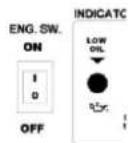
| 3 | EIN-AUS-Hauptschalter / engine switch / Interrupteur / Sklopka/prekidač za paljenje i gašenje / Glavno stikalo za VKLOP-IZKLOP / BE- KI fő kapcsoló / Hlavní vypínač ZAPNUTO-VYPNUTO |
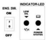
| 4 | Ölkontrollleuchte / oil alarm indicator light / Voyant d’alarme niveau d’huile/ Lampica upozorenja razine ulja / Kontrolna lučka za olje / Motorolajellenőrző-lámpaKontrolka motorového oleje |
| 5 | Ausgangskontrollleuchte / output indicator light / Voyant Output / Lampica upozorenja izlaznog napona / Kontrolna lučka izhodne napetosti / Kimenet-ellenőrzőlámpa / Kontrolka napětí na výstupu |

3.2 Technische Daten / Technical data / Données techniques / Tehnički podaci / Tehnični podatki / Můszaki adatok / Technické údaje
| ZI-STE1100IV | |
| Motortyp / engine type / Type moteur / Tip motora / Tip motorja / Motor tipus /Typ motor | 1-Zylinder 4-Takt |
| Hubraum / displacement / Cylindrée / Zapremina-kapacitet / Prostornina / Hengerürtartalom / Zdvih | 53,5 cm3 |
| Motorleistung / engine power / Puissance moteur / Snaga motora / Moč motorja / Motorteljesítmény / Výkon motoru | 1,3 kW |
| Motordrehzahl / engine speed / Vitesse moteur / Brzina motora / Število vrtljajev motorja / Motorfordulatszám / Otáčky motoru | max. 4800 min-1 |
| Starter / starter / Démarrage / Starter / Zaganjalnik / Indító /Startér | Seilzug /recoil / Lanceur / na poteg vrvi / Kábel /startovací kabel |
| Zündung /ignition / Bougie d'allumage / Paljenje / Vžig / Gyújtás /Zapalování | CDI |
| Laufleistung / operation time / Autonomie / Vrijeme rada / Čas delovanja / Futásteljesítmény /Doba běhu | min. 5,4 h |
| Verbrauch / fuel consumption / Consommation de carburant / Potrošnja goriva / Povprečna poraba / Átlagos fogyasztás/Průměrná spotřeba | 0,77 l/h |
| Treibstoff / fuel / Carburant / Gorivo / Gorivo / Üzemanyag /Palivo | Normalbenzin / unleaded fuel / neosvinčeni bencin / ólommentes benzin /bezolovnatý benzin |
| Tankkapazität / fuel tank capacity / Capacité réservoir de carburant / Kakacitet spremnika goriva / Kapaciteta rezervoarja / Tartály ürtartalma /Objem nádrže | 4,2 l |
| Motoröl / engine oil / Huile moteur / Motorno ulje / Motorno olje / Motorola /Motorový olej | 15W40 |
| Motoröltankkapazität / oil tank capacity / Capacité réservoir d'huile / Kapacitet spremnika ulja / Kapaciteta rezervoarja motornega olja / Motorola/tartály ürtartalma /Objem nádrže motorového oleje | 260 ml |
| Generatordauerleistung / rated output power / Puissance de sortie / Nominalna izlazna snaga generatora / Trajna moč generatorja / Generátor állandó teljesítmény /Trvalý výkon generátoru | 1000 W |
| Max. Leistung / max output / Puissance max. / Maksimalna izlazna snaga / Maksimalna moč generatorja / Max. Teljesítmény /Max. výkon | 1100 W (S2 5min) |
| Schutzklasse / protection class / Classe de protection / Klasa zaštite / Zaščitni razred / Védelmi osztály /Třída ochrany | I |
| Schutzart / protection mode / Mode de protection / Vrsta/mod zaštite / Vrsta zaščite / Védettség /Ochrana | IP23M |
| Ausgangsspannung Steckdose / Output voltage / Prise de courant / Utičnica / Vtičnica / Csatlakozódugó /Zásuvka | 1 x 230 V / 50 Hz |
| Schalldruckpegel / Sound pressure level / Pression sonore / Razina zvučnog tlaka/opterećenje / Nivo zvočnega tlaka / Hangnyomásszint /Hladina akustického tlaku LPA | 74 dB (A) k:1,07 dB(A) |
| Garantierter Schallleistungspegel / guaranteed sound power level / Puissance acoustique garantie / Garantirana razina snage zvuka / Zajamčen nivo zvočne moči / Garantált zajszint /Hladina akustického výkonu LWA | 95 dB(A) |
| Maschinenmaße / machine dimension / Dimension machine / Dimenzije stroja / Mere stroja / A gép méretei / Rozměr | 355 x 324 x 306 mm |
| Gewicht / weight / Poids / Težina / Teža / Súly /Hmotnost | 12,8 kg |
4 VORWORT (DE)

6.3.2 Stoppen

7.7 Transport
7.9 Entsorgung

This manual contains information and important instructions for the installation and correct use of the ZIPPER generators ZI-STE1100IV.
Following the usual commercial name of the machine (see cover) is substituted in this manual with the name "machine".

This manual is part of the product and shall not be stored separately from the product. Save it for later reference and if you let other people use the product, add this instruction manual to the product.
Please read and obey the security instructions!
Due to constant advancements in product design, construction pictures and content may diverse slightly. However, if you discover any errors, inform us please.
Technical specifications are subject to changes!
Please check the product contents immediately after receipt for any eventual transport damage or missing parts.
Claims from transport damage or missing parts must be placed immediately after initial product receipt and unpacking before putting the product into operation.
Please understand that later claims cannot be accepted anymore.
Copyright
© 2018
This document is protected by international copyright law. Any unauthorized duplication, translation or use of pictures, illustrations or text of this manual will be pursued by law.
Court of jurisdiction is the Landesgericht Linz or the competent court for 4707 Schlüsslberg, AUSTRIA.
Customer Support
This section contains information and important notices for safe commissioning and handling of machine.

For your own safety, read these operating instructions carefully before putting the machine into operation. This will enable you to handle the machine safely and prevent misunderstandings as well as possible damage to property and persons. Also observe the symbols and pictograms used as well as the safety instructions and hazard warnings!
10.1 Intended use of the machine
The machine is intended exclusively for the following activities:
This power unit is designed exclusively for operating electric devices whose max. performance is within the specifications for the generator. A higher starting current of inductive loads must be considered. The generator is designed to operate from conventional resistive and inductive loads, such as Lights, electric hand tools (drills, electric chain saws, compressors) determined.
When connecting to stationary systems such as heating, house supply, air conditioning or for the power supply of mobile homes, an electrician and the heating manufacturer must be consulted regarding the connection and grounding.
ZIPPER-MASCHINEN assumes no responsibility or warranty for any other use or use beyond this and for any resulting damage to property or injury.
10.1.1 Technical Restrictions
The machine is intended for use under the following ambient conditions:
Relative humidity: max. 65 %
Temperature (for operation) +5°C bis +40°C
Temperature (for storage and/or transport) -20° C bis +55° C
10.1.2 Prohibited Use / Forseeable Misuse
• Operation of the machine without adequate physical and mental aptitude
- Operating the machine without appropriate knowledge of the operating instructions (machine + motor).
• Changes in the design of the machine
- Operating the machine in wet and rainy conditions
- Operating the machine in a potentially explosive environment
- Operating the machine indoors or in closed areas
• Operation of the machine without functioning or missing guards
- Remove the safety markings attached to the machine.
- Modify, circumvent or disable the safety devices of the machine.
The prohibited/hazardous use or disregard of the information and instructions presented in this manual will result in the voiding of all warranty and damage claims against Zipper Maschinen GmbH.
10.2 User Requirements
The physical and mental suitability as well as knowledge and understanding of the operating instructions are prerequisites for operating the machine. Persons who, because of their physical, sensory or mental abilities or their inexperience or ignorance, are unable to operate the machinery safely must not use it without the supervision or instruction by a responsible person.
Please note that local laws and regulations may determine the minimum age of the operator and restrict the use of this machine!
Put on your personal protective equipment before working on the machine.
Work on electrical components or equipment may only be carried out by a qualified electrician or carried out under the guidance and supervision of a qualified Electrician.
10.3 Safety instructions
In order to avoid malfunctions, damage and health hazards when working with this machine, in addition to the general rules for safe working, the following measures in particular must be observed UNCONDITIONALLY:
- Check that the machine is in perfect condition before each use. Ensure that all guards are in place and working properly and that all nuts, bolts, etc. are securely tightened. Do not take the machine into operation if you notice that parts are missing or damaged!
- Ensure sufficient lighting conditions in the working and surrounding areas of the machine.
- Keep hands and feet away from moving machine parts and always ensure a safe stand when working.
- Ensure that the area to be tamped does not contain any electric cables, gas or water lines which could be damaged by vibration.
- Remove the adjustment tool from the machine before operation.
- Ensure that unauthorised persons maintain a safe distance from the machine and keep children away from the machine.
- The machine may only be operated, serviced or repaired by persons who are familiar with it and who have been informed of the dangers arising during this work.
• Always wear suitable personal protective equipment (eg. ear protection,.., etc.)! - Do not work with the machine if you are tired, not concentrated or under the influence of medication, alcohol or drugs!
- Never operate the unit in the presence of flammable liquids or gases (danger of explosion!).
- Carry out maintenance, adjustment and cleaning work only when the engine is switched off.
- Only use spare parts and accessories recommended by Zipper machines.
10.4 Special safety instructions for the operation of the machine
- Do not use the generator if it is raining, wet or has high humidity. RISK OF ELECTRIC SHOCK. DANGER OF LIFE!.
- Place the generator at least 1m away from buildings and the equipment connected to it.
- Place the generator in a secure, level position. Do not turn, tip or change the generator's position while it is working
10.5 Safety instructions for machines with combustion engine
- Do not touch the engine and/or muffler during operation or immediately after switching off! These areas become hot during operation and can cause burns.
- Do not touch the spark plug connector when the engine is running (electric shock!).
- Do not operate the unit in closed areas or in poorly ventilated rooms unless there is adequate ventilation through exhaust fans or hoses. (Risk of suffocation from carbon monoxide!)
- Do not smoke while the machine is in operation.
- Do not smoke when refuelling the machine.
- Refuel the machine only in a well ventilated area.
- Do not refuel the machine when the engine is running or the machine is still hot.
- Do not refuel the machine near naked flames.
- Do not spill fuel when refuelling.
- Do not crank a gas flooded engine as long as the spark plug is removed- fuel in the cylinder sprays out of the spark plug opening.
- Do not carry out an ignition spark test on engines if the engine is flooded or gas can be smelled. A stray spark could ignite the vapours.
- Do not use fuel to clean machine parts, especially indoors. Vapours from fuels may explode.
- Always keep the area around the muffler free of foreign substances such as leaves, paper, cardboard, etc. A hot muffler could ignite these substances and cause a fire.
- Close the filler cap after refuelling.
- Check the fuel line and tank regularly for leaks and cracks. Do not operate the machine if leaks in the fuel system are known.
- Store fuel only in designated and approved containers.
10.6 Hazard warnings
Despite intended use, certain residual risks remain.
- Risk of burns:
Touching the mufflers, exhaust and other machine components which can be hot after prolonged continuous operation or when the engine is hot cause severe burns.
- Risk of fire and explosion:
Gasoline is highly flammable and explosive under certain conditions.
NEVER refuel fuel or engine oil while the machine is in operation or is hot.
When refueling and at places where fuel is stored not smoke or allow open flames or sparks.
Do not overfill the fuel tank and avoid the spillage of gasoline during refueling. If fuel is spilled make sure the area is completely dry and cleaned before starting the engine.
Make sure that the filler cap is tightly closed again after refueling safely.
- Chemical risks
Never use or refuel a gasoline or diesel engine in a closed area without adequate ventilation.
Carbon monoxide emissions from the internal drive units of the engine can cause in confined spaces through inhalation health effects and death. Therefore use the machine only in well-ventilated rooms or outdoors in operation.
Liquid fuels can cause serious damage on the skin and the environment.
- Risk of electric shock
Direct electrical contact may cause electric shock.
Never touch the unit with wet hands. Provide adequate grounding.
- Hearing damage
A longer stay in the immediate vicinity of the running unit may cause hearing damage.
Wear ear protectors!
Due to the design and construction of the machine, hazardous situations may occur which are identified as follows in these operating instructions:
DANGER

A safety instruction designed in this way indicates an imminently hazardous situation which, if not avoided, will result in death or serious injury.
WARNING

Such a safety instruction indicates a potentially hazardous situation which, if not avoided, may result in serious injury or even death.
CAUTION

A safety instruction designed in this way indicates a potentially hazardous situation which, if not avoided, may result in minor or moderate injury.
NOTICE

A safety note designed in this way indicates a potentially dangerous situation which, if not avoided, may result in property damage.
Irrespective of all safety regulations, their sound common sense and corresponding technical suitability/training are and remain the most important safety factor in the error-free operation of the machine. Safe working depends first and foremost on you!
11 OPERATION
Please check the product contents immediately after receipt for any eventual transport damage or missing parts. Claims from transport damage or missing parts must be placed immediately after initial machine receipt and unpacking before putting the machine into operation. Please understand that later claims cannot be accepted anymore.
11.1 Pre-operation check
11.1.1 Check engine oil
NOTICE

The generator is delivered without engine oil and fuel! Engine oil 15W40 must be filled before first use!

See capture maintenance => engine oil change
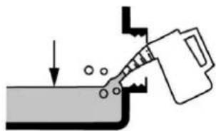
11.1.2 Check fuel
Place the machine on a firm and flat surface.
Open the fuel cap.
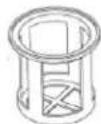
Check the fuel filter.
Never refuel without fuel filter!
Fuel must be unleaded gasoline

11.2 Operation instructions
NOT ICE

- Always place the machine on a firm and flat surface! No turning, tilting or moving during the engine is running
• Always check oil and fuel level before starting - Do not connect the appliance before the unit is running at full speed. Disconnect the appliance before turning the unit off.
- Connected devices must be in perfect condition.
- Keep the cable length to the consumer as short as possible.
11.3 Operation
11.3.1 Start
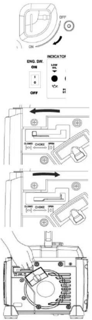
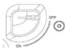
Turn the fuel cock to position „ON“
Switch the ON-OFF switch to position „I“ ON.
At cold start pull the choke to position „CLOSED“.
At worm start (the engine was running and is still warm) pull choke to Position „OPEN“.
If the generator fails to start after 5 attempts, pull choke to position "CLOSED" and try again.
After the engine starts pull the choke to position „OPEN“ after 20 s.
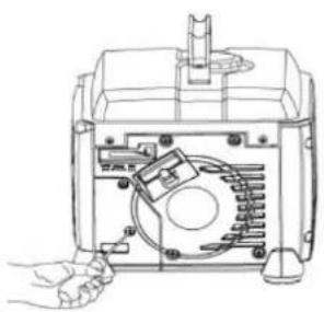
Start the engine with the recoil starter:
Grip the handle and pill the recoil starter.
If the engine does not start, try again.
Normally start: 3-4 attempts
When starting with the recoil starter, the motor may recoil suddenly as it starts up, resulting in hand injuries!

11.3.2 Stop
- In normal circumstances switch off the generator as follows:
Shut down the connected devices and disconnect them from the generator. To cool down let the engine running for a while without any loads.
Switch off the generator by putting the ON-OFF switch to position „0“ OFF
At longer breaks:
To cool down let the engine running for a while without any loads.
Thereafter close the fuel cock by turning to position „OFF“.
The engine runs until the remaining fuel is consumed in the carburetor.
Switch off the generator by putting the ON-OFF switch to position „0“ OFF
- In case of emergency stop the generator directly with the ON-OFF switch


12 MAINTENANCE
WARNING

No cleaning, upkeep, checks or maintenance when machine is running!
Shut off the machine and let it cool down before start servicing!
The machine does not require intense maintenance. However, to ensure a long lifespan, we strongly recommend following the upkeep and maintenance plan.
Repairs must be carried out by specialists! Use original ZIPPER parts only!
NOT ICE

Only a properly maintained equipment may be a satisfactory tool. Care and maintenance deficiencies can cause unpredictable accidents and injuries.
Repairs should be performed only by authorized service centers.
Improper operation may damage the equipment or endanger your safety.
12.1 Maintenance plan
| Servicing period | Before any using | After: 1 month 5 HOO | After: 3 month 25 HOO | After: 6 month 50 HOO | After: 12 month 100 HOO | After: 25 month 250 HOO | |
| Engine oil (15W40) | Inspection | X | |||||
| Change | X | X | |||||
| Air filter | Inspection | X | |||||
| Change | X | ||||||
| Spark plug | Inspection | X | |||||
| Change | X | ||||||
| Fuel tank / fuel filter | Inspection | ||||||
| Change | X | ||||||
Provide appropriate servicing upon the earlier of the following: in the given month or after the specified hours of operation (HOO) have expired.
12.2 Cleaning
- We recommend cleaning the machine immediately after each use.
- Keep all safety devices, air vents and the motor housing free of dirt and dust as far as possible
- Wipe the equipment with a moist cloth and some soft soap or blow it with compressed air at low pressure.
NOTICE

Do not use cleaning agents or solvents; these could attack the plastic parts of the machine!
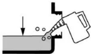
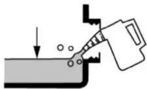
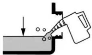
12.3 Engine oil change
NOTICE


Waste oils are toxic and must not be released into the environment! Contact your local authorities for information on proper disposal.
NOT ICE

Drain the used oil quickly and completely while the engine is still warm.
- Unscrew the oil filler cap (3); tilt the machine and let the used oil run into a suitable container.

- Add new engine oil (15W40, 260ml) (2) and close the oil cap.
- Clean it with a rag.
- Put the machine on an even area and start the engine. If there is sufficient oil level the oil-warning sensor (1) will be not activated.
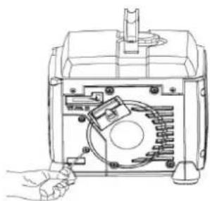
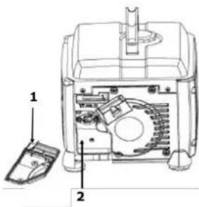
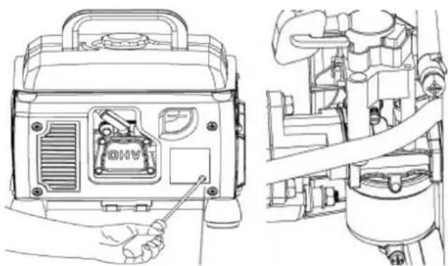
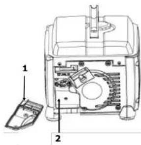
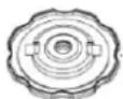
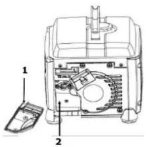
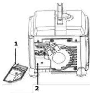
12.4 Air cleaner
- Loosen the screws and remove the air cleaner cover (1)
- Remove the air cleaner (2)
- Clean the air filter with soapy water, then rinse with clear water and let it dry thoroughly before reassembling.
- Reassemble the air cleaner in reverse order
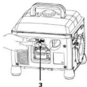
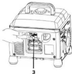
12.5 Spark plug
- Remove the spark plug cap (1).
- Loosen the spark plug (2) using a spark plug socket (3).
- Remove carbon deposits with a copper wire brush.
- Check electrode gap (0,6 -0,7mm)
- Reassemble the spark plug in reverse order
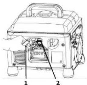
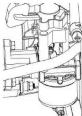
12.6 Fuel tank and fuel filter
- Unscrew the fuel cap (1)
- Remove and clean the fuel filter (2)
- Check the fuel tank
- Replace the fuel filter
12.7 Transport
- Secure the machine to prevent slipping
- Do not let the fuel spill out of the fuel tank.
- When the generator is placed on vehicle, the engine may not run.
- During transport, protect the machine from excessive heat. If longer periods in an enclosed vehicle the fuel may ignite due to overheating.
12.8 Storage
If the machine is stored for longer than 30 days:
- Wait until the engine cools down sufficiently.
- Allow the fuel from the tank into a suitable container and store the drained fuel in a suitable container.
- Clean and dry machine
• Store in a dry, out of reach of children place - Cover the machine well and store it in a dry and clean place.
12.9 Disposal

Do not dispose the machine, machine components fuel and oil in residual waste. Contact your local authorities for information regarding the available disposal options. When you buy at your local dealer for a replacement unit, the latter is obliged to exchange your old.
13 TROUBLE SHOOTING
| Trouble | Possible cause | Solution |
| Engine does not start | Incorrect starting sequence | Observe the correct starting sequence |
| Dirty air cleaner | Clean/replace air cleaner | |
| No fuel supply | Refuel | |
| Fault in the fuel line | Check the fuel line for kinks or damages | |
| Engine flooded. | Screw off, clean and dry the spark plug. Then pull the cranking rope several times and reinstall the spark plug | |
| Spark plug connector not placed on. | Place on the spark plug connector | |
| No ignition spark | Clean/replace spark plugCheck ignition cable | |
| Fuel cock closed | Open fuel cock | |
| Engine oil to few | Check engine oil | |
| Engine starts and is stalled immediately | Incorrect idle adjustment | Contact customer service |
| Machine works with interruptions | Carburetor incorrectly adjusted | Contact customer service |
| Spark plug fouled | Clean/replace spark plugCheck spark plug connector | |
| Oil alarm indicator light flashes | Check oil level | Fill engine oil |
| Oil alarm indicator light glows | To less or no oil | Fill engine oil |
| Output indicator light interval flash 1x | Low voltage protection activated | Engine speed to low |
| Output indicator light interval flash 2x | High temperature protection activated | Cool down the engine |
| Output indicator light interval flash 3x | Overload protection activated | To big loads |
| Output indicator light interval flash 4x | Short circuit protection activated | Check loads |

NOTICE
Should you in necessary repairs not able to properly to perform or you have not the prescribed training for it always attract a workshop to fix the problem.
14 PRÉFACE (FR)
Cher client!

17 ENTRETIEN
ATTENTI ON

17.7 Transport
17.9 Recyclage


NE ULIJEVAJTE GORIVO KADA
RADI!
21.2 Upute za rad
NAP OMENA


22.5 Svjećica

22.6 Spremnik goriva i filtar goriva
• Odvinite kapicu filtra goriva (1)
- Izvadite i očistite filtar goriva (2)
• Provjerite spremnik goriva
- Ponovno vratite filtar goriva

22.7 Transport
22.9 Odlaganje

Ne odlažite stroj niti njegove komponente, kao ni gorivo i ulje, u normalan otpad! Stupite u kontakt s lokalnim nadležnim vlastima vezano uz informacije za opcije odlaganja. Ukoliko kupujete zamjenske dijelove kod lokalnog dobavljača, on je obavezan odlagati stare dijelove/komponente.
23 OTKLANJANJE POTEŠKOĆA I SMETNJI
26.3.2 Zaustavitev
27 VZDRŽEVANJE
OPOZORILO

27.4 Zračni filter
- Odvijte vijake in odstranite pokrov zračnega filtra (1)
- Odstranite zračni filter (2)
- Zračni filter očistite z milnico ali z blagim detergentom in vodo, ga sperite pod čisto vodo in pustite, da se posuši, preden ga ponovno vstavite.
- Ponovno vstavite filter tako, da izvedete iste korake v obratnem vrstnem redu.
27.5 Svečka
• Vtič vžigalne svečke (1) snemite z zasukom.
- Odstranite svečko (2) s ključem za vžigalno svečko (3).
- Preglejte svečko, će je umazana in jo po potrebi očistite z žično krtačo.
- Preverite razmik med elektrodama (0,6 - 0,7mm).
- Ponovno vstavite svečko tako, da izvedete iste korake v obratnem vrstnem redu.

27.6 Rezervoar bencina in filter za bencin
- Odstranite pokrov rezervoarja za gorivo (1)
- Očistite filter (2)
• Preverite rezervoar za gorivo - Ponovno vstavite filter

27.7 Transport
27.9 Odstranjevanje
NE TANKOLJON MÜKÖDÖ GÉP MELLETT


31.3.2 Leállítás

FIGYELEM

32.4 Levegőszűrő
32.5 Gyújtógyertya

32.7 Szállítás
36.2 Provozní pokyny
POKYN


37 ÚDRŽBA
VAROVÁNÍ


37.7 Transport
37.9 Likvidace
(EN) With original ZIPPER spare parts you use parts that are attuned to each other shorten the installation time and elongate your machines lifespan.
IMPORTANT
The installation of other than original spare parts voids the warranty!
So you always have to use original spare parts
When you place a spare parts order please use the service formular you can find in the last chapter of this manual. Always take a note of the machine type, spare parts number and partname. We recommend to copy the spare parts diagram and mark the spare part you need.
You find the order address in the preface of this operation manual.
| # | Description | Qty | # | Description | Qty |
| 1 | engine | 1 | 22 | Cross recessed pan head tapping screws ST6.3x25 | 7 |
| 2 | hexagon nut with flange M10X1.25-8 | 1 | 23 | back panel | 1 |
| 3 | stator | 1 | 24 | air-returning pipe | 1 |
| 4 | radar tube | 3 | 25 | Ignition coil | 1 |
| 5 | Hexagon flange bolts M5x30 | 3 | 26 | back wind scooper | 1 |
| 6 | flywheel | 1 | 27 | supporting tube | 3 |
| 7 | fan blade | 1 | 28 | left panel | 1 |
| 8 | starting jaw | 1 | 29 | fornt panel | 1 |
| 9 | Hexagon flange bolts M5x10 | 3 | 30 | rubber feet clip | 4 |
| 10 | wind scooper | 1 | 31 | rubber feet | 4 |
| 11 | Rubber hook | 3 | 32 | Electrical box assembly | 1 |
| 12 | Hexagon flange head tapping screws ST6.3x40 | 4 | 33 | small panel assembly | 1 |
| 13 | Hexagon flange head tapping screws ST6.3x40 | 2 | 34 | oil tube clamp | 2 |
| 14 | Starter | 1 | 35 | outlet tube | 1 |
| 15 | Mat tube | 3 | 36 | oil switch | 1 |
| 16 | Hexagon flange bolts M6x16 | 3 | 37 | fuel tank | 1 |
| 17 | Right panel | 1 | 38 | Filter oil cup | 1 |
| 18 | Cross recessed pan head tapping screws ST4.4x16 | 7 | 39 | fuel tank cap | 1 |
| 19 | air filter plate | 1 | 40 | Handle liner | 2 |
| 20 | Filter block | 1 | 41 | handle | 1 |
| 21 | Cross recessed pan head tapping screws ST6.3x22 | 6 | 42 | cross recess pan head screw M6x30 | 2 |
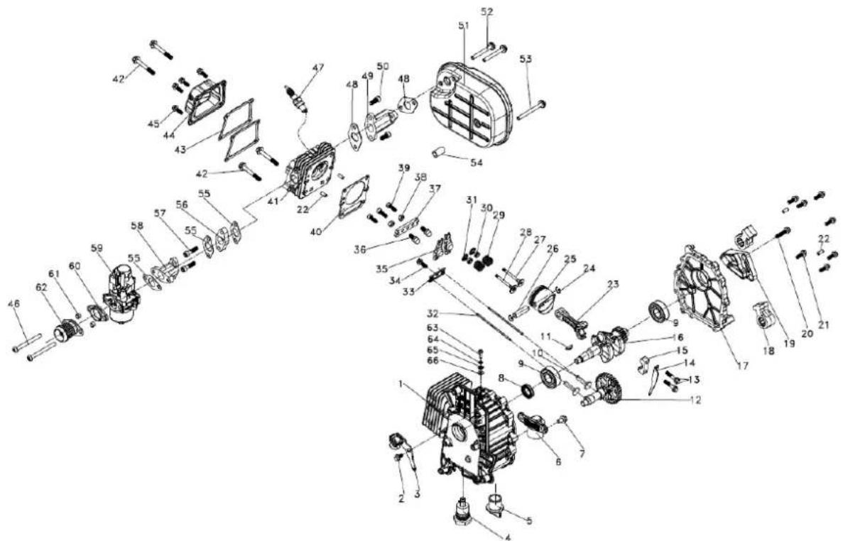
| # | Description | Qty | # | Description | Qty |
| 1 | crankshaft box | 1 | 34 | Hexagon head bolt (thread root with R) M5x8 | 1 |
| 2 | Hexagon flange bolts M5x12 | 1 | 35 | valve rocker | 2 |
| 3 | Trigger | 1 | 36 | adjusting screw M6 | 2 |
| 4 | Oil sensor | 1 | 37 | Rocker arm fixing plate | 1 |
| 5 | oil filter cap | 1 | 38 | Thin tooth type 1 hexagon nut M6x0,75 | 2 |
| 6 | Oil sensor guard | 1 | 39 | hexagon socket cap screws M5x16-3p(3) | 3 |
| 7 | Hexagon flange bolts M6x12 | 1 | 40 | Cylinder compound pad | 1 |
| 8 | crankshaft oil seal | 1 | 41 | cylinder head | 1 |
| 9 | deep groove ball bearing | 2 | 42 | Hexagon flange bolts M6x45 | 4 |
| 10 | valve lifter | 2 | 43 | Cylinder head seal | 2 |
| 11 | woodruff key | 1 | 44 | Cylinder hood assembly | 1 |
| 12 | CAM relief assembly | 1 | 45 | Hexagon flange bolts M5x16 | 4 |
| 13 | Hexagon flange bolts | 2 | 46 | cross recess pan head screw M6x65 | 2 |
| 14 | oil dipper | 1 | 47 | spark plug | 1 |
| 15 | connecting rod cap | 1 | 48 | muffler gasket | 2 |
| 16 | crankshaft assembly | 1 | 49 | muffler connecting pipe | 1 |
| 17 | Housing plate | 1 | 50 | hexagon socket cap screws M6x16 | 2 |
| 18 | Rubber hook | 2 | 51 | muffler assembly | 1 |
| 19 | Support foot fixing frame | 1 | 52 | Hexagon flange bolts M6x50 | 2 |
| 20 | Hexagon flange bolts M5x35 | 1 | 53 | Hexagon flange bolts M6x85 | 1 |
| 21 | Hexagon flange bolts M5x16 | 7 | 54 | muffler supporting tube | 1 |
| 22 | Box locating pin | 4 | 55 | Carburator gasket (out) | 3 |
| 23 | connecting rod | 1 | 56 | Thermal insulation gasket | 1 |
| 24 | piston pin clamping spring | 2 | 57 | hexagon socket cap screws M6x25 | 2 |
| 25 | piston assembly | 1 | 58 | Carburetor connection | 1 |
| 26 | piston pin | 1 | 59 | Carburetor assembly | 1 |
| 27 | valve exhaust | 1 | 60 | inlet flange | 1 |
| 28 | intake valve | 1 | 61 | Mat tube Φ8x1.0 | 2 |
| 29 | valve spring | 2 | 62 | Air filter connection pipe | 1 |
| 30 | Valve seal ring | 2 | 63 | cross recess pan head screw M5x16 | 1 |
| 31 | Valve spring snap | 2 | 64 | spring washer ø5 | 1 |
| 32 | valve push rod | 2 | 65 | Serrated lock washers internal teeth ø5 | 1 |
| 33 | Push rod guide plate | 1 | 66 | flat washer ø5 | 1 |
Company ZIPPER Maschinen GmbH grants for mechanical and electrical components a warranty period of 2 years for amateur use; and warranty period of 1 year for professional use, starting with the purchase of the final consumer. In case of defects during this period, which are not excluded by paragraph 3, ZIPPER will repair or replace the machine at its own discretion.
2.) Report:
In order to check the legitimacy of warranty claims, the final consumer must contact his dealer. The dealer has to report in written form the occurred defect to ZIPPER. If the warranty claim is legitimate, ZIPPER will pick up the defective machine from the dealer. Returned shippings by dealers which have not been coordinated with ZIPPER, will not be accepted and refused.
3.) Regulations:
a) Warranty claims will only be accepted, when a copy of the original invoice or cash voucher from the trading partner of ZIPPER is enclosed to the machine. The warranty claim expires if the accessories belonging to the machine are missing.
b) The warranty does not include free checking, maintenance, inspection or service works on the machine. Defects due to incorrect usage of the final consumer or his dealer will not be accepted as warranty claims either. Some examples: usage of wrong fuel, frost damages in water tanks, leaving fuel in the tank during the winter, etc.
c) Defects on wear parts are excluded, e.g. carbon brushes, collection bags, knives, cylinders, cutting blades, clutches, sealings, wheels, saw blades, splitting crosses, riving knives, riving knife extensions, hydraulic oils, oil/air/fuel filters, chains, spark plugs, sliding blocks, etc.
d) Also excluded are damages on the machine caused by incorrect or inappropriate usage, if it was used for a purpose which the machine is not supposed to, ignoring the user manual, force majeure, repairs or technical manipulations by not authorized workshops or by the customer himself, usage of non-original ZIPPER spare parts or accessories.
e) After inspection by our qualified personnel, resulted costs (like freight charges) and expenses for not legitimated warranty claims will be charged to the final customer or dealer.
f) In case of defective machines outside the warranty period, we will only repair after advance payment or dealer's invoice according to the cost estimate (incl. freight costs) of ZIPPER.
g) Warranty claims can only be granted for customers of an authorized ZIPPER dealer who directly purchased the machine from ZIPPER. These claims are not transferable in case of multiple sales of the machine.
4.) Claims for compensation and other liabilities:
The liability of company ZIPPER is limited to the value of goods in all cases. Claims for compensation because of poor performance, lacks, damages or loss of earnings due to defects during the warranty period will not be accepted. ZIPPER insists on its right to subsequent improvement of the machine.
44 GARANTIE (FR)
1.) Garantie:
Product experience form
We observe the quality of our delivered products in the frame of a Quality Management policy.
Your opinion is essential for further product development and product choice. Please let us know about your:
- Impressions and suggestions for improvement.
- experiences that may be useful for other users and for product design
- Experiences with malfunctions that occur in specific operation modes
We would like to ask you to note down your experiences and observations and send them to us via FAX, E-Mail or by post:
Erworben von / purchased from:
E-Mail/ e-mail:
Please describe amongst others in the problem: What has cause the problem/defect, what was the last activity before you noticed the problem/defect? For electrical problems: Have you had checked you electric supply and the machine already by a certified electrician?
3. Bitte beachten
/ Additional information
INCOMPLETELY FILLED SERVICE FORMS CANNOT BE PROCESSED! FOR GUARANTEE CLAIMS PLEASE ADD A COPY OF YOUR ORIGINAL SALES / DELIVERY RECEIPT OTHERWISE IT CANNOT BE ACCEPTED. FOR SPARE PART ORDERS PLEASE ADD TO THIS SERVICE FORM A COPY OF THE RESPECTIVE EXPLODED DRAWING WITH THE REQUIRED SPARE PARTS BEING MARKED CLEARLY AND UNMISTAKABLE. THIS HELPS US TO IDENTIFY THE REQUIRED SPARE PARTS FASTLY AND ACCEL- LERATES THE HANDLING OF YOUR INQUIRY.


- 1 INHALT / INDEX
- 1 INHALT / INDEX 2
- 11 OPERATION 24
- 12 MAINTENANCE 26
- 13 TROUBLE SHOOTING 29
- 14 PRÉFACE (FR) 30
- 15 SÉCURITÉ 31
- 3.2 TECHNISCHE DATEN / TECHNICAL DATA / DONNÉES TECHNIQUES / TEHNIČKI PODACI / TEHNIČNI PODATKI / MŮSZAKI ADATOK / TECHNICKÉ ÚDAJE
- 4 VORWORT (DE)
- 6.3.2 STOPPEN
- 7.7 TRANSPORT
- 7.9 ENTSORGUNG
- PLEASE READ AND OBEY THE SECURITY INSTRUCTIONS
- COPYRIGHT
- CUSTOMER SUPPORT
- 10.1 INTENDED USE OF THE MACHINE
- ZIPPER-MASCHINEN ASSUMES NO RESPONSIBILITY OR WARRANTY FOR ANY OTHER USE OR USE BEYOND THIS AND FOR ANY RESULTING DAMAGE TO PROPERTY OR INJURY
- 10.1.1 TECHNICAL RESTRICTIONS
- 10.1.2 PROHIBITED USE / FORSEEABLE MISUSE
- 10.2 USER REQUIREMENTS
- PLEASE NOTE THAT LOCAL LAWS AND REGULATIONS MAY DETERMINE THE MINIMUM AGE OF THE OPERATOR AND RESTRICT THE USE OF THIS MACHINE
- 10.3 SAFETY INSTRUCTIONS
- 10.4 SPECIAL SAFETY INSTRUCTIONS FOR THE OPERATION OF THE MACHINE
- 10.5 SAFETY INSTRUCTIONS FOR MACHINES WITH COMBUSTION ENGINE
- 10.6 HAZARD WARNINGS
- RISK OF BURNS
- RISK OF FIRE AND EXPLOSION
- CHEMICAL RISKS
- RISK OF ELECTRIC SHOCK
- HEARING DAMAGE
- DANGER
- WARNING
- CAUTION
- NOTICE
- 11 OPERATION
- 11.1 PRE-OPERATION CHECK
- 11.1.1 CHECK ENGINE OIL
- 11.1.2 CHECK FUEL
- 11.2 OPERATION INSTRUCTIONS
- NOT ICE
- 11.3 OPERATION
- 11.3.1 START
- 11.3.2 STOP
- AT LONGER BREAKS
- 12 MAINTENANCE
- 12.1 MAINTENANCE PLAN
- 12.2 CLEANING
- 12.3 ENGINE OIL CHANGE
- 12.4 AIR CLEANER
- 12.5 SPARK PLUG
- 12.6 FUEL TANK AND FUEL FILTER
- 12.7 TRANSPORT
- 12.8 STORAGE
- 12.9 DISPOSAL
- 14 PRÉFACE (FR)
- CHER CLIENT
- 17 ENTRETIEN
- ATTENTI ON
- 17.7 TRANSPORT
- 17.9 RECYCLAGE
- NE ULIJEVAJTE GORIVO KADA
- 21.2 UPUTE ZA RAD
- NAP OMENA
- 22.5 SVJEĆICA
- 22.6 SPREMNIK GORIVA I FILTAR GORIVA
- 22.7 TRANSPORT
- 22.9 ODLAGANJE
- 26.3.2 ZAUSTAVITEV
- 27 VZDRŽEVANJE
- OPOZORILO
- 27.4 ZRAČNI FILTER
- 27.5 SVEČKA
- 27.6 REZERVOAR BENCINA IN FILTER ZA BENCIN
- 27.7 TRANSPORT
- 27.9 ODSTRANJEVANJE
- 31.3.2 LEÁLLÍTÁS
- FIGYELEM
- 32.4 LEVEGŐSZŰRŐ
- 32.5 GYÚJTÓGYERTYA
- 32.7 SZÁLLÍTÁS
- 36.2 PROVOZNÍ POKYNY
- POKYN
- 37 ÚDRŽBA
- VAROVÁNÍ
- 37.7 TRANSPORT
- 37.9 LIKVIDACE
- IMPORTANT
- THE INSTALLATION OF OTHER THAN ORIGINAL SPARE PARTS VOIDS THE WARRANTY
- 2.) REPORT
- 3.) REGULATIONS
- 4.) CLAIMS FOR COMPENSATION AND OTHER LIABILITIES
- 44 GARANTIE (FR)
- 1.) GARANTIE
- PRODUCT EXPERIENCE FORM
- BITTE BEACHTEN
- ADDITIONAL INFORMATION
Brand : Zipper
Model : ZISTE1100IV
Category : Generator