
PWS110CM1 - Server SONY - Free user manual and instructions
Find the device manual for free PWS110CM1 SONY in PDF.
| Product Type | Video content management server for 4K-Live systems |
| Brand | Sony |
| Model | PWS110CM1 |
| Dimensions (W × H × D) | 440 × 43.6 × 507 mm |
| Weight | 9.7 kg |
| Power supply | 100-240 V AC, 50/60 Hz; power consumption 235 W (standby ≤3 W) |
| Processor | Intel Core i7 6700TE (2.4 GHz) |
| RAM memory | 8 GB |
| Internal storage | M.2 SSD 120 GB + PCIe SSD 1.2 TB or 2.0 TB (Intel DC P3600/P4600) |
| Network connectivity | 2 × Gigabit LAN, 1 × PCIe slot for 10GbE card (Intel X520-DA1) |
| Front connectors | 2 × USB 3.0 (900 mA/port), power/standby button, SYSTEM and LED indicators |
| Rear connectors | 4 × USB 3.0 (1 with 900 mA power), 1 × HDMI, 1 × DisplayPort, 2 × LAN, 2 × AC power |
| Main functions | Video content management on PWS-4500/BPU4800, workflow creation, metadata editing via web browser, sorting and transfer to NAS |
| User interface | Web application (maintenance) accessible via Chrome browser on client PC |
| Operating system | Windows 8.1/10 64-bit (integrated) |
| Operating temperature | 5 °C to 35 °C |
| Operating humidity | 20% to 90% (non-condensing) |
| Safety | Use of a UPS recommended; mandatory grounding; precautions against data loss |
| Maintenance | Check FAN, POWER and TEMP indicators on the removed front panel |
| Spare parts / Repairability | Optional power supply PWSK-101 (redundancy); Intel X520-DA1 network card; contact Sony support for installation/replacement |
| User manual | 70 pages, available in multiple languages (FR, EN, DE, ES, IT, JA, KO, ZH) |
Frequently Asked Questions - PWS110CM1 SONY
User questions about PWS110CM1 SONY
0 question about this device. Answer the ones you know or ask your own.
Ask a new question about this device
Download the instructions for your Server in PDF format for free! Find your manual PWS110CM1 - SONY and take your electronic device back in hand. On this page are published all the documents necessary for the use of your device. PWS110CM1 by SONY.
USER MANUAL PWS110CM1 SONY
Japanese/English/French/German/Italian/Spanish/Chinese/Korean
目次
概要 3
3
对应機器 3
对应 NIC 3
各部の名称と功. 4
前面 4
前面(八不尔を外した场合)
背面 5
準備 6
初期設定 6
APRIKEN6
7
7
XmntannsAprkeonnの操作 7
使用上の注意 8
仕樣 8
Series-1_2TB-12-Height-PCIe-3_0-20nm-MLC
Intel Solid-State Drive DC P4600
https://ark.intel.com/products/96999/Intel-SSD-DC-P4600
Series-2_0TB-12-Height-PCIe-3_1-x4-3D1-TLC
拲張八PCIeGen28Lane(30W)(2)
入出力
LAN RJ-45 (2)
1000BASE-T
100BASE-TX
SFP + (1)
10GBASE-SR/LR (Add-in Card) 1)2
1)本機以接續載之在的不和力一卡一
Intel Ethernet Converged Network Adapter X520-DA1
System Configuration and Connection 11
Supported Devices 11
Supported NIC 11
Name and Function of Parts. 12
Front View 12
Front View (Panel Removed) 12
Rear View. 13
Setting Up. 14
Initial Settings 14
Displaying the Application 14
Application Settings. 15
System Settings 15
Maintenance Web Application Operation. 15
Usage Precautions 16
Specifications 16
For safety, please read the precautions described in the PWS-110 Operation Guide (supplied).
Overview
This unit is a system that manages video content stored on a PWS-4500/BPU4800 in a 4K-Live system.
Users can build workflows using the metadata of video content, edit the metadata from a web browser, sort video content on multiple PWS-4500/BPU4800 units, and transfer video content efficiently between PWS-4500/ BPU4800 units and to NAS or other external storage.
For details about operation, refer to the Help in the application.
System Configuration and Connection
Connect the unit to a 4K-Live system using Ethernet.
Notice to customers
Installation of the unit should be performed by your Sony service personnel or a technician who has received service training.
Supported Devices
Operation with the following devices has been certified.
Supported NIC
Operation with the following 10 GbE network card has been certified.
Intel Ethernet Converged Network Adapter X520-DA1
Name and Function of Parts
Front View
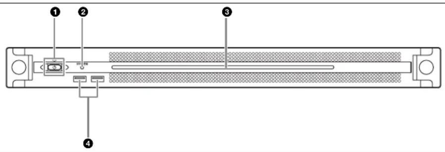
On/Standby button and indicator
Switches the unit on/off (standby state). Connecting the power cord places the unit in standby state, and the indicator turns on red. Pressing the On/Standby button while in standby state turns on the unit and the indicator turns on green. Pressing and holding the On/Standby button for two seconds switches the unit to standby state, and the indicator changes to red. To turn the unit on again after switching from On state to standby state, when the indicator is red, press and hold the On/Standby button for three seconds or longer. The indicator goes out when the power cord is disconnected.
SYSTEM indicator
Indicates the status of the unit.
Green: Operating normally
Flashing green (once per second): System is booting or transitioning to standby state.
Flashing orange (once per second): A warning has been generated.
High-speed flashing read (four times per second): An error has occurred.
③Front panel LED
Turns on according to settings in the web application. The LED is configured using [001: LINE LED] in the [Settings] page on the Maintenance screen.
4USB connectors (front panel)
Connects to a keyboard and mouse for initializing the unit. USB devices not described in this document are not supported.
Notes
- Both USB ports on the front panel support power delivery (900 mA).
- Use SuperSpeed USB cables.
Front View (Panel Removed)
When the SYSTEM indicator or web application indicates an error, you can remove the front panel to check the status of the hardware components.
To remove the front panel, loosen the screws on the left and right sides and pull the panel towards you.
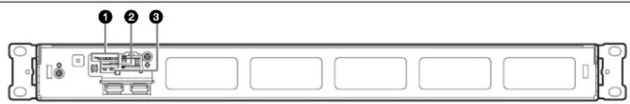
FAN indicators
If any of the fans fail, the corresponding fan indicator turns on red.
POWER indicators
If either of the AC power supply units fail, the corresponding indicator turns on red.
3TEMP indicator
If an abnormally high temperature is detected within the unit, the indicator turns on red.
Rear View
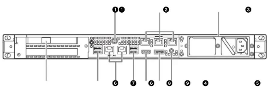
SYSTEM TC connector
Not used by this system.
Remote connectors (1/2, 3/4, 5)
Not used by this system.
AC power supply units
Insert the power cords and connect to power outlets. Only one AC power supply unit is installed at the factory. A second optional power supply unit can be installed to provide power supply redundancy. When used in systems that require reliability, power supply redundancy allows the unit to continue operating even if a power supply unit fails.
For details about installing or replacing a power supply unit, consult your Sony sales or service representative.
4SFP+ slot
Attach to an SFP + module.
USB connectors (rear panel)
Connect to drive units using USB cables.
USB devices not described in this document are not supported.
Notes
- Of the four USB connectors on the rear panel, only the bottom right port supports power delivery (900 mA). The other three ports do not support power delivery, and should be used to connect USB devices that do not require power supplied from the USB connector.
- Use SuperSpeed USB cables.
6LAN connectors
Connect to a Gigabit Ethernet network.
7HDMI connector
Connect to a monitor using an HDMI cable.
Use an HDMI cable that conforms to the following standard.
- High Speed HDMI Cable (Premium High Speed HDMI Cable)
③DisplayPort connector
Connect to a monitor using a DisplayPort-to-DVI converter cable or DisplayPort-to-HDMI converter cable. Use an active-type converter cable.
Note
Use a DisplayPort cable that conforms to the following standard.
- DP v1.2a (compliant)
Ground terminal
Connect to ground.
Setting Up
Initial Settings
Before using the unit, configure the Windows settings within the unit. The description below describes the standard settings in Windows 8.
Note
To reboot the unit, first shut down the unit and then turn the On/Standby button on the front panel on again, without rebooting Windows.
1 Connect a keyboard and mouse to the USB connectors on the front panel, and connect a monitor to the DisplayPort connector or HDMI connector on the rear panel.
2 Turn the On/Standby button on.
3 When the Windows login screen appears, enter "cm1" as the user name and "cm1" as the password, and log in.
Configuring the network
1 Connect a LAN cable to the LAN connector on the rear panel of the unit, and connect the other end to the network.
2 Click [View network status and tasks] under [Network and Internet] in the control panel.
3 Click the device connected by LAN cable in [Connections].
4 Click the [Properties] button.
5 Select [Internet Protocol Version 4 (TCP/IPv4)], then click the [Properties] button.
6 Change the IP address and other settings.
7 Click the [Advanced] button to configure DNS, WINS, and other settings.
8 When finished, click the [OK] button.
Setting the date and time
1 Select [Set the time and date] under [Date and Time] in the [Clock, Language, and Region] control panel.
2 Click [Change time zone] on the [Date and Time] tab, and select the time zone.
3 Click [Change date and time] on the [Date and Time] tab, and set the date and time.
4 Click the [Change settings] button on the [Internet Time] tab.
5 Specify an NTP server, then click the [Update Now] button.
6 Place a check mark in [Synchronize with an Internet time server] to periodically correct the clock using the NTP server.
Signing out
When finished, sign out from Windows.
1 Move the mouse cursor to the top right corner of the screen to display the Charms bar, then click [Start].
2 Click the account name on the top right of the screen, then click [Sign out].
Displaying the Application
Connect a client PC to the unit via the network to display the application in a web browser on the client PC in order to configure and control the unit.
Recommended client PC environment
CPU: Intel Core i7 or higher
Memory: 4 GB or higher
Storage: 1 TB or higher
Network: Gigabit LAN port (1)
Graphics: nVidia Quadro FX series, NVS series or higher
OS: Windows 8.1 (64-bit version)
Windows 10 (64-bit version)
Web browser: Google Chrome
Display resolution:
1920 × 1080 pixels or higher
Connect a computer satisfying the recommended conditions above to the LAN1 or LAN2 connector on the rear panel of the unit. Enter "https://(host_name)/cm1/" in the address bar of a web browser on the computer to display the application.
Enter the user name and password when the login screen appears.
The following user name and password are configured by default.
User name: admin
Password: cm1
Application Settings
Launch the application and configure the required system settings.
For details about configuration, refer to the Help in the application.
System Settings
Configure the system settings on the Maintenance screen in the web application.
For details about the Maintenance screen, see
"Maintenance Web Application Operation" on page 15.
Maintenance Web Application Operation
For details about the operation of the Maintenance Web Application for system administrators, log in to the unit and click the shortcut icon on the desktop to refer to the Operation Manual.
Usage Precautions
Power supply precautions
If the unit is suddenly turned off during operation, data loss may occur. To maintain data integrity, the use of an uninterrupted power supply (UPS) is recommended. To disconnect the power cord or turn off the breaker, always press the On/Standby button on the unit to stop the unit before proceeding.
USB device precautions
When using the unit when connected to a self-powered USB device (such as the ODS-D77U), the device may not be recognized, depending on the timing of when the device is turned on. If this occurs, turn the USB device off and on again, or disconnect and reconnect the USB cable.
Specifications
General
Power requirement 100 V to 240 V AC 50/60 Hz
Power consumption 235 W
Standby power consumption 3 Wor lower
Operating temperature 5^ to 35^ (41 F to 95 F)
Storage temperature -20^ to +60^ (-4^ to +140^)
Operating humidity 20% to 90% (relative humidity)
Storage humidity 5% to 80%
Mass 9.7kg (21 lb. 6.2 oz.)
Dimensions 440× 43.6× 507mm (17^3 / 8× 1^3 / 4× 20 in.) (width / height / depth)

CPU
Processor Intel Core i7 6700TE (2.4 GHz)
Memory 8 GBytes SO-DIMM (DDR4) (2)
Drive (M.2) 120 GBytes
Drives (SSD) PCIe SSD (Add-in Card), 1.2 TBytes or 2.0 TBytes
One of the following PCIe SSDs is connected to the unit.
Intel Solid-State Drive DC P3600 (1.2 TBytes)
Intel Solid-State Drive DC P4600 (2.0 TBytes)
For details about PCIe SSDs, visit the following sites.
Intel Solid-State Drive DC P3600
https://ark.intel.com/products/80990/Intel-SSD-DC-P3600-Series1_2TB-12-Height-PCIe-3_0-20nm-MLC
Intel Solid-State Drive DC P4600
https://ark.intel.com/products/96999/Intel-SSD-DC-P4600_Scrics2_0TB-12-Height-PCie-3_1-x4-3D1-TLC
Expansion bus PCIe Gen2 8Lane (30 W) (2)
Inputs/outputs
LAN RJ-45 (2)
1000BASE-T
100BASE-TX
SFP + (1)
10GBASE-SR/LR (Add-in Card) ^1)2)
1) Network card connected to the unit Intel Ethernet Converged Network Adapter X520-DA1 For information about the network card, visit the following site. http://www.intel.com/support/go/network/adapter/userguide.htm
2) Supported only when SFP+ module is attached.
USB(front panel/rear panel)
Super Speed USB (USB 3.0) Type A (6,2 on front and 4 on rear)
Front: Power delivery support (900 mA/ port)
Rear: Power delivery support on bottom right port (900mA) not supported on other three ports
HDMI Type A (1)
HDMI Ver. 1.4a, 1920× 1200 maximum resolution, 60Hz
DisplayPort DisplayPort (1)
DisplayPort Ver. 1.1a, 2560 × 1600 maximum resolution, 60Hz
Optional accessories
PWSK-101 Optional Power Supply
Design and specifications are subject to change without notice.
Depending on the operating environment, unauthorized third parties on the network may be able to access the unit. When connecting the unit to the network, be sure to confirm that the network is protected securely.
Notes
- Always make a test recording, and verify that it was recorded successfully.
- SONY WILL NOT BE LIABLE FOR DAMAGES OF ANY KIND INCLUDING, BUT NOT LIMITED TO, COMPENSATION OR REIMBURSEMENT ON ACCOUNT OF FAILURE OF THIS UNIT OR ITS RECORDING MEDIA, EXTERNAL STORAGE SYSTEMS OR ANY OTHER MEDIA OR STORAGE SYSTEMS TO RECORD CONTENT OF ANY TYPE.
- Always verify that the unit is operating properly before use. SONY WILL NOT BE LIABLE FOR DAMAGES OF ANY KIND INCLUDING, BUT NOT LIMITED TO, COMPENSATION OR REIMBURSEMENT ON ACCOUNT OF THE LOSS OF PRESENT OR PROSPECTIVE PROFITS DUE TO FAILURE OF THIS UNIT, Either DURING THE WARRANTY PERIOD OR AFTER EXPIRATION OF THE WARRANTY, OR FOR ANY OTHER REASON WHATSOEVER.
- SONY WILL NOT BE LIABLE FOR CLAIMS OF ANY KIND MADE BY USERS OF THIS UNIT OR MADE BY THIRD PARTIES.
- SONY WILL NOT BE LIABLE FOR THE LOSS, REPAIR, OR REPRODUCTION OF ANY DATA RECORDED ON THE INTERNAL STORAGE SYSTEM, RECORDING MEDIA, EXTERNAL STORAGE SYSTEMS OR ANY OTHER MEDIA OR STORAGE SYSTEMS.
-
SONY WILL NOT BE LIABLE FOR THE TERMINATION OR DISCONTINUATION OF ANY SERVICES RELATED TO THIS UNIT THAT MAY RESULT DUE TO CIRCUMSTANCES OF ANY KIND.
-
Windows is a registered trademark of Microsoft Corporation in the United States and other countries.
- Google Chrome is a trademark or registered trademark of Google Inc.
Other products or system names appearing in this document are trademarks or registered trademarks of their respective owners. Further, the or TM symbols are not used in the text.
This Product uses the Source Code of T-Kernel 2.0 under T-License 2.1 granted by TRON Forum (www.tron.org).
For the customers in Taiwan
$$ \text {S O - D I M M} (\text {D D R 4}) (2) $$
PCIc Gen2 8Lane (30 W) (2)
Entrées/Sorties
LAN RJ-45 (2)
1000BASE-T
100BASE-TX
SFP + (1)
10GBASE-SR/LR (Carte d'extension) 1) 2)
1920 × 1200 resolution maximale,
60Hz
DisplayPort DisplayPort (1)
DisplayPort Ver. 1.1a,
PCIc Gen2 8Lane (30 W) (2)
Eingänge/Ausgänge
LAN RJ-45 (2)
1000BASE-T
100BASE-TX
SFP + (1)
PCIe Gen2 8Lane (30 W) (2)
Ingressi/uscite
LAN RJ-45 (2)
1000BASE-T
100BASE-TX
SFP + (1)
https://ark.intel.com/products/96999/Intel-SSD-DC-P4600-Series
2_0TB-12-Height-PCIe-3_1-x4-3D1-TLC
Extension del bus
PCIc Gen2 8Lane (30 W) (2)
Entradas/salidas
LAN RJ-45 (2)
1000BASE-T
100BASE-TX
SFP + (1)
10GBASE-SR/LR (tarjeta complementaria) 1)2
1920 × 1200 resolution maxima,
60 Hz
DisplayPort DisplayPort (1)
DisplayPort Ver. 1.1a,
2560 × 1600 resolution maxima,
60 Hz
gikaiB3iEeBnB3WbKoEey
HDMI
10GBASE-SR/LR (Add-in Card)
1)增切,
Intel Ethernet Converged Network Adapter X520-DA1
国三用克卡三部上国海
http://www.intel.com/support/go/network/adapter/userguide.htm
2)SFP+我可I首中自
USB(半双脚/三脚)
Super Speed USB(USB 3.0)
taioA(6,2,4)
音:
(900mA/王旦)
経剸:○長剸あ連亘是開元國
哉原(900mA),,
志川人
HDMI TAIJIA A(1)
HDMI 胜原.1.4a,
The material contained in this manual consists of information that is the property of Sony Corporation and is intended solely for use by the purchasers of the equipment described in this manual.
Sony Corporation expressly prohibits the duplication of any portion of this manual or the use thereof for any purpose other than the operation or maintenance of the equipment described in this manual without the express written permission of Sony Corporation.


- 目次
- 入出力
- Overview
- System Configuration and Connection
- Notice to customers
- Supported Devices
- Supported NIC
- Name and Function of Parts
- Front View
- On/Standby button and indicator
- SYSTEM indicator
- ③Front panel LED
- 4USB connectors (front panel)
- Notes
- Front View (Panel Removed)
- FAN indicators
- POWER indicators
- 3TEMP indicator
- Rear View
- SYSTEM TC connector
- Remote connectors (1/2, 3/4, 5)
- AC power supply units
- 4SFP+ slot
- USB connectors (rear panel)
- 6LAN connectors
- 7HDMI connector
- ③DisplayPort connector
- Note
- Ground terminal
- Setting Up
- Initial Settings
- Configuring the network
- Setting the date and time
- Signing out
- Displaying the Application
- Recommended client PC environment
- Application Settings
- System Settings
- Maintenance Web Application Operation
- Usage Precautions
- Power supply precautions
- USB device precautions
- Specifications
- General
- CPU
- Inputs/outputs
- Optional accessories
- Entrées/Sorties
- Eingänge/Ausgänge
- Ingressi/uscite
- Entradas/salidas
- HDMI
Brand : SONY
Model : PWS110CM1
Category : Server