
HeavyCoat 970 E SSP - Paint spray WAGNER - Free user manual and instructions
Find the device manual for free HeavyCoat 970 E SSP WAGNER in PDF.
| Product type | Airless paint sprayer |
| Brand | Wagner |
| Model | HeavyCoat 970 E SSP |
| Maximum working pressure | 25 MPa (250 bar) |
| Maximum flow rate | 10 l/min |
| Power supply | 400 V, 50 Hz, three-phase, 5.5 kW |
| Weight | 103 kg |
| Dimensions (L x W x H) | 1200 x 955 x 655 mm |
| Hydraulic oil capacity | 4.7 L (ISO 32) |
| High pressure hose | DN 13 mm, 15 m, NPSM 1/2" connection |
| Whip hose | DN 10 mm, 2.5 m, NPSM 3/8" connection |
| Maximum product temperature | 43°C |
| Maximum viscosity | 65,000 mPa·s |
| Maximum nozzle orifice | 0.056 inch (1.42 mm) |
| Sound level | 88 dB(A) |
| Safety protection | Mandatory grounding, trigger lock, nozzle protection |
| Maintenance | Oil change every 12 months, high pressure filter cleaning |
| Spare parts | Available (see list in manual) |
| Warranty | 3+2 years (Professional Finishing) |
Frequently Asked Questions - HeavyCoat 970 E SSP WAGNER
User questions about HeavyCoat 970 E SSP WAGNER
0 question about this device. Answer the ones you know or ask your own.
Ask a new question about this device
Download the instructions for your Paint spray in PDF format for free! Find your manual HeavyCoat 970 E SSP - WAGNER and take your electronic device back in hand. On this page are published all the documents necessary for the use of your device. HeavyCoat 970 E SSP by WAGNER.
USER MANUAL HeavyCoat 970 E SSP WAGNER
natural_image
Technical line drawing of a HC 950 230V pressure pump with hoses and control panel (no text or symbols on the device itself)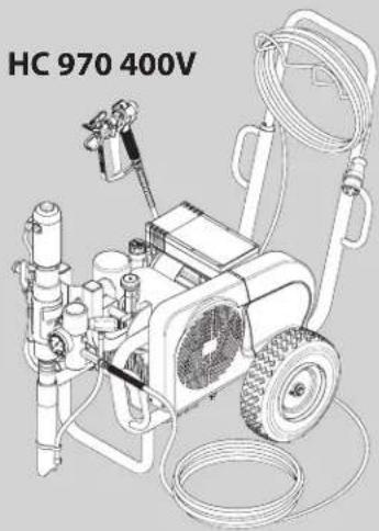
natural_image
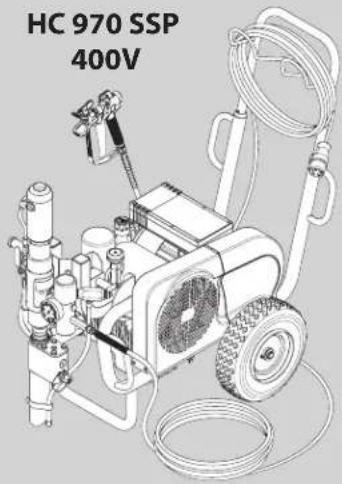
Technical line drawing of a mechanical pressure pump unit (HC 970 400V) with hoses and control panel (no text or symbols on the device itself)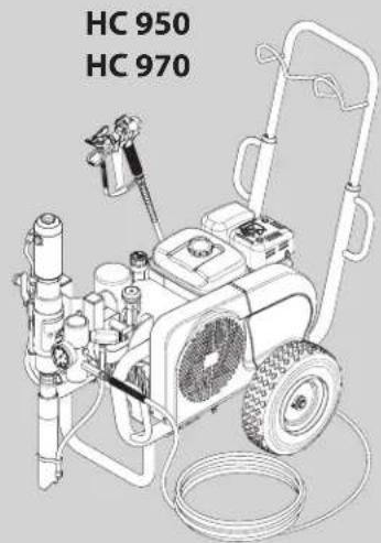
natural_image
Line drawing of a water purifier with labeled components (HC 950, HC 970), no text or symbols on the device itself.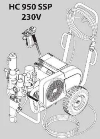
natural_image
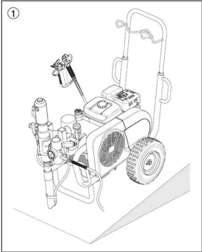
Technical line drawing of a HC 970 SSP 400V pressure pump with hoses and control panel (no text or symbols on the equipment itself)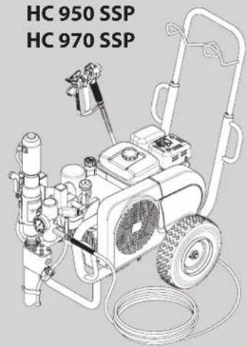
HEAVYCOAT (HC)
950 · 970
BETRIEBSANLEITUNG • OWNER'S MANUAL MODE D'EMPLOI • INSTRUZIONI PER L'USO

Warnung!

natural_image
Line drawing of a portable electric water heater with attached hoses and control panel (no text or symbols)④
3.11 Krantransport
natural_image
Line drawing of a mechanical pump or cart with attached motors and suspension cables (no text or symbols)4. Inbetriebnahme
1. Transportposition (Abb. 9)
natural_image
Line drawing of a portable lawn mower with visible blades and wheels (no text or symbols)natural_image
Line drawing of a mechanical power supply unit with hoses and valves (no text or symbols)natural_image
Line drawing of a portable electric water heater with attached pump and wheels (no text or symbols)natural_image
Technical line drawing of a mechanical assembly with a magnified inset showing a hand operating a valve (no text or symbols present)natural_image
Illustration of a mechanical device with no visible text or symbolsT el. 0 50 32-8 00 06 23
Telefax 0 50 32-8 00 06 24
München
Jahnke GmbH
Hochstraße 7
82024 Taufkirchen
Tel. 0 89 /6 14 00 22
Telefax 0 89 / 6 14 04 33
email: info@airless.de
www.airless.de
Nürnberg
Grimmer GmbH
Starenweg 28
91126 Schwabach
Tel. 0 91 22 / 7 94 73
Telefax 0 91 22 / 7 94 75 0
email: info@grimmer-sc.de
www.grimmer-sc.de
Markdorf – Zentrale
J. WAGNER GmbH
Attention: Danger of injury by injection! Airless units develop extremely high spraying pressures.


Never put your fingers, hands or any other parts of the body into the spray jet!
Never point the spray gun at yourself, other persons or animals.
Never use the spray gun without safety guard.
Do not treat a spraying injury as a harmless cut. In case of injury to the skin through coating materials or solvents, consult a doctor immediately for quick and expert treatment. Inform the doctor about the coating material or solvent used.

The operating instructions state that the following points must always be observed before starting up:
- Faulty units must not be used.
- Secure WAGNER spray gun using the safety catch on the trigger.
- Ensure that the unit is properly earthed.
- Check allowable operating pressure of high-pressure hose and spray gun.
- Check all connections for leaks.

The instructions regarding regular cleaning and maintenance of the unit must be strictly observed.
Before any work is done on the unit or for every break in work the following rules must be observed:
- Release the pressure from spray gun and hose.
- Secure the WAGNER spray gun using the safety catch on the trigger.
- Switch off unit.
Be safety conscious!
Contents
Page
- Safety regulations for Airless spraying 26
1.1 Explanation of symbols used 26
1.2 Electrical safety....27
1.3 Gasoline engine safety 28
1.4 Setting up on uneven surfaces 28
- General view of application....29
2.1 Application 29
2.2 Coating materials....29
- Description of unit....29
3.1 Airless process....29
3.2 Functioning of the unit 29
3.3 Illustration legend for gasoline HC units 30
3.4 Illustration of gasoline HC units 30
3.5 Illustration legend for electric HC units 31
3.6 Illustration of electric HC units 31
3.7 Technical data for gasoline HC units 32
3.8 Technical data for electric HC units 33
3.9 Transport 34
3.10 Transport in vehicle 34
3.11 Crane transport 34
- Starting operation....35
4.1 Changing the material feed pump position 35
4.2 High-pressure hose, spray gun and separating oil ....36
4.3 Gasoline engine (gas units only) 36
4.4 Connection to the mains (electric units only) 36
4.5 Flushing preserving fluid during initial start-up 36
4.6 Taking the unit into operation with coating material....37
- Spraying technique 37
- Handling the high-pressure hose ....37
-
Interruption of work....37
-
Cleaning the unit (shutting down) 38
8.1 Cleaning the unit from the outside 38
8.2 Cleaning the high-pressure filter 38
8.3 Cleaning Airless spray gun 39
Page
- Remedy in case of faults....40
9.1 Gasoline engine 40
9.2 Electric motor 40
9.3 Hydraulic motor 40
9.4 Material feed pump 41
- Servicing....42
10.1 General servicing 42
10.2 Checking the oil level in the hydraulic oil tank 42
10.3 Oil and oil filter change of the hydraulic oil pump ....42
10.4 High-pressure hose....42
- Appendix......43
11.1 Selection of tip 43
11.2 Servicing and cleaning of Airless hard-metal tips ....43
11.3 Spray gun accessories 43
11.4 Airless tip table 44/45
11.5 2Speed Tip table ....46
Sales and service companies....47
Accessories and spare parts 96
Accessories for HC units I 96/97
Accessories for HC units II 98/99
Spare parts list for the main assembly 100/101
Spare parts list for the cart assembly 102/103
Spare parts list for the hydraulic system 104/105
Spare parts list for the hydraulic motor 106/107
Spare parts list for the fluid section 108/109
Spare parts list for the shovel valve
HC 950-SSP • HC 970-SSP....110/111
Spare parts list for the high-pressure filter 112/113
Spare parts list for electric convertokit (230V / 400V) ....114
Spare parts list for gas convertokit 116
Spare parts list for belt guard assembly....117
Spare parts list for bleed valve 118
Electrical schematic HC950 • HC970 119
Important notes on product liability 121
3+2 years guarantee for professional finishing 121
1. Safety regulations for Airless spraying
1.1 Explanation of symbols used
This manual contains information that must be read and understood before using the equipment. When you come to an area that has one of the following symbols, pay particular attention and make certain to heed the safeguard.
 | This symbol indicates a potential hazard that may cause serious injury or loss of life. Important safety information will follow. |
 Attention Attention | This symbol indicates a potential hazard to you or to the equipment. Important information that tells how to prevent damage to the equipment or how to avoid causes of minor injuries will follow. |
 | Danger of skin injection |
 | Danger of fire from solvent and paint fumes |
 | Danger of explosion from solvent, paint fumes and incompatible materials |
 | Danger of injury from inhalation of harmful vapors |
 | Notes give important information which should be given special attention. |

HAZARD: INJECTION INJURY
A high pressure stream produced by this equipment can pierce the skin and underlying tissues, leading to serious injury and possible amputation.
Do not treat a spraying injury as a harmless cut. In case of injury to the skin through coating materials or solvents, consult a doctor immediately for quick and expert treatment. Inform the doctor about the coating material or solvent used.
PREVENTION:
- NEVER aim the gun at any part of the body.
- NEVER allow any part of the body to touch the fluid stream. DO NOT allow body to touch a leak in the fluid hose.
- NEVER put your hand in front of the gun. Gloves will not provide protection against an injection injury.
- ALWAYS lock the gun trigger, shut the fluid pump off and release all pressure before servicing, cleaning the tip guard, changing tips, or leaving unattended. Pressure will not be released by turning off the engine. The PRIME/SPRAY valve or pressure bleed valve must be turned to their appropriate positions to relieve system pressure.
- ALWAYS keep tip guard in place while spraying. The tip guard provides some protection but is mainly a warning device.
- ALWAYS remove the spray tip before flushing or cleaning the system.
- NEVER use a spray gun without a working trigger lock and trigger guard in place.
- All accessories must be rated at or above the maximum operating pressure range of the sprayer. This includes spray tips, guns, extensions, and hose.

HAZARD: HIGH PRESSURE HOSE
The paint hose can develop leaks from wear, kinking and abuse. A leak can inject material into the skin. Inspect the hose before each use.
PREVENTION:
• High-pressure hoses must be checked thoroughly before they are used.
- Replace any damaged high-pressure hose immediately.
- Never repair defective high-pressure hoses yourself!
- Avoid sharp bends and folds: the smallest bending radius is about 20 cm.
- Do not drive over the high-pressure hose. Protect against sharp objects and edges.
- Never pull on the high-pressure hose to move the device.
- Do not twist the high-pressure hose.
- Do not put the high-pressure hose into solvents. Use only a wet cloth to wipe down the outside of the hose.
- Lay the high-pressure hose in such a way as to ensure that it cannot be tripped over.

Only use WAGNER original-high-pressure hoses in order to ensure functionality, safety and durability.

HAZARD: EXPLOSION OR FIRE
Flammable vapors, such as solvent and paint vapors, in work area can ignite or explode.
PREVENTION:
- Use equipment only in well ventilated area. Keep a good supply of fresh air moving through the area to keep the air within the spray area free from accumulation of flammable vapors. Keep pump assembly in well ventilated area. Do not spray pump assembly.
- Electric models only - Do not use materials with a flashpoint below 38^ (100°F). Flashpoint is the temperature at which a fluid can produce enough vapors to ignite.
- Gas models only - Do not fill fuel tank while engine is running or hot; shut off engine and allow to cool. Fuel is flammable and can ignite or explode if spilled on a hot surface.
- Eliminate all ignition sources, such as pilot lights, cigarettes, portable electric lamps and plastic drop cloths (potential static arc).
- Keep work area free of debris, including solvent, rags and gasoline.
- Do not plug or unplug power cords, or turn power or light switches on or off when flammable vapors are present.
- Ground equipment and conductive objects in work area. Make sure the grounding cable (not equipped) is connected from the grounding lug to a true earth ground.
- Use only grounded hoses.
- Hold spray gun firmly to the side of a grounded pail when triggering into pail.
- If there is static sparking or if you feel a shock, stop operation immediately.
- Know the contents of the paint and solvents being sprayed. Read all Material Safety Data Sheets (MSDS) and container
Safety precautions
GB
labels provided with the paints and solvents. Follow the paint and solvent manufacturer's safety instructions.
- Do not use a paint or solvent containing halogenated hydrocarbons. Such as chlorine, bleach, mildewcide, methylene chloride and trichloroethane. They are not compatible with aluminum. Contact the coating supplier about compatibility of material with aluminum.
- Keep a fire extinguisher in work area.

HAZARD: HAZARDOUS VAPORS
Paints, solvents, and other materials can be harmful if inhaled or come in contact with body. Vapors can cause severe nausea, fainting, or poisoning.
PREVENTION:
- Wear respiratory protection when spraying. Read all instructions supplied with the mask to be sure it will provide the necessary protection.
- All local regulations regarding protection against hazardous vapors must be observed.
- Wear protective eyewear.
- Protective clothing, gloves and possibly skin protection cream are necessary for the protection of the skin. Observe the regulations of the manufacturer concerning coating materials, solvents and cleaning agents in preparation, processing and cleaning units.

HAZARD: GENERAL
This product can cause severe injury or property damage.
PREVENTION:
- Follow all appropriate local, state, and national codes governing ventilation, fire prevention, and operation.
- Pulling the trigger causes a recoil force to the hand that is holding the spray gun. The recoil force of the spray gun is particularly powerful when the tip has been removed and a high pressure has been set on the airless pump. When cleaning without a spray tip, set the pressure control knob to the lowest pressure.
- Use only manufacturer authorized parts. User assumes all risks and liabilities when using parts that do not meet the minimum specifications and safety devices of the pump manufacturer.
- ALWAYS follow the material manufacturer's instructions for safe handling of paint and solvents.
- Clean up all material and solvent spills immediately to prevent slip hazard.
- Wear ear protection. This unit can produce noise levels above 85 dB(A).
- Never leave this equipment unattended. Keep away from children or anyone not familiar with the operation of airless equipment.
- Do not spray on windy days.
- The device and all related liquids (i.e. hydraulic oil) must be disposed of in an environmentally friendly way.
1.2 Electric Safety
Electric models must be earthed. In the event of an electrical short circuit, earthing reduces the risk of electric shock by providing an escape wire for the electric current. This product is equipped with a cord having an earthing wire with an appropriate earthing plug. Connection to the mains only through a special feed point, e.g. through an error protection installation with INF < 30 mA.

DANGER — Work or repairs at the electrical equipment may only be carried out by a skilled electrician. No liability is assumed for incorrect installation. Switch the unit off. Before all repair work, unplug the power plug from the outlet.
Danger of short-circuits caused by water ingressing into the electrical equipment. Never spray down the unit with high-pressure or high-pressure steam cleaners.
Work or repairs at the electrical equipment:
These may only be carried out by a skilled electrician. No liability is assumed for incorrect installation.
1.3 Gasoline Engine Safety

Always place sprayer outside of structure in fresh air. Keep all solvents away from engine exhaust. Never fill fuel tank with a running or hot engine. Hot surface can ignite spilled fuel. Always attach ground wire from pump to a grounded object. Refer to engine owner's manual for complete safety information.
- Gas engines are designed to give safe and dependable service if operated according to instructions. Read and understand the engine manufacturer's Owner's Manual before operating the engine. Failure to do so could result in personal injury or equipment damage.
- To prevent fire hazards and to provide adequate ventilation, keep the engine at least 1 meter (3 feet) away from buildings and other equipment during operation. Do not place flammable objects close to the engine.
- People who are not operating the device must stay away from the area of operation due to a possibility of burns from hot engine components or injury from any equipment the engine may be used to operate.
- Know how to stop the engine quickly, and understand the operation of all controls. Never permit anyone to operate the engine without proper instructions.
- Gasoline is extremely flammable and is explosive under certain conditions.
- Refuel in a well-ventilated area with the engine stopped. Do not smoke or allow flames or sparks in the refueling area or where gasoline is stored.
- Do not overfill the fuel tank. After refueling, make sure the tank cap is closed properly and securely.
- Be careful not to spill fuel when refueling. Fuel vapor or spilled fuel may ignite. If any fuel is spilled, make sure the area is dry before starting the engine.
- Never run the engine in an enclosed or confined area. Exhaust contains poisonous carbon monoxide gas; exposure may cause loss of consciousness and may lead to death.
- The muffler becomes very hot during operation and remains hot for a while after stopping the engine. Be careful not to touch the muffler while it is hot. To avoid severe burns or fire hazards, let the engine cool before transporting it or storing it indoors.
- Never ship/transport sprayer with gasoline in the tank.

DO NOT use this equipment to spray water or acid.
1.4 Setting up on uneven surfaces
The front side of the unit must point downwards to prevent sliding away.
natural_image
Line drawing of a portable electric water heater with attached pump and fan (no text or symbols)2. General view of application
2.1 Application
Priming and final coating of large areas, sealing, impregnation, construction sanitation, façade protection and renovation, rust protection and building protection, roof coating, roof sealing, concrete sanitation, as well as heavy corrosion protection.
Examples of objects to be sprayed
Large-scale construction sites, underground construction, cooling towers, bridges, sewage treatment plants and terraces.
2.2 Coating materials
Processible coating materials

Pay attention to the Airless quality of the coating materials to be processed.
Latex paint, dispersion paints, fire protection and thick film materials, zinc dust and micaceous iron ore paints, Airless spray primer, sprayable glue, anti-corrosive agents, thick coating materials and bitumen-like coating materials.
No other materials should be used for spraying without WAGNER's approval.
HC 950-SSP
With suitable accessories, especially for working with airless spray primer (Object size: 200-800 m²).
HC 970-SSP
Especially suited to working with airless spray primer (Object size: more than 800 m ^4 ).
Filtering
In spite of the high-pressure filter, filtering of the coating material is to be recommended in general (except when processing airless joint filler).
Stir coating material before commencement of work.

Make sure when stirring with motor-driven agitators that no air bubbles are stirred in. Air bubbles disturb when spraying and can, in fact, lead to interruption of operation.
Viscosity
It is possible to work with high-viscosity coating materials with the devices.
If highly viscous coating materials cannot be sucked up, they must be diluted in accordance with the manufacturer's instruction.
Two-component coating material
The appropriate processing time must be adhered to exactly. Within this time rinse through and clean the unit meticulously with the appropriate cleaning agents.
Coating materials with sharp-edged additional materials
These have a strong wear and tear effect on valves, high-pressure hose, spray gun and tip. The durability of these parts can be reduced appreciably through this.
3. Description of unit
3.1 Airless process
The main area of application are thick layers of highly viscous coating material for large areas and a high consumption of material.
A piston pump takes in the coating material by suction and conveys it to the tip. Pressed through the tip at a pressure of up to a maximum of 250 bar (25 MPa), the coating material is atomised. This high pressure has the effect of micro fine atomisation of the coating material.
As no air is used in this process, it is described as an AIRLESS process. This method of spraying has the advantages of finest atomisation, cloudless operation and a smooth, bubble-free surface. As well as these, the advantages of the speed of work and convenience must be mentioned.
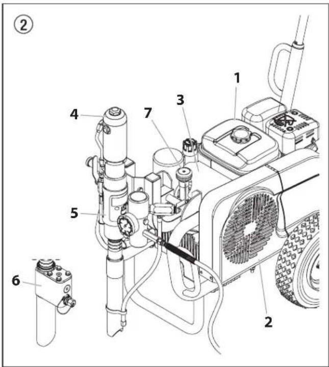
3.2 Functioning of the unit
The following section contains a brief description of the technical construction for better understanding of the function.
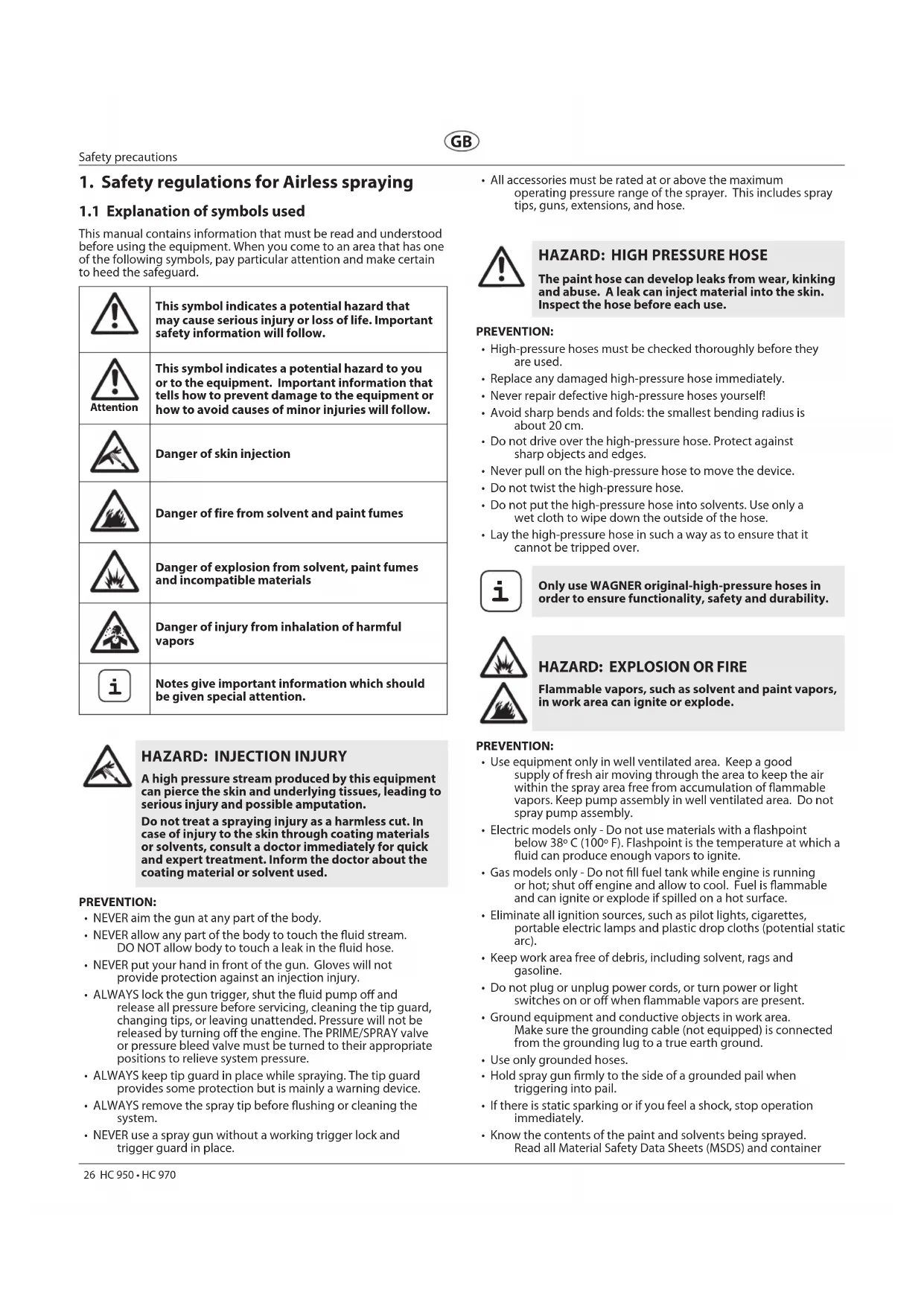
WAGNER HC 950 • 970 are high-pressure spraying units driven by either a gasoline engine or electric motor.
The gasoline engine or electric motor (fig. 2, item 1) drives the hydraulic pump (3) by means of a V-belt which is under the belt cover (2). Hydraulic oil flows to the hydraulic motor (4) and then moves the piston up and down in the material feed pump (5).
With devices HC 950-SSP and HC 970-SSP, the piston in the material feed pump moves a shovel valve (6). The shovel valve feeds high-viscosity coating materials.
The inlet valve is opened automatically by the upwards movement of the piston. The outlet valve is opened when the piston moves downward.
The coating material flows under high pressure through the high-pressure hose to the spray gun. When the coating material exits from the tip it atomises.
The pressure control valve (7) controls the volume and the operating pressure of the coating material.
3.3 Illustration legend for gasoline HC units
1 Spray gun
2 High-pressure hose
3 Gasoline engine
4 Extractable handle
5 V-belt under the belt cover
6 Return hose
7 Suction tube
8 High-pressure filter
9 Material feed pump — HC 950, HC 970
10 Material feed pump — HC 950-SSP, HC 970-SSP
11 Pressure gauge
12 Oil cup for separating oil (separating oil prevents increased wear and tear of the packings)
13 Ball valve: horizontal position – hydraulic motor switched off vertical position – hydraulic motor switched on
14 Handle for swiveling the material feed pump
15 Hydraulic motor
16 Relief valve handle: Turn left for circulation ○
Turn right for spray ≈π
17 Hydraulic oil pump
18 Pressure control knob
19 Oil measuring stick
3.4 Illustration of gasoline HC units
③
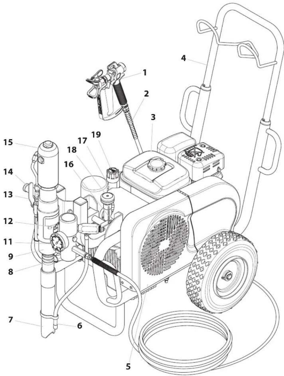
3.5 Illustration legend for electric HC units
1 Spray gun
2 High-pressure hose
3 Electric motor
4 ON/OFF switch
5 Control lamp that shows unit operational
6 Power cord
7 Extractable handle
8 V-belt under the belt cover
9 Return hose
10 Suction tube
11 High-pressure filter
12 Material feed pump — HC 950, HC 970
13 Material feed pump — HC 950-SSP, HC 970-SSP
14 Pressure gauge
15 Oil cup for separating oil (separating oil prevents increased wear and tear of the packings)
16 Ball valve: horizontal position – hydraulic motor switched off vertical position – hydraulic motor switched on
17 Handle for swiveling the material feed pump
18 Hydraulic motor
19 Relief valve handle: Turn left for circulation
Turn right for spray
20 Hydraulic oil pump
21 Pressure control knob
22 Oil measuring stick
3.6 Illustration of electric HC units
3.7 Technical data for gasoline HC units
| 3.7 Technical data for gasoline HC units | HC 950(0528500) | HC 950-SSP(0528502) | HC 970(0528508) | HC 970-SSP(0528506) |
| Gasoline engine, power | ||||
| 4.1 kW: * * | ||||
| 6 kW: * * | ||||
| Max. operating pressure | ||||
| 25 MPa (250 bar): * * * * | ||||
| Max. volume flow | ||||
| 8 l/min: * * | ||||
| 12 l/min: * * | ||||
| Volume flow at 12 MPa (120) bar | ||||
| 7.6 l/min: * * | ||||
| 11 l/min: * * | ||||
| Max. size of tip with a spray gun | ||||
| 0.052 inch - 1.30 mm: * * | ||||
| 0.056 inch - 1.42 mm: * * | ||||
| Fluid outlet fitting | ||||
| 3/8 inch - 9.5 mm: * | ||||
| 1/2 inch - 12.7 mm: * * * | ||||
| Max. temperature of the coating material | ||||
| 43°C: * * * * | ||||
| Max. Viscosity | ||||
| 50.000 mPa·s: * * | ||||
| 65.000 mPa·s: * * | ||||
| Filter insert (standard equipment) | ||||
| 0 Mesh: | * * * | * | ||
| Weight | ||||
| 76 kg | * * | |||
| 88 kg * * | ||||
| Hydraulic oil filling quantity | ||||
| 4.7 ISO 32: | * * * | * | ||
| Max. tire pressure | ||||
| 0.2 MPa (2 bar): | * * * | * | ||
| Special high-pressure hose | ||||
| DN 10 mm, 15 m, connection thread NPSM 3/8: | * | |||
| DN 13 mm, 15 m, connection thread NPSM 1/2: | * * * | |||
| Hose whip | ||||
| DN 10 mm, 2.5 m, connection thread NPSM 3/8: | * * * | |||
| Dimensions L x W x H | ||||
| 1185 x 955 x 655 mm: | * * | |||
| 1200 x 955 x 655 mm: | * * | |||
| Max.sound pressure level: | ||||
| 92 dB (A)* | * * | |||
| 98 dB (A)* | * * | |||
* Place of measurement: 1 m distance from unit and 1.60 m above reverberant floor, 120 bar (12 MPa) operating pressure.
3.8 Technical data for electric HC units
| 3.8 Technical data for electric HC units | HC 950(0528501) | HC 950-SSP(0528503) | HC 970(0528509) | HC 970-SSP(0528507) |
| Voltage | ||||
| 230 V~, 50 Hz: * * | ||||
| 400 V, 50 Hz, V3~: * * | ||||
| Fuse protection | ||||
| 16 A: * * * * | ||||
| Power cord | ||||
| 3 x 2.5 mm2 - 6 m: * * | ||||
| 5 x 2.5 mm2 - 6 m: * * | ||||
| Capacity | ||||
| 3.6 kW: * * | ||||
| 5.5 kW: * * | ||||
| Max operating pressure | ||||
| 25 MPa (250 bar): * * * * | ||||
| Maximum volume flow | ||||
| 6.6 l/min: * * | ||||
| 10 l/min: * * | ||||
| Volume flow at 12 MPa (120 bar) | ||||
| 5.2 l/min: * * | ||||
| 10 l/min: * * | ||||
| Max. size of tip with a spray gun | ||||
| 0.052 inch - 1.30 mm: * * | ||||
| 0.056 inch - 1.42 mm: * * | ||||
| Fluid outlet fitting | ||||
| 3/8 inch - 9.5 mm: | * | |||
| 1/2 inch - 12.7 mm: | * * * | |||
| Max. temperature of the coating material | ||||
| 43°C: | * * * * | |||
| Max. Viscosity | ||||
| 50.000 mPa·s: | * | * | ||
| 65.000 mPa·s: | * | * | ||
| Filter insert (standard equipment) | ||||
| 0 Mesh: | * * * * | |||
| Weight: | ||||
| 83 kg | * | |||
| 84.5 kg | * | |||
| 100 kg | * | |||
| 103 kg | * | |||
| Hydraulic oil filling quantity | ||||
| 4.7 ISO 32: | * * * * | |||
| Max. tire pressure | ||||
| 0.2 MPa (2 bar): | * * * * | |||
| Special high-pressure hose | ||||
| DN 10 mm, 15 m, connection thread NPSM 3/8: | * | |||
| DN 13 mm, 15 m, connection thread NPSM 1/2: | * * * | |||
| Hose whip | ||||
| DN 10 mm, 2,5 m, connection thread NPSM 3/8: | * * * | |||
| Dimensions L x W x H | ||||
| 1185 x 955 x 655 mm: | * * | |||
| 1200 x 955 x 655 mm: | * * | |||
| Max. sound pressure level: | ||||
| 80 dB (A)* | * * | |||
| 88 dB (A)* | * * | |||
* Place of measurement: 1 m distance from unit and 1.60 m above reverberant floor, 12 MPa (120 bar) operating pressure.
Operating Temperature
This equipment will operate correctly in its intended ambient, at a minimum between +10°C and +40°C.
Relative Humidity
The equipment will operate correctly within an environment at 50% RH, +40°C. Higher RH may be allowed at lower temperatures.
Measures shall be taken by the Purchaser to avoid the harmful effects of occasional condensation.
Altitude
This equipment will operate correctly up to 2100 m above mean sea level.
Transportation and Storage
This equipment will withstand, or has been protected against, transportation and storage temperatures of -25^ to +55^ and for short periods up to +70^ .
It has been packaged to prevent damage from the effects of normal humidity, vibration and shock.
3.9 Transport

Do not lift by cart handle when loading or unloading. Device is very heavy. Three-person lift is required.
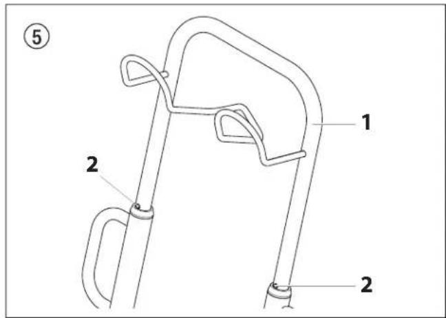
Handle
Pull out the handle (fig. 5, item 1) until it will come no further. Push in the snap buttons (2) on the sides of the handle and insert the handle.
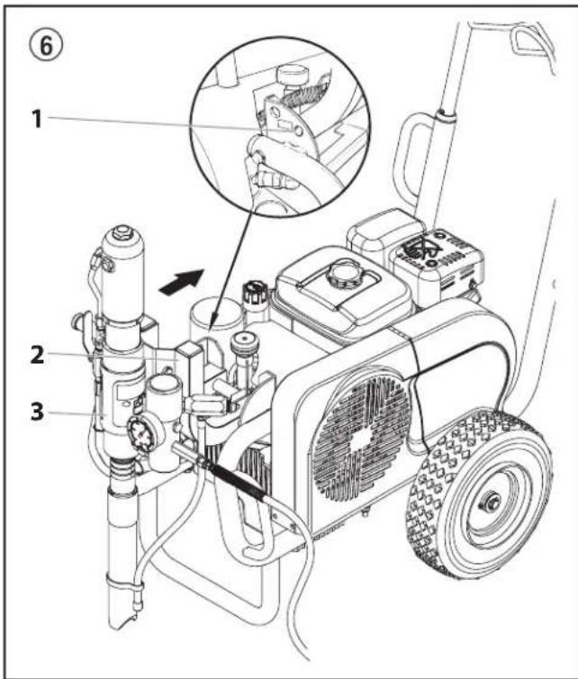
3.10 Transport in vehicle
Push locking pin (fig. 6, item 1) in the swivel mechanism (2) for the material feed pump (3) and swivel it to a horizontal position. Ensure that the locking pin locks.
Roll the high-pressure hose over the hose rack on the handle.
Secure the unit with a suitable fastening.
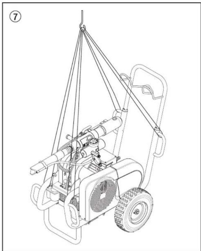
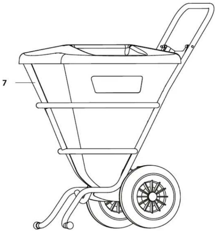
3.11 Crane transport
Hanging points for crane straps or ropes, see figure 7.
natural_image
Line drawing of a portable electric vehicle with attached suspension system (no text or symbols)4. Starting operation
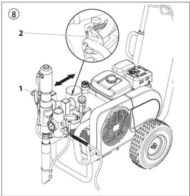
4.1 Changing the material feed pump position

Be careful, as the moving parts of the swivel mechanism can crush fingers and feet.
- Grip handle (fig. 8, item 1) with one hand.
- Push locking pin (2) with the other hand.
- Swivel material feed pump up or down to the desired position, until the locking pin (2) locks into the new position.
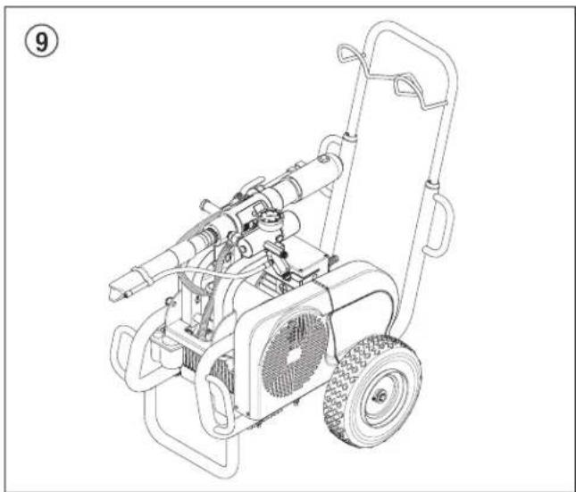
1. Transport position (fig. 9)
Transport unit only when the material feed pump is in the horizontal position.
Swiveling the material feed pump to a horizontal position also allows removal of the pump from the coating material container.
Ensure that the locking pin locks.
natural_image
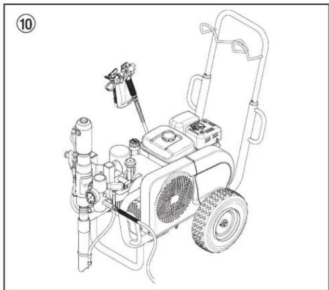
Line drawing of a mechanical lawn mower with visible blades and wheels (no text or symbols)2. Operating position I (fig. 10)
Swiveling the material feed pump to a vertical position allows the material feed pump to be immersed in the coating material container.
natural_image
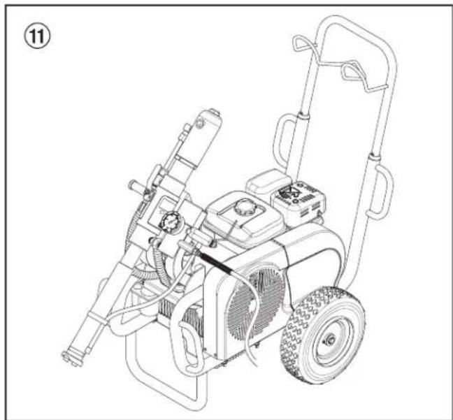
Line drawing of a mechanical power supply unit with hoses and valves (no text or symbols)3. Operating position II (fig. 11)
Swivel material feed pump to a slanted (45°) position if using the container suction system (accessory). In this position, there is open space under the material feed pump.
natural_image
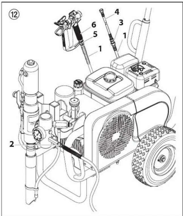
Line drawing of a portable power tool with attached fan and hose (no text or symbols)4.2 High-pressure hose, spray gun and separating oil
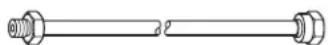
- Screw the high-pressure hose (fig. 12, item 1) onto the hose connection (2).
- Screw HC 950-SSP • HC 970 and HC 970-SSP double socket (3) into the high-pressure hose.
Screw on hose whip (4).
- Screw connection socket (5) to the spray gun (6).
- Screw spray gun with selected tip to the high-pressure hose or hose whip (4), depending on the model.
- Tighten union nuts at high-pressure hose and, depending on the model, at the hose whip to prevent coating material from leaking.
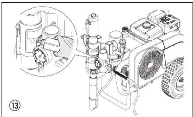
- Fill in EasyGlide (fig. 13). Do not fill in too much separating oil, i.e. ensure that no separating oil drips into the coating material container.

EasyGlide prevents increased wear and tear to the packings.
natural_image
Technical line drawing of a mechanical device with a magnified inset showing internal components (no text or symbols)4.3 Gasoline engine (gas units only)
- Fill in the supplied engine oil.
The gasoline engine is transported without engine oil.
The oil-level sensor prevents the engine from being started when the oil level is too low.
For oil grades and quantities please refer to the engine instructions.
- Fill the gasoline tank.
For information on the gasoline please refer to the engine instructions.
4.4 Connection to the mains (electric units only)

The connection must take place through a properly earthed two-pole and earth socket outlet.
Before connecting the unit to the mains supply, make sure that the line voltage matches the specifications on the unit's rating plate. The green indicator light will light up as soon as the mains plug has been connected.
4.5 Flushing preserving fluid during initial start-up
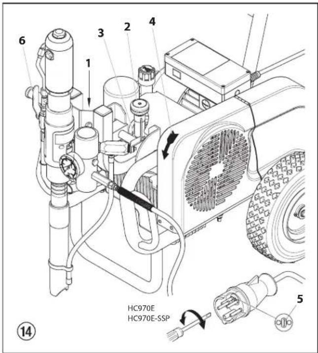
- Push locking pin (fig. 14, item 1) and swivel material feed pump to a container with suitable cleaning agent.
- Turn the pressure control knob (2) on the hydraulic pump to the left (pressure reduction) until it stops.
- Turn the relief valve handle (3) fully counterclockwise (Circulation).
- Start the engine or turn on the electric motor.
a. To start the gas engine, refer to the engine manual.
b. To start the electric motor:
- For HC 920 and HC 950 units, move the switch to "1" (ON).
- For HC 970 units, first set the switch to "Y" and then to "Δ" (ON).

The direction of the rotation of the pulley must correspond to the arrow (4) on the belt cover. If the belt is running opposite the direction of the arrow: Switch unit to "O" (OFF). Unplug power plug and turn the polarity changer (5) in the power plug by 180° with a screwdriver. Plug in power plug again.
- Move the hydraulic ball valve (6) on the material feed pump to its vertical position (open). This will switch on the hydraulic motor.
Hydraulic oil flows to the hydraulic motor of the material feed pump.
- Turn the pressure control knob (2) to the right (pressure increase) until cleaning agent exits the return hose.
- Turn relief valve handle (3) fully clockwise ( ^™ spray).
- Pull the trigger of the spray gun.
- Spray the cleaning agent from the unit into an open collecting container.
4.6 Taking the unit into operation with coating material

If the unit is located on a non-conductive surface (e.g. a wood floor), earth the unit with an earthing cable.
- Push locking pin (fig. 14, item 1) and swivel material feed pump into the coating material container.
- Turn the pressure control knob (2) on the hydraulic pump to the left (pressure reduction) until it stops.
- Turn the relief valve handle (3) fully counterclockwise (○Circulation).
- Start the engine or turn on the electric motor.
a. To start the gas engine, refer to the engine manual.
b. To start the electric motor: - For HC 950 units, move the switch to "1" (ON).
- For HC 970 units, first set the switch to "Y" and then to "Δ" (ON).

The direction of the rotation of the pulley must correspond to the arrow (4) on the belt cover. If the belt is running opposite the direction of the arrow: Switch unit to "O" (OFF). Unplug power plug and turn the polarity changer (5) in the power plug by 180° with a screwdriver. Plug in power plug again.
- Move the hydraulic ball valve (6) on the material feed pump to its vertical position (open). This will switch on the hydraulic motor.
Hydraulic oil flows to the hydraulic motor of the material feed pump. - Turn the pressure control knob (2) to the right (pressure increase) until coating material exits the return hose.
- Turn relief valve handle (3) fully clockwise ( ^27 spray).
- Pull the trigger of the spray gun, then set the desired operating pressure by means of the pressure control knob (2).
- The unit is ready to spray.
5. Spraying technique
Move the spray gun evenly during the spraying process. Otherwise the spray pattern will be uneven. Carry out the spray movement with the arm, not with the wrist. Observe a parallel distance of approx. 30 cm between the spray gun and the object of spraying. The lateral edge of the spray jet should not be too distinct. The spray edge should be gradual in order to facilitate overlapping of the next coat. Always move the spray gun parallel and at an angle of 90° to the surface to be coated in order to minimize the paint mist.

If very sharp edges result or if there are streaks in the spray jet – increase the operating pressure or dilute the coating material.
6. Handling the high-pressure hose
The unit is equipped with a high-pressure hose specially suited for piston pumps.

Danger of injury through leaking high-pressure hose. Replace any damaged high-pressure hose immediately.
Never repair defective high-pressure hoses yourself!
The high-pressure hose is to be handled with care. Avoid sharp bends and folds: the smallest bending radius is about 20 cm. Do not drive over the high-pressure hose. Protect against sharp objects and edges.
Never pull on the high-pressure hose to move the device.
Make sure that the high-pressure hose cannot twist. This can be avoided by using a Wagner spray gun with a swivel joint and a hose system.

When using the high-pressure hose while working on scaffolding, it is best to always guide the hose along the outside of the scaffolding.
The risk of damage rises with the age of the high-pressure hose. Wagner recommends replacing high-pressure hoses after 6 years.
Use only WAGNER original-high-pressure hoses in order to ensure functionality, safety and durability.
7. Interruption of work
- Move the hydraulic ball valve on the material feed pump to its horizontal position (closed).
Flow of hydraulic oil to hydraulic motor of material feed pump is interrupted. - Turn the relief valve handle (3) fully counterclockwise (○Circulation).
- Turn off the gasoline engine or electric motor.
- Pull the trigger of the spray gun in order to release the pressure from the high-pressure hose and spray gun.
- Secure the spray gun, refer to the operating manual of the spray gun.
- If a standard tip is to be cleaned, see page 43, point 11.2.
If a non-standard tip is installed, proceed according to the relevant operating manual. - Leave the suction tube immersed in the coating material or immerse it in the corresponding cleaning agent.

If fast-drying or two-component coating material is used, ensure that the unit is rinsed with a suitable cleaning agent within the processing time.
8. Cleaning the unit (shutting down)
A clean state is the best method of ensuring operation without problems. After you have finished spraying, clean the unit. Under no circumstances may any remaining coating material dry and harden in the unit.
The cleaning agent used for cleaning (only with an ignition point above 21 °C) must be suitable for the coating material used.
- Secure the spray gun, refer to the operating manual of the spray gun.
Clean and remove tip.
For a standard tip, refer to page 43, point 11.2.
If a non-standard tip is installed, proceed according to the relevant operating manual.
- Push locking pin and swivel material feed pump out of coating material.
- Pull the trigger of the spray gun in order to pump the remaining coating material from the suction tube, high-pressure hose and the spray gun into an open container.

Attention
The container must be earthed in case of coating materials which contain solvents.

Caution! Do not pump or spray into a container with a small opening (bunghole)! Refer to the safety regulations.
- Push locking pin and swivel material feed pump to a container with suitable cleaning agent.
- Turn the relief valve handle fully counterclockwise (○ Circulation).
- Pump a suitable cleaning agent in the circuit for a few minutes.
- Turn relief valve handle fully clockwise ( ^27 spray).
- Pump the remaining cleaning agent into an open container until the unit is empty.
- Turn the relief valve handle fully counterclockwise (○Circulation).
- Move the hydraulic ball valve on the material feed pump to its horizontal position (closed).
- Turn off the gasoline engine or electric motor.
8.1 Cleaning the unit from the outside

Gasoline units — Switch off the gasoline engine and let it cool down.
Electric units — Unplug the mains plug from the socket.
Danger of short-circuits through penetrating water. Never spray down the unit with high-pressure or high-pressure steam cleaners.

Do not put the high-pressure hose into solvents. Use only a wet cloth to wipe down the outside of the hose.
Wipe the unit off with a cloth soaked in a suitable cleaning agent.
8.2 Cleaning the high-pressure filter
Clean the filter cartridge regularly.
A soiled or clogged high-pressure filter can cause a poor spray pattern or a clogged tip.
Disassembly
- Move the hydraulic ball valve on the material feed pump to its horizontal position (closed).
Flow of hydraulic oil to hydraulic motor of material feed pump is interrupted. - Turn the relief valve handle fully counterclockwise (○ Circulation).
- Turn off the gasoline engine or electric motor.
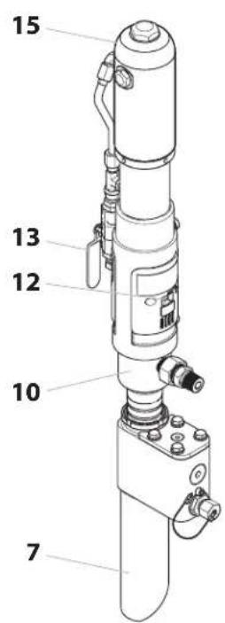
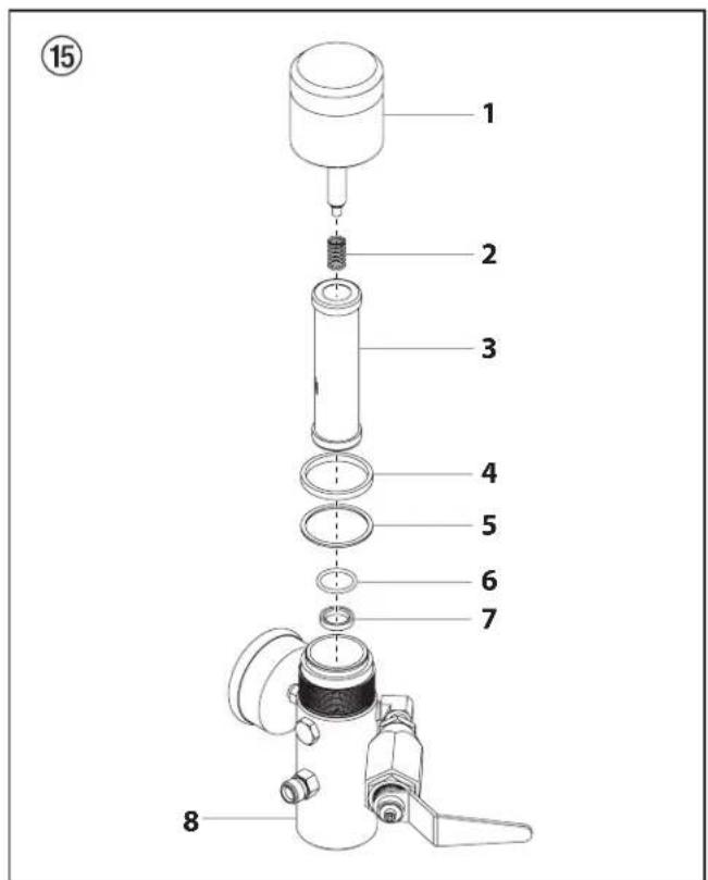
- Unscrew the housing cover (fig. 15, item 1).
- Pull filter cartridge (3) out of housing (8).
- Clean the pressure spring (2) and filter cartridge (3) with an appropriate cleaning agent, clean the inside of the housing (8) and housing cover (1).
- Check ball in the filter cartridge (3) for wear and replace filter cartridge, if necessary.
- If ball in filter cartridge (3) is thoroughly worn, aremove O-ring (6) and valve seat (7). Replace worn valve seat, if necessary.
9. Always replace O-ring (6) after removal.
- Pull off pressure spring (2) from housing cover (1). Measure length of pressure spring, and replace if shorter than 19 mm.
Assembly
- Insert valve seat (7) with the ball seat surface facing up into the housing (8).
- Insert O-ring (6) into the housing (8).
- Insert filter cartridge (3).
- Place thin seal (5) on threaded section of housing (8).
- Place thick seal (4) on top of thin seal (5).
- Slide pressure spring (2) onto housing cover pin (2).
- Screw on housing cover (1) and tighten by hand.
8.3 Cleaning Airless spray gun
- Rinse Airless spray gun with an appropriate cleaning agent.
- Clean tip thoroughly with appropriate cleaning agent so that no coating material residue remains.
- Thoroughly clean the outside of the Airless spray gun.
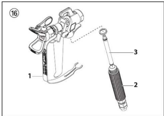
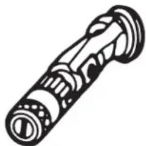
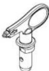
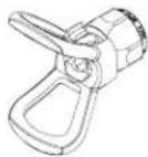
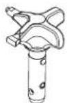
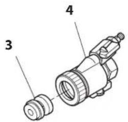
Intake filter in Airless spray gun (fig. 16)
Dismounting
- Pull protective guard (1) forward vigorously.
- Screw handle (2) out of the gun housing. Remove intake filter (3).
- Intake filter congested or defective – replace.
Mounting
- Place intake filter (3) with the long cone into the gun housing.
- Screw handle (2) into the gun housing and tight en.
- Snap in protective guard (1).
9.1 Gasoline engine
| Type of malfunction | Possible cause | Measures for eliminating the malfunction |
| A. Gasoline engine does not start up | 1. No gasoline.2. ON/OFF switch to OFF.3. Gasoline cock closed.4. Engine problem.5. Engine defective.6. Oil level insufficient. | 1. Fill the gasoline tank.2. Move the switch to ON.3. Open the gasoline cock.4. Please refer to the engine instructions.5. Bring to the Honda service point.6. Top off oil. |
9.2 Electric Motor
| Type of malfunction | Possible cause | Measures for eliminating the malfunction |
| A. Unit does not start | 1. Indicator light does not indicate unit has power.2. The unit has switched off automatically because of an overload. | 1. Check power supply.2. Wait 2 – 3 minutes, then turn the unit back on. |
| B. HC 970 units:Piston rod in the material feed pump is not moving up and down. | 1. Direction of the rotation of the electric motor is incorrect | 1. Turn the polarity changer in the power plug 180°. |
9.3 Hydraulic motor
| Type of malfunction | Possible cause | Measures for eliminating the malfunction |
| A. Hydraulic motor stuck in the lower position. | 1. Outlet valve seat in the material feed pump is loose.2. Reversing valve in the hydraulic motor is stuck or the upper or lower hexagonal nut on the valve rod has become loose. | 1. Ball valve on the material feed pump – lever position vertical. Screw out sealing screw on hydraulic motor. Press down reversing valve on hydraulic motor. Remount sealing screw. Start unit. The piston rod moves upward and then gets stuck in the lower position. The cause is a loose outlet valve seat.2. Take unit to a Wagner authorized service center. |
| B. Hydraulic motor stuck in the upper position. | 1. Reversing valve is stuck.2. Pressure spring on valve rod is broken.3. Pressure spring stop on valve rod is broken.4. Air in the hydraulic motor. | 1. Take unit to a Wagner authorized service center.2. Take unit to a Wagner authorized service center.3. Take unit to a Wagner authorized service center.4. Turn back pressure control knob.Vent air at low pressure during a 5 – 10 minute endurance run. Do not let the material feed pump run dry.Check for leaks:Loose connections on hydraulic oil tankLoose connections on the hydraulic oil pumpLoose hydraulic oil hose connectionsLevel of oil in hydraulic tank is too low |
| 5. Air in the material feed pump. | 5. Ball valve on the material feed pump – lever position vertical. Screw out sealing screw on hydraulic motor. Press down reversing valve on hydraulic motor.Remount sealing screw. Start unit. Prevent the material feed pump from sucking up air. | |
| C. Low pressure. The piston rod moves correctly in the downward stroke, but the upward stroke is sluggish. The outside of the hydraulic motor is very hot. | 1. Faulty piston packing in hydraulic motor.2. Piston rod is broken. | 1. Take unit to a Wagner authorized service center.2. Take unit to a Wagner authorized service center. |
| D. Low pressure. The outside of the hydraulic motor becomes very hot when stroking upward and downward. | 1. Middle O-ring on reversing valve is faulty.2. Packings in the material feed pump are worn. | 1. Take unit to a Wagner authorized service center.2. Replace |
9.4 Material feed pump
| Type of malfunction | Possible cause | Measures for eliminating the malfunction |
| A. A sufficient amount of coating material is ejected only with an upward stroke, or upward motion of the piston rod is slow and downward motion is fast | 1. Inlet valve is leaky due to impurities or wear.2. Coating material viscosity is too high, preventing it from being sucked up. | 1. Clean and check the inlet valve housing. Insert ball and fill with water; if leaky, replace ball.2. Thin out according to the manufacturer's instructions. |
| B. A sufficient amount of coating material is ejected only with a downward stroke, or downward motion of the piston rod is slow and upward motion is fast. | 1. Outlet valve leaky.2. Lower packing is worn. | 1. Dismantle and check outlet valve seat. Insert ball and fill with water; if leaky, replace ball.2. Replace. |
| C. Piston rod moves up and down quickly. | 1. Suction tube projects over the fluid level and sucks in air.2. Coating material viscosity is too high, preventing it from being sucked up.3. Ball in inlet valve housing is stuck. | 1. Refill the coating material2. Thin out the coating material according to manufacturer's instructions.3. Vent air from material feed pump and turn the relief valve knob to the left (○ Circulation). |
| D. Piston rod moves up and down slowly when the spray gun is closed. | 1. Loose connections.2. Relief valve is not closed completely.3. Relief valve worn.4. Lower packing worn.5. Ball in inlet valve housing and ball in outlet valve seat are not sealing properly. | 1. Dismantle inlet valve housing, clean ball and valve seat. Check all connections between the material feed pump and spray gun.2. Turn relief valve handle (3) fully clockwise (♂ spray).3. Replace4. If the measures described above do not help, replace lower packing.5. Dismantle inlet valve housing and outlet valve seat. Clean balls and valve seats. |
| E. Not enough pressure to the spray gun. | 1. Tip is worn.2. Filter cartridge in high-pressure filter is clogged.3. High-pressure hose is too long. | 1. Replace2. Clean or replace the filter cartridge.3. Reduce length. |
| F. Piston rod sputters when stroking upward or downward. | 1. Solvent has made the upper packing expand. | 1. Replace upper packing. |
10. Servicing
10.1 General servicing
The unit should be serviced once a year by the Wagner Service.
- For servicing of the gasoline engine, refer to the engine instructions.
- Check the high-pressure hoses for damage.
- Check the inlet and outlet vents for wear.
- Check oil level in hydraulic oil tank.
- Carry out an oil change if necessary.
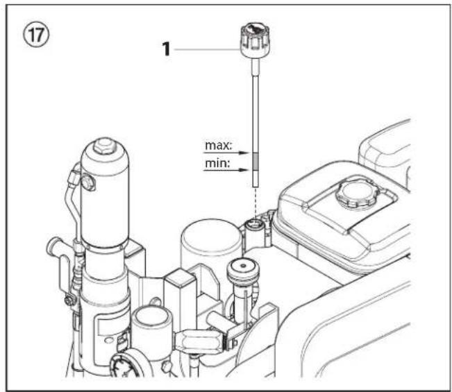
10.2 Checking the oil level in the hydraulic oil tank

Gasoline units — Check oil level daily.

Electric units — Switch off unit "O" (OFF). Remove the mains plug from the socket.
- Turn oil measuring stick (fig. 17, item 1) to the left and pull out.
- The oil level should be visible between the marking (see arrows) on the oil measuring stick.
- If necessary, refill oil. For information on the oil grade, refer to the oil change section, chapter 10.3.
10.3 Oil and oil filter change of the hydraulic oil pump
Carry out oil and oil filter change once every 12 months.

Danger to the environment
Do not dispose of waste oil into the sewer or soil. Polluting the ground water is a crime. Waste oil can be returned where hydraulic oil is bought.

Carry out an oil change while the unit is still warm from operation.

Electric units — Switch off unit "O" (OFF). Remove the mains plug from the socket.
- Turn off the gasoline engine or electric motor.
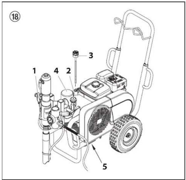
- Move the hydraulic ball valve (fig. 18, item 1) on the material feed pump to its vertical position (open).
- Remove the screws on the hydraulic oil pump cover (2) and remove cover.
- Turn oil measuring stick (3) to the left and pull out.
- Screw out oil filter (4) with a strap spanner and replace.
- Screw out sealing screw (5) under the hydraulic oil tank. Drain the waste oil.
- Replace the sealing screw into the hydraulic oil tank.
- Fill in 4.7 liters of ESSO ISO 32 hydraulic oil.

When oil is filled in, air can enter the hydraulic system. Therefore, the system must be vented.
- Let the unit run for at least five minutes at low pressure to automatically bleed the air from the hydraulic system.
10.4 High-pressure hose
Inspect the high-pressure hose visually for any notches or bulges, in particular at the transition in the fittings. It must be possible to turn the union nuts freely.

The risk of damage rises with the age of the high-pressure hose. Wagner recommends replacing high-pressure hoses after 6 years.
11. Appendix
11.1 Selection of tip
To achieve faultless and rational working, the selection of the tip is of the greatest importance.
In many cases the correct tip can only be determined by means of a spraying test.
Some rules for this:
The spray jet must be even.
If streaks appear in the spray jet the spraying pressure is either too low or the viscosity of the coating material to high.
Remedy: Increase pressure or dilute coating material. Each pump conveys a certain quantity in proportion to the size of the tip:
The following principle is valid: large tip = low pressure
small tip = high pressure
There is a large range of tips with various spraying angles.
11.2 Servicing and cleaning of Airless hard-metal tips
Standard tips
If a different tip type has been fitted, then clean it according to manufacturer's instructions.
The tip has a bore processed with the greatest precision. Careful handling is necessary to achieve long durability. Do not forget the fact that the hard-metal insert is brittle! Never throw the tip or handle with sharp metal objects.
The following points must be observed to keep the tip clean and ready for use:
- Turn the relief valve handle fully counterclockwise ( Circulation).
- Switch off the gasoline engine.
- Dismount the tip from the spray gun.
- Place tip in an appropriate cleaning agent until all coating material residue is dissolved.
- If there is pressure air, blow out tip.
- Remove any residue by means of a sharp wooden rod (toothpick).
- Check the tip with the help of a magnifying glass and, if necessary, repeat points 4 to 6.
11.3 Spray gun accessories
natural_image
Illustration of a mechanical device with no visible text or symbolsFlat jet adjusting tip
up to 250 bar (25 MPa
| Tip marking | Bore mm | Spray width at about 30 cm removal of spray object Pressure 100 bar (10 MPa) | Use | Flat jet adjusting tip Order No. |
| 15 0.13 | - 0.46 5 - 35 cm | Paints 0999 057 | ||
| 20 0.18 | - 0.48 5 - 50 cm | Paints, fillers 0999 053 | ||
| 28 0.28 | - 0.66 8 - 55 cm | Paints, dispersions 0999 054 | ||
| 41 0.43 | - 0.88 | 10 - 60 cm | Rust protection paints - dispersions | 0999 055 |
| 49 | 0.53 - 1.37 | 10 - 40 cm | Large-area coats | 0999 056 |
Contact protection
for the flat jet adjustment tip
Order No. 0097 294
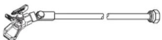
Tip extension with slewable knee joint (without tip)
Length: 100 cm Order no. 0096 015
Length: 200 cm Order no. 0096 016
Length: 300 cm Order no. 0096 017
Tip extension
15 cm, F-thread, Order no. 0556 051
30 cm, F-thread, Order no. 0556 052
45 cm, F-thread, Order no. 0556 053
60 cm, F-thread, Order no. 0556 054
15 cm, G-thread, Order no. 0556 074
30 cm, G-thread, Order no. 0556 075
45 cm, G-thread, Order no. 0556 076
60 cm, G-thread, Order no. 0556 077
11.4 Airless tip table
Wagner
TradeTip 3 tip
up to 270 bar
(27 MPa)
without tip
F thread (11/16 - 16 UN)
for Wagner spray guns
Order no. 0289391
without tip
G thread (7/8 - 14 UN)
for Graco/Titan spray guns
Order no. 0289390

All of the tips in the table below are supplied together with the appropriate gun filter.
| Application Tip marking Spray | angle | Bore inch / mm | Spraying width mm 1) | Gun filter Order | no. | |
| Water-thinnable and solvent-based paints and varnishes, oils, separating agents | 107 | 10^ | 0.007 / 0.18 | 100 | red | 0553107 |
| 207 | 20^ | 0.007 / 0.18 | 120 | red | 0553207 | |
| 307 | 30^ | 0.007 / 0.18 | 150 | red | 0553307 | |
| 407 | 40^ | 0.007 / 0.18 | 190 | red | 0553407 | |
| 109 | 10^ | 0.009 / 0.23 | 100 | red | 0553109 | |
| 209 | 20^ | 0.009 / 0.23 | 120 | red | 0553209 | |
| 309 | 30^ | 0.009 / 0.23 | 150 | red | 0553309 | |
| 409 | 40^ | 0.009 / 0.23 | 190 | red | 0553409 | |
| 509 | 50^ | 0.009 / 0.23 | 225 | red | 0553509 | |
| 609 | 60^ | 0.009 / 0.23 | 270 | red | 0553609 | |
| Synthetic-resin paintsPVC paints | 111 | 10^ | 0.011 / 0.28 | 100 | red | 0553111 |
| 211 | 20^ | 0.011 / 0.28 | 120 | red | 0553211 | |
| 311 | 30^ | 0.011 / 0.28 | 150 | red | 0553311 | |
| 411 | 40^ | 0.011 / 0.28 | 190 | red | 0553411 | |
| 511 | 50^ | 0.011 / 0.28 | 225 | red | 0553511 | |
| 611 | 60^ | 0.011 / 0.28 | 270 | red | 0553611 | |
| Paints, primersFillers | 113 | 10^ | 0.013 / 0.33 | 100 | red | 0553113 |
| 213 | 20^ | 0.013 / 0.33 | 120 | red | 0553213 | |
| 313 | 30^ | 0.013 / 0.33 | 150 | red | 0553313 | |
| 413 | 40^ | 0.013 / 0.33 | 190 | red | 0553413 | |
| 513 | 50^ | 0.013 / 0.33 | 225 | red | 0553513 | |
| 613 | 60^ | 0.013 / 0.33 | 270 | red | 0553613 | |
| 813 | 80^ | 0.013 / 0.33 | 330 | red | 0553813 | |
| FillersRust protection paints | 115 | 10^ | 0.015 / 0.38 | 100 | yellow | 0553115 |
| 215 | 20^ | 0.015 / 0.38 | 120 | yellow | 0553215 | |
| 315 | 30^ | 0.015 / 0.38 | 150 | yellow | 0553315 | |
| 415 | 40^ | 0.015 / 0.38 | 190 | yellow | 0553415 | |
| 515 | 50^ | 0.015 / 0.38 | 225 | yellow | 0553515 | |
| 615 | 60^ | 0.015 / 0.38 | 270 | yellow | 0553615 | |
| 715 | 70^ | 0.015 / 0.38 | 300 | yellow | 0553715 | |
| 815 | 80^ | 0.015 / 0.38 | 330 | yellow | 0553815 | |
| Rust protection paintsLatex paintsDispersions | 117 | 10^ | 0.017 / 0.43 | 100 | white | 0553117 |
| 217 | 20^ | 0.017 / 0.43 | 120 | white | 0553217 | |
| 317 | 30^ | 0.017 / 0.43 | 150 | white | 0553317 | |
| 417 | 40^ | 0.017 / 0.43 | 190 | white | 0553417 | |
| 517 | 50^ | 0.017 / 0.43 | 225 | white | 0553517 | |
| 617 | 60^ | 0.017 / 0.43 | 270 | white | 0553617 | |
| 717 | 70^ | 0.017 / 0.43 | 300 | white | 0553717 | |
| 817 | 80^ | 0.017 / 0.43 | 330 | white | 0553817 | |
| Rust protection paintsLatex paintsDispersions | 219 | 20^ | 0.019 / 0.48 | 120 | white | 0553219 |
| 319 | 30^ | 0.019 / 0.48 | 150 | white | 0553319 | |
| 419 | 40^ | 0.019 / 0.48 | 190 | white | 0553419 | |
| 519 | 50^ | 0.019 / 0.48 | 225 | white | 0553519 | |
| 619 | 60^ | 0.019 / 0.48 | 270 | white | 0553619 | |
| 719 | 70^ | 0.019 / 0.48 | 300 | white | 0553719 | |
| 819 | 80^ | 0.019 / 0.48 | 330 | white | 0553819 | |
| 919 | 90^ | 0.019 / 0.48 | 385 | white | 0553919 | |
| Flame retardant 221 | 20^ | 0.021 / 0.53 | 120 | white | 0553221 | |
| 321 | 30^ | 0.021 / 0.53 | 150 | white | 0553321 | |
| 421 | 40^ | 0.021 / 0.53 | 190 | white | 0553421 | |
| 521 | 50^ | 0.021 / 0.53 | 225 | white | 0553521 | |
| 621 | 60^ | 0.021 / 0.53 | 270 | white | 0553621 | |
| 721 | 70^ | 0.021 / 0.53 | 300 | white | 0553721 | |
| 821 | 80^ | 0.021 / 0.53 | 330 | white | 0553821 |
1) Spray width at about 30 cm to the object and 100 bar (10 MPa) pressure with synthetic-resin paint 20 DIN seconds.
| Application Tip marking Spray | angle | Bore inch / mm | Spraying width mm 1) | Gun filter Order | no. | |
| Roof coatings 223 | 20^ | 0.023 / 0.58 | 120 | white | 0553223 | |
| 323 | 30^ | 0.023 / 0.58 | 150 | white | 0553323 | |
| 423 | 40^ | 0.023 / 0.58 | 190 | white | 0553423 | |
| 523 | 50^ | 0.023 / 0.58 | 225 | white | 0553523 | |
| 623 | 60^ | 0.023 / 0.58 | 270 | white | 0553623 | |
| 723 | 70^ | 0.023 / 0.58 | 300 | white | 0553723 | |
| 823 | 80^ | 0.023 / 0.58 | 330 | white | 0553823 | |
| Thick-film materials, Corrosion protection Spray filler | 225 | 20^ | 0.025 / 0.64 | 120 | white | 0553225 |
| 325 | 30^ | 0.025 / 0.64 | 150 | white | 0553325 | |
| 425 | 40^ | 0.025 / 0.64 | 190 | white | 0553425 | |
| 525 | 50^ | 0.025 / 0.64 | 225 | white | 0553525 | |
| 625 | 60^ | 0.025 / 0.64 | 270 | white | 0553625 | |
| 725 | 70^ | 0.025 / 0.64 | 300 | white | 0553725 | |
| 825 | 80^ | 0.025 / 0.64 | 330 | white | 0553825 | |
| 227 | 20^ | 0.027 / 0.69 | 120 | white | 0553227 | |
| 327 | 30^ | 0.027 / 0.69 | 150 | white | 0553327 | |
| 427 | 40^ | 0.027 / 0.69 | 190 | white | 0553427 | |
| 527 | 50^ | 0.027 / 0.69 | 225 | white | 0553527 | |
| 627 | 60^ | 0.027 / 0.69 | 270 | white | 0553627 | |
| 827 | 80^ | 0.027 / 0.69 | 330 | white | 0553827 | |
| 229 | 20^ | 0.029 / 0.75 | 120 | white | 0553229 | |
| 329 | 30^ | 0.029 / 0.75 | 150 | white | 0553329 | |
| 429 | 40^ | 0.029 / 0.75 | 190 | white | 0553429 | |
| 529 | 50^ | 0.029 / 0.75 | 225 | white | 0553529 | |
| 629 | 60^ | 0.029 / 0.75 | 270 | white | 0553629 | |
| 231 | 20^ | 0.031 / 0.79 | 120 | white | 0553231 | |
| 331 | 30^ | 0.031 / 0.79 | 150 | white | 0553331 | |
| 431 | 40^ | 0.031 / 0.79 | 190 | white | 0553431 | |
| 531 | 50^ | 0.031 / 0.79 | 225 | white | 0553531 | |
| 631 | 60^ | 0.031 / 0.79 | 270 | white | 0553631 | |
| 731 | 70^ | 0.031 / 0.79 | 300 | white | 0553731 | |
| 831 | 80^ | 0.031 / 0.79 | 330 | white | 0553831 | |
| 233 | 20^ | 0.033 / 0.83 | 120 | white | 0553233 | |
| 333 | 30^ | 0.033 / 0.83 | 150 | white | 0553333 | |
| 433 | 40^ | 0.033 / 0.83 | 190 | white | 0553433 | |
| 533 | 50^ | 0.033 / 0.83 | 225 | white | 0553533 | |
| 633 | 60^ | 0.033 / 0.83 | 270 | white | 0553633 | |
| 235 | 20^ | 0.035 / 0.90 | 120 | white | 0553235 | |
| 335 | 30^ | 0.035 / 0.90 | 150 | white | 0553335 | |
| 435 | 40^ | 0.035 / 0.90 | 190 | white | 0553435 | |
| 535 | 50^ | 0.035 / 0.90 | 225 | white | 0553535 | |
| 635 | 60^ | 0.035 / 0.90 | 270 | white | 0553635 | |
| 735 | 70^ | 0.035 / 0.90 | 300 | white | 0553735 | |
| 439 | 40^ | 0.039 / 0.99 | 190 | white | 0553439 | |
| 539 | 50^ | 0.039 / 0.99 | 225 | white | 0553539 | |
| 639 | 60^ | 0.039 / 0.99 | 270 | white | 0553639 | |
| Heavy duty applications 243 | 20^ | 0.043 / 1.10 | 120 | green | 0553243 | |
| 443 | 40^ | 0.043 / 1.10 | 190 | green | 0553443 | |
| 543 | 50^ | 0.043 / 1.10 | 225 | green | 0553543 | |
| 643 | 60^ | 0.043 / 1.10 | 270 | green | 0553643 | |
| 445 | 40^ | 0.045 / 1.14 | 190 | green | 0553445 | |
| 545 | 50^ | 0.045 / 1.14 | 225 | green | 0553545 | |
| 645 | 60^ | 0.045 / 1.14 | 270 | green | 0553645 | |
| 451 | 40^ | 0.051 / 1.30 | 190 | green | 0553451 | |
| 551 | 50^ | 0.051 / 1.30 | 225 | green | 0553551 | |
| 651 | 60^ | 0.051 / 1.30 | 270 | green | 0553651 | |
| 252 | 20^ | 0.052 / 1.32 | 120 | green | 0553252 | |
| 455 | 40^ | 0.055 / 1.40 | 190 | green | 0553455 | |
| 555 | 50^ | 0.055 / 1.40 | 225 | green | 0553555 | |
| 655 | 60^ | 0.055 / 1.40 | 270 | green | 0553655 | |
| 261 | 20^ | 0.061 / 1.55 | 120 | green | 0553261 | |
| 461 | 40^ | 0.061 / 1.55 | 190 | green | 0553461 | |
| 561 | 50^ | 0.061 / 1.55 | 225 | green | 0553561 | |
| 661 | 60^ | 0.061 / 1.55 | 270 | green | 0553661 | |
| 263 | 20^ | 0.063 / 1.60 | 120 | green | 0553263 | |
| 463 | 40^ | 0.063 / 1.60 | 190 | green | 0553463 | |
| 565 | 50^ | 0.065 / 1.65 | 225 | green | 0553565 | |
| 665 | 60^ | 0.065 / 1.65 | 270 | green | 0553665 | |
| 267 | 20^ | 0.067 / 1.70 | 120 | green | 0553267 | |
| 467 | 40^ | 0.067 / 1.70 | 190 | green | 0553467 |
1) Spray width at about 30 cm to the object and 100 bar (10 MPa) pressure with synthetic-resin paint 20 DIN seconds.
11.5 2Speed Tip table
The innovative changeover nozzle from WAGNER combines two nozzle cores into one nozzle.
2 Speed Tip holder
Order no. 0271065
Tip table
| Object size Painting material | |||
| Lacquer (L) Emulsion (D) Filler (S) | |||
| Small | D5Nozzles: 111 / 415Order no. 0271 062 | S5Nozzles: 225 / 629Order no. 0271 064 | |
| D7Nozzles: 113 / 417Order no. 0271 063 | |||
| L10Nozzles: 208 / 510Order no. 0271 042 | D10Nozzles: 111 / 419Order no. 0271 045 | S10Nozzles: 527 / 235Order no. 0271 049 | |
| Medium | L20Nozzles: 210 / 512Order no. 0271 043 | D20Nozzles: 115 / 421Order no. 0271 046 | S20Nozzles: 539 / 243Order no. 0271 050 |
| Large | L30Nozzles: 212 / 514Order no. 0271 044 | D30Nozzles: 115 / 423Order no. 0271 047 | S30Nozzles: 543 / 252Order no. 0271 051 |
| X-Large | D40Nozzles: 117 / 427Order no. 0271 048 | ||
| Recommended gun filter red white | - | ||
A J. Wagner Ges.m.b.H. Ottogasse 2/20 2333 Leopoldsdorf Österreich Tel. +43/ 2235 / 44 158 Telefax +43/ 2235 / 44 163 office@wagner-group.at
DK Wagner Spraytech Scandinavia A/S Helgeshøj Allé 28 2630 Taastrup Denmark Tel. +45 43 27 18 18 Telefax +45 43 43 05 28 wagner@wagner-group.dk
GB Wagner Spraytech (UK) Limited The Coach House 2 Main Road Middleton Cheney OX17 2ND Great Britain UK-Helpline 01295 714200 Fax 01295 710100 enquiries@wagnerspraytech.co.uk
B WSB Finishing Equipment Veilinglaan 56-58 1861 Meise-Wolvertem Belgium Tel. +32/2/269 46 75 Telefax +32/2/269 78 45 info@wagner-wsb.nl

natural_image
Line drawing of a portable electric water heater with attached pump and fan (no text or symbols)④
natural_image
Line drawing of a mechanical pump or lift system with attached motors and suspension cables (no text or symbols)4. Mise en service
1. Position de transport (fig. 9)
natural_image
Line drawing of a manual lawn mower with visible blades and wheels (no text or symbols)natural_image
Technical line drawing of a portable electric water heater with attached pump and fan (no text or symbols)natural_image
Line drawing of a mechanical power tool with attached motors and wheels (no text or symbols)natural_image
Technical line drawing of a mechanical device with pipes and control panel, showing internal components and a magnified inset (no text or symbols)natural_image
Illustration of a mechanical device with no visible text or symbols2 Speed Tip support Réf. No. 0271065
Tableau des buses
| Taille de chantiers Produits applicables | |||
| Laque (L) Peinture (D) Enduit (S) | |||
| Petit | D5Buse: 111 / 415Réf. No. 0271 062 | S5Buse: 225 / 629Réf. No. 0271 064 | |
| D7Buse: 113 / 417Réf. No. 0271 063 | |||
| L10Buse: 208 / 510Réf. No. 0271 042 | D10Buse: 111 / 419Réf. No. 0271 045 | S10Buse: 527 / 235Réf. No. 0271 049 | |
| Moyen | L20Buse: 210 / 512Réf. No. 0271 043 | D20Buse: 115 / 421Réf. No. 0271 046 | S20Buse: 539 / 243Réf. No. 0271 050 |
| Grand | L30Buse: 212 / 514Réf. No. 0271 044 | D30Buse: 115 / 423Réf. No. 0271 047 | S30Buse: 543 / 252Réf. No. 0271 051 |
| Très grand | D40Buse: 117 / 427Réf. No. 0271 048 | ||
| Tamis de crosse recommandé rouge | blanc - | ||
A J. Wagner Ges.m.b.H. Ottogasse 2/20 2333 Leopoldsdorf Österreich Tel. +43/ 2235 / 44 158 Telefax +43/ 2235 / 44 163 office@wagner-group.at
DK Wagner Spraytech Scandinavia A/S Helgeshøj Allé 28 2630 Taastrup Denmark Tel. +45 43 27 18 18 Telefax +45 43 43 05 28 wagner@wagner-group.dk
GB Wagner Spraytech (UK) Limited The Coach House 2 Main Road Middleton Cheney OX17 2ND Great Britain UK-Helpline 01295 714200 Fax 01295 710100 enquiries@wagnerspraytech.co.uk
B WSB Finishing Equipment Veilinglaan 56-58 1861 Meise-Wolvertem Belgium Tel. +32/2/269 46 75 Telefax +32/2/269 78 45 info@wagner-wsb.nl

natural_image
Line drawing of a portable electric water heater with attached pump and fan (no text or symbols)④
natural_image
Line drawing of a mechanical pump or lift system with attached motors and suspension cables (no text or symbols)natural_image
Line drawing of a portable lawn mower with visible blades and wheels (no text or symbols)natural_image
Technical line drawing of a mechanical power tool with hoses and valves (no text or symbols)natural_image
Line drawing of a portable power tool with hoses and wheels (no text or symbols)natural_image
Technical line drawing of a mechanical device with a magnified inset showing a hand adjusting components (no text or symbols present)natural_image
Illustration of a mechanical device with no visible text or symbols| Pos. | HC 950HC 950-SSPHC 970HC 970-SSP | DBenennung | GBDescription |
| 1 05 | 02 166 Spritzpistole AG 14, F-Gewinde Spray gun AG 14, F-thread | ||
| 0502 119 Spritzpistole AG 14, G-Gewinde Spray gun AG 14, G-thread | |||
| 2 02 | 89 391 TradeTip 3 Tip Halter, F-Gewinde TradeTip 3 tip holder F | ||
| 0289 390 TradeTip 3 Tip Halter, G-Gewinde TradeTip 3 tip holder G | |||
| 3 05 | 53 xxx Wagner TradeTip 3 Wagner TradeTip 3 | ||
| 4 02 | 71 065 2Speed Tip Halter 2Speed tip holder | ||
| 5 02 | 71 xxx Wagner 2Speed Tip Düse Wagner 2Speed Tip | ||
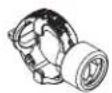
| 6 | 0179 732 | Übergangsstutzen, 1/4" x 3/8" | Connection socket, 1/4" x 3/8" |
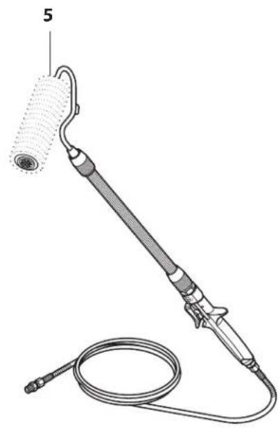
| 7 | 2336 582 | Schlauchpeitsche DN 10 mm, 2,5 m, NPSM 3/8 | Hose whip DN 10 mm, 2.5 m, NPSM 3/8 |
| 8 32 | 03 026 Doppelstutzen 3/8 – 1/2 Double socket 3/8 inch – 1/2 inch | ||
| 9985 783 Doppelstutzen 3/8 – 3/4 Double socket 3/8 inch – 3/4 inch | |||
| 9985 782 Doppelstutzen 1/2 – 3/4 Double socket 1/2 inch – 3/4 inch | |||
| 9 23 | 86 583 Spezial Hochdruckschlauch DN 10 mm, 15 m, NPSM 3/8 | Spezial high-pressure hose DN 10 mm, 15 m, NPSM 3/8 inch | |
| 2336584 | Spezial Hochdruckschlauch DN 10 mm, 30 m, NPSM 3/8 | Special high-pressure hose DN 10 mm, 30 m, NPSM 3/8 inch | |
| 2336 585 Spezial Hochdruckschlauch DN 13 mm, 15 m, NPSM 1/2 | Spezial high-pressure hose DN 13 mm, 15 m, NPSM 1/2 inch | ||
| 2336 586 Spezial-Hochdruckschlauch DN 19 mm, 15 m, NPSM 3/4 | Spezial high-pressure hose DN 19 mm, 15 m, NPSM 3/4 inch | ||
| 10 | 808-550 | Sechskantschraube, 3/8" Anschluss am Hochdruckfilter | Hex fitting, 3/8" (for high-pressure filter) |
| 0349610 | Sechskantschraube, 1/2" Anschluss am Hochdruckfilter | Hex fitting, 1/2" (for high-pressure filter) |
| Pos. | HC 950HC 950-SSPHC 970HC 970-SSP | FDésignation | IDenominazione |
| 1 05 | 02 166 Pistolet AG | 14, TradeTip 2-F Aerografo AG 14, attacco F | |
| 0502 119 Pistolet AG 14, TradeTip 2-G Aerografo AG 14, attacco G | |||
| 2 02 | 89 391 Porte buse | F TradeTip 3 Supporto Tip TradeTip 2, Filettatura F | |
| 0289 390 Porte buse | G TradeTip 3 Supporto Tip TradeTip 2, Filettatura G | ||
| 3 05 | 53 xxx Wagner TradeTip 3 Wagner TradeTip 2 | ||
| 4 02 | 71 065 Porte buse | 2Speed Tip Supporto 2Speed Tip | |
| 5 02 | 71 xxx Wagner 2S speed Tip buse | Wagner 2Speed Tip | |
| 6 01 | 79 732 Raccord 1/4" x 3/8" Bocchettone di transizione 1/4" x 3/8" | ||
| 7 | 2336 582 | Fouet du flexible DN 10 mm, 2,5 m, NPSM 3/8 | Tubo flessibile a sferza DN 10 mm, 2,5 m, NPSM 3/8 |
| 8 32 | 03 026 Raccord double 3/8 – 1/2 | Bocchettone doppio 3/8 – 1/2 | |
| 9985 783 Raccord double 3/8 – 3/4 | Bocchettone doppio 3/8 – 3/4 | ||
| 9985 782 Raccord double 1/2 – 3/4 | Bocchettone doppio 1/2 – 3/4 | ||
| 9 23 | 86 583 Flexible à haute pression spécial DN 10 mm, 15 m, NPSM 3/8 | Tubo flessibile ad alta pressione speciale DN 10 mm, 15 m, NPSM 3/8 | |
| 2336584 | Flexible à haute pression spécial DN 10 mm, 30 m, NPSM 3/8 | Tubo flessibile ad alta pressione speciale DN 10 mm, 30 m, NPSM 3/8 | |
| 2336 585 Flexible à haute pression spécial DN 13 mm, 15 m, NPSM 1/2 | Tubo flessibile ad alta pressione speciale DN 13 mm, 15 m, NPSM 1/2 | ||
| 2336 586 Flexible à haute pression spécial DN 19 mm, 15 m, NPSM 3/4 | Tubo flessibile ad alta pressione speciale DN 19 mm, 15 m, NPSM 3/4 | ||
| 10 | 808-550 | Raccord hexagonal, 0,9 cm (filtre à haute pression) | Alloggiamento esagonale, 3/8" (filtro ad alta pressione) |
| 0349610 | Raccord hexagonal, 1,3 cm (filtre à haute pression) | Alloggiamento esagonale, 1/2" (filtro ad alta pressione) | |
natural_image
Line drawing of a handheld device with a lever and handle (no text or symbols)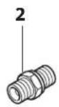
natural_image
Technical line drawing of a medical or laboratory device with a coiled tube and attached rod (no text or symbols)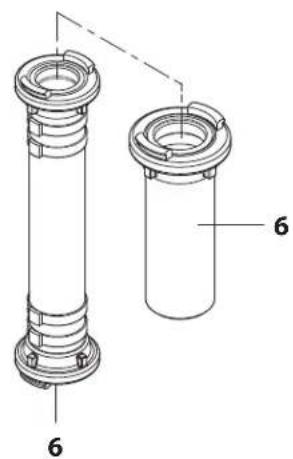
natural_image
Line drawing of a two-wheeled pushrower with wheels and handle (no text or symbols)F Ensemble principal
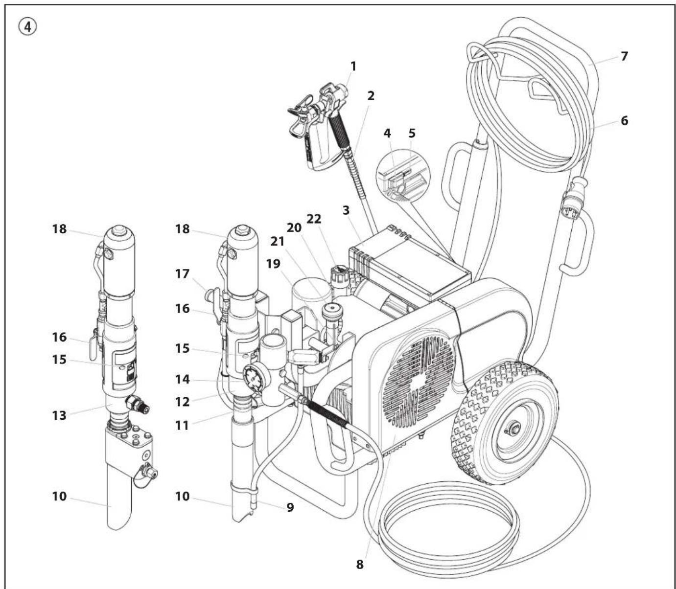
| Pos. HC950 HC950-SSP HC970 HC970-SSP | DBenennung | GBDescription | FDescription | IDenominazione | ||||
| 1* 0528013 0528610 0528017 0528028 Motoren-/ | Pumpenbaugruppe | Motor / pump assembly | Bloc moteur/pompe Gruppo motore/ pompa | |||||
| 2 0556101 0556101 0556101 Drehlageraufbau | (beinhaltet Teile 3) | Swivel fitting assembly (includes item 3) | Raccord articulé (inclut le élément 3) | Gruppo raccordo a snodo (include voci 3) | ||||
| 3 0556072 0556072 0556072 O-ring O-ring Joint torique O-ring | ||||||||
| 4* 0556645 0555645 0555645 Ablassventil Bleed valve Vanne de purge Valvola di sfiato | ||||||||
| 5* | ---- | ---- | ---- | ---- | Filterbaugruppe | Filter assembly | Ensemble de filtre | Gruppo filtro |
| 6 | 0528034 | 0528034 | 0528034 | 0528034 | Entlüftungsschlauch | Bleed hose | Tuyau de purge | Flessibile di sfiato |
| 7 | 0528095 | 0528095 | 0528095 | 0528095 | Schlauchklemme | Hose clamp | Bride de serrage | Fascetta del flessibile |
| 8* | 0528605A | 0528605A | 0528605A | 0528605A | Abdeckung Keilriemen | Belt guard assembly | Protège-courroie Gruppo riparo cinghia | |
| 9 | 9821503 | 9821503 | 9821503 | 9821503 | Federscheibe | Lock washer | Rondelle d'arrêt | Rondella elastica di sicurezza |
| 10 | 9800312 | 9800312 | 9800312 | 9800312 | Schraube | Screw | Vis | Vite |
| 11 | 0528333A | 0528333A | 0528333A | 0528333A | Tankabdeckung | Hydraulic cover | Couvercle | Copertura |
| 12 | 770-879 | 770-879 | 770-879 | 770-879 | Federscheibe (2) | Lock washer (2) | Rondelle d'arrêt (2) | Rondella elastica di sicurezza (2) |
| 13 | 862-501 | 862-501 | 862-501 | 862-501 | Schraube (2) | Screw (2) | Vis (2) | Vite (2) |
| 14* | ---- | ---- | ---- | ---- | Hydrauliksystem | Hydraulic system | Système hydraulique | Sistema idraulico |
| 15 | 0349302 | 0349302 | 0349302 | 0349302 | Klammerschraube (2) | Bracket screw (2) | Vis du support (2) | Vite della staffa (2) |
| 16 | 0509772 | 0509772 | 0509772 | 0509772 | Federscheibe | Lock washer | Rondelle d'arrêt | Rondella elastica di sicurezza |
| 17 | 0528235 | 0528235 | 0528235 | 0528235 | Befestigungswinkel | Bracket | Equerre de fixation | Squadretta di fissagio |
| 18* | 0528611A | 0528611A | ---- | ---- | Convertokit, Elektromotor, 230V | Convertokit, DC electric, 230V | Convertokit, moteur électrique, 230V | Convertokit, DC elettrico (230V) |
| 19* | ---- | ---- | 0528612A | 0528612A | Convertokit, Elektromotor, 400V | Convertokit, DC electric, 400V | Convertokit, moteur électrique, 400V | Convertokit, DC elettrico (400V) |
| 20 449-125 449-125 0290510 0290510 Keilriemen, "V", Convertokit, Benzinmotor | Belt, "V", Convertokit, gas motor | Covroie, "V", moteur essence | Cinghia a "V", Convertokit, benzina | |||||
| 21* | 451-070 | 451-070 | 451-070 | 451-070 | Wagenbaugruppe | Cart assembly | Ensemble de chariot | Gruppo carrello |
| 22 | 0349480 | 0349480 | 0349480 | 0349480 | Schraube (2) | Screw (2) | Vis (2) | Vite (2) |
| 23 | 0349362 | 0349362 | 0349362 | 0349362 | Scheibe (2) | Washer (2) | Rondelle (2) | Rondella (2) |
| 24* | 0290614A | 0290614A | ---- | ---- | Convertokit, 4,8 PS, Honda, Benzin | Convertokit, 4.8 Hp, Honda, gasoline | Convertokit, 4,8 HP, Honda, essence | Convertokit, 4,8 HP, Honda, benzina |
| ---- ---- | 0290456A | 0290456A | Convertokit, 8,5 PS, Honda, Benzin | Convertokit, 8.5 Hp, Honda, gasoline | Convertokit, 8,5 HP, Honda, essence | Convertokit, 8,5 HP, Honda, essence | Convertokit, 8,5 HP, Honda, benzina | |
* Siehe separate Auflistung / See separate listing / voir la liste de pièces distincte / Vedere elenco a parte
| Pos. | HC950 HC950-SSP | HC970 HC970-SSP | D Benennung | GB Description | F Description | I Denominazione |
| 1 0528 | 089 0528089 Deichsel Handle Poignée Manubrio | |||||
| 2 9841 | 504 9841504 Haltefeder (2) Snapbutton (2) Ressort (2) Molla di tenuta (2) | |||||
| 3 0295 | 609 0295609 Scheibe (2) Washer (2) Rondelle (2) Rondella (2) | |||||
| 4 0295 | 610 0295610 Spannhülse (2) Roll pin (2) Goupille de serrage (2) Bussola di serraggio (2) | |||||
| 5 | 0295607 | 0295 607 | Buchse (2) | Sleeve (2) | Douille (2) | Bussola (2) |
| 6 | 0528084 | 0528084 | Wagengriffdistanzelement | Cart handle spacer | Entretoise de la poignée du chariot | Spaziatore impugnatura cart |
| 7 | 0528088 | 0528088 | Sicherungsring (2) | Retaining ring (2) | Bague de retenue (2) | Anello di ritegno (2) |
| 8 0295 | 687 0295687 Scheibe (4) Washer (4) Rondelle (4) Rondella (4) | |||||
| 9 | 0528087 | 0528087 | Schwingenachse | Swing arm axle | Essieu du bras oscillant | Assale braccio oscillante |
| 10 | 0509239 | 0509239 | Kurbelkeil | Cotter pin | Goupille fendue | Coppiglia |
| 11 | 0349324 | 0349324 | Griff | Grip | Poignée | Impugnatura |
| 12 | 0349327 | 0349327 | Sicherungsbolzen | Lock pin | Goupille de verrouillage | Perno di blocco |
| 13 | 0349328 | 0349328 | Feder | Spring | Ressort | Molla |
| 14 | 0528086 | 0528086 | Schwinge | Swing arm | Bras oscillant | Braccio oscillante |
| 15 | 0295606 0295606 Scheibe (4) Washer (4) Rondelle (4) Rondella (4) | |||||
| 16 | 0295608 | 0295608 | Schraube | Screw | Vis | Vite |
| 17 | 0528341A | 0528341A | Grundgestell | Frame, welded | Chàssis | Telaio base del carrello |
| 18 | 0509390 | 0509390 | Rad (2) | Wheel (2) | Roue (2) | Ruota (2) |
| 19 | 0509625 | 0509625 | Radkappe (2) | Wheel cap (2) | Chapeau de roue (2) | Coppa coprimozzo (2) |
| 20 | 0528085 | 0528085 | Stopfen (2) | Plug (2) | Fiche (2) | Tappo (2) |
| Pos. | HC950 HC950-SSP | HC970 HC970-SSP | D Benennung | GB Description | F Description | I Denominazione |
| 1 0349 | 516 0349616 Aufkleber Knob | Aufkleber Knob | decal Etiquette Decalcomania | |||
| 2 0349 | 492 0349492 Sicherungsschraube Set screw Vis de blocage Vite di arresto | |||||
| 3 | 0349341 | 0349341 | Druckregulierknopf | Pressure control knob | Bouton de réglage de pression | Manopola di controllo pressione |
| 4 0555 | 969 0555969 Controller Controller Commandes Comandi | |||||
| 5 | 0349455 | 0349455 | Hydraulikölpumpe | Hydraulic pump | Pompe hydraulique | Pompa idraulica |
| 6 | 0349456 | 0349456 | Passfeder | Key, pump | Clavette | Chiave, pompa |
| 7 0349 | 345 0349345 Sicherungsschraube Set screw Vis de blocage Vite di arresto | |||||
| 8 | 0349225 | 0349225 | Riemenscheibe | Pulley/fan assembly | Poulie | Gruppo puleggia/ventilatore |
| 9 | 0349339 | 0349339 | Rohranschluss | Tube connector | Connecteur de tube | Raccordo tubo |
| 10 | 0349302 | 0349302 | Schraube (8) | Screw (8) | Vis (8) | Vite (8) |
| 11 | 0349303 | 0349303 | Federscheibe (10) | Lock washer (10) | Rondelle d'arrêt (10) | Rondella di sicurezza (10) |
| 12 | 0349360 | 0349360 | O-ring | O-ring | Joint torique | O-ring |
| 13 | 0349356 | 0349356 | Rücklaufschlauch | Return hose assembly | Tuyau de retour | Gruppo tubo di ritorno |
| 14 | 0349465 | 0349465 | Anschluss, 45° | Fitting, 45° | Raccord, 45° | Raccordo, 45° |
| 15 | 0349463 | 0349463 | Adapter | Adapter | Adaptateur | Adattatore |
| 16 | 0290770 | 0290770 | Öltankdeckel | Tank cover | Couvercle du réservoir d'huile | Coperchio serbatoio |
| 17 | 0349350 | 0349350 | Dichtung | Tank gasket | Joint | Guarnizione serbatoio |
| 18 | 0349348 | 0349348 | Senkschraube (2) | Socket screw (2) | Vis à tête fraisée (2) | Vite a brugola (2) |
| 19 | 0349347 | 0349347 | Scheibe (2) | Washer (2) | Rondelle (2) | Rondella (2) |
| 20 | 0349349 | 0349349 | Schraube (2) | Screw (2) | Vis (2) | Vite (2) |
| 21 | 0528171 | 0528171 | Doppelnippel | Nipple | Raccord double | Nipplo |
| 22 | 0349352 | 0349352 | Winkel | Elbow, street | Coude | Gomito, chiusino |
| 23 | 0349353 | 0349353 | Filter | Inlet screen | Filtre | Schermo d'ingresso |
| 24 | 0349375 | 0349375 | Sechskantschraube (2) | Hexagonal bolt (2) | Vis hexagonale (2) | Bullone a testa esagonale (2) |
| 25 | 0254426 | 0254426 | Scheibe (6) | Flat washer (6) | Rondelle (6) | Rondella piatta (6) |
| 26 | 449-718A | 449-718A | Hydrauliköltank | Hydraulic tank | Réservoir d'huile hydraulique | Serbatoio idraulico |
| 27 | 0349458 | 0349458 | Stellmutter (2) | Locknut (2) | Écrou d'arrêt (2) | Dado di sicurezza (2) |
| 28 | 0349484 | 0349484 | Verschlussschraube | Plug | Vis bouchon | Spina |
| 29 | 0509292 | 0509292 | Federscheibe (4) | Lock washer (4) | Rondelle d'arrêt (4) | Rondella di sicurezza (4) |
| 30 | 0349363 | 0349363 | Sechskantschraube | Hexagonal bolt | Vis hexagonale | Bullone a testa esagonale |
| 31 | 0509421 | 0509421 | Sechskantschraube | Hexagonal bolt | Vis hexagonale | Bullone a testa esagonale |
| 32 | 0349340 | 0349340 | Winkel | Elbow | Coude | Gomito |
| 33 | 0349338 | 0349338 | Schlauchklemme | Hose clamp | Collier | Fascetta per tubi |
| 34 | 0349337 | 0349337 | Rohr | Tubing, PTFE | Tube | Tubatura, PTFE |
| 35 | 0349358 | 0349358 | Druckschlauch | Pressure hose assembly | Tuyau de pression | Gruppo tubo della pressione |
| 36 | 0349487 | 0349487 | Winkel | Elbow | Coude | Gomito |
| 37 | 0555469 | 0555469 | Filter | Hydraulic filter | Filtre | Filtro idraulico |
| 38 | 0349361 | 0349361 | Erdungsschiene | Ground lug | Barrette de mise à la masse | Tenone terra |
| 39 | 0349614 | 0349614 | Ölmessstab | Hydraulic fluid dipstick | Jauge de niveau | Coperchio/asta livello del fluido idraulico |
| 40 | 0349373 | 0349373 | Bypassventil | Hydraulic by-pass | By-pass | By-pass idraulico |
| 41 | 0349467 | 0349467 | Einfüllstutzen | Tube assembly | Raccord de remplissage | Gruppo tubo |
| 42 | 0528164A | 0528164A | Rohr | Tube | Tube | Tubatura |
| 43 | 0349368 | 0349368 | Flügelschraube | Thumb screw | Vis à ailes | Vite a testa zigrinata |
| 44 | 0349369 | 0349369 | Hutmutter | Acorn nut | Ecrou borgne | Dado ad alette |
| 45 | 0509285 | 0509285 | Scheibe | Washer | Rondelle | Rondella piatta |
| 46 | 0349370 | 0349370 | Riegel | Mounting plate retainer | Verrou | Fermo piastra di montaggio |
| 47 | 0349371 | 0349371 | Distanzscheibe | Spacer | Bague d'espacement | Distanziatore |
| Pos. | HC950 HC950-SSP | HC970 HC970-SSP | D Benennung | GB Description | F Description | I Denominazione |
| 1 | 0349384 | 0349384 | Zylinderkopfstöpsel | Cylinder head plug | Fiche de la tête du cylindre | Tappo testata cilindro |
| 2 0349 | 385 0349385 O-ring | O-ring Joint torique O-ring | ||||
| 3 | 0349386 | 0349386 | Flexible Stellmutter | Flex lock nut | Écrou de blocage souple | Dado di bloccaggio cordone |
| 4 0349 | 378 0349378 Bedienungsarretierung (2) Trip retainer (2) Dispositif de retenue du déclenchement (2) | Fermo scatto (2) | ||||
| 5 0349 | 379 0349379 O-ring (2) O-ring (2) Joint torique (2) O-ring (2) | |||||
| 6 | 0349380 | 0349380 | Bedienungsfeder (2) | Trip spring (2) | Ressort de déclenchement (2) | Molla scatto (2) |
| 7 | 0349381 | 0349381 | Kugel, SS (2) | Ball, SS (2) | Bille, SS | Sfera, SS (2) |
| 8 | 0349388 | 0349388 | Zylinderkopf | Cylinder head | Tête du cylindre | Testata cilindro |
| 9 0349 | 389 0349389 O-ring (2) O-ring (2) Joint torique (2) O-ring (2) | |||||
| 10 | 0349382 | 0349382 | Spule / Abziehhülsensatz | Spool / sleeve set | Ensemble tiroir/manchon | Set bobina / manicotto |
| 11 | 0349383 | 0349383 | O-ring (3) | O-ring (3) | Joint torique (3) | O-ring (3) |
| 12 | 0349390 0349390 | Distanzring | Sleeve retainer | Dispositif de retenue du manchon | Fermo manicotto | |
| 13 | 0349391 | 0349391 | Haltering | Retainer ring | Bague de retenue | Anello di fermo |
| 14 | 0349393 | 0349393 | Kolbenarretierschraube | Piston retainer screw | Vis de retenue du piston | Vite fermo pistone |
| 15 | 0349394 | 0349394 | Kolben | Piston | Piston | Pistone |
| 16 | 0349395 | 0349395 | Kolbendichtung | Piston seal | Joint du piston | Guarnizione pistone |
| 17 | 0349396 0349396 O-ring O-ring Joint torique O-ring | |||||
| 18 | 0349397 0349627 | Ventilstangenbaugruppe | Valve rod assembly | Tige de soupape | Gruppo stelo valvola | |
| 19 | 0349398 | 0349633 | Kolbenstange | Piston rod | Tige du piston | Stelo pistone |
| 20 | 0349516 | 0349516 | Winkel, 90° | Elbow, 90° | Coude, 90° | Gomito, 90° |
| 21 | 0555480 | 0555480 | O-ring (2) | O-ring (2) | Joint torique (2) | O-ring (2) |
| 22 | 192-051 | 192-051 | Elbow (includes item 21) | Winkel (beinhaltet Teile 21) | Coude (inclut le élément 21) | Gomito (include voci 21) |
| 23 | 0537563 | 0537531 | Motorenrohr | Motor tube | Tube moteur | Tubo motore |
| 24 | 0537564 | 0537564 | Tee (includes item 21) | T-Stück (beinhaltet Teile 21) | Raccord en T (inclut le élément 21) | Derivazione a T (include voci 21) |
| 25 | 431-019 | 431-019 | Fitting | Anschluss | Raccord | Alloggiamento |
| 26 | 0349399 | 0349399 | Seegerring | Lock ring | Bague de retenue | Anello di bloccaggio |
| 27 | 0349626 | 0349400 | Zylinder | Cylinder | Cylindre | Cilindro |
| 28 | 0349401 | 0349401 | Stangendichtung | Rod seal | Joint de tige | Guarnizione asta |
| 29 | 0555647 | 0555680 | Motor/Pumpenblock | Motor/pump block | Bloc moteur/pompe | Blocco motore/pompa |
| 30 | 0509418 | 0509418 | Kugelhahn | Ball valve | Vanne à bille | Valvola a sfera |
| 31 | 0528096 | 0528096 | Drehlageraufbau | Swivel fitting assembly | Raccord articulé | Gruppo raccordo a snodo |
| 0349703 0349703 Motorenservicesatz — klein (beinhaltet Teile 2-3, 5-7, 9, 11, 16, 17, und 28) | Motor service kit, minor (includes items 2, 3, 5-7, 9, 11, 16, 17, and 28) | Kit d'entretien du moteur – mineur (inclut les éléments 2 à 3, 5 à 7, 9, 11, 16 à 17, et 28) | Kit servizio motore — minimo (include voci 2, 3, 5-7, 9, 11, 16, 17, e 28) | |||
| 0537926 0537928 Motor tube kit (includes items 21-25) | Motorrohr-Kit (beinhaltet Teile 21-25) | Kit tube à moteur (inclut les éléments 21 à 25) | Kit tubo motore (comprende articoli 21-25) | |||
| Pos. HC950 | HC950-SSP HC970 | HC970-SSP | DBenennung | GBDescription | FDescription | IDenominazione | ||
| 1 0349406 0349406 0349406 0349406 0349406 0349406 0349406 0349406 0349406 0349406 0349406 0349406 0349406 03 | ||||||||
| 2 | 0349407 | 0349407 | 0349407 | 0349407 | Verbindungsstift | Connecting pin | Goupille de liaison | Pino de ligação |
| 3 0349473 0349473 0349473 0349473 0349473 0349473 0349473 0349473 0349473 0349473 0349473 0349473 0349473 0 | 0349473 0349473 0349473 0349473 0349473 0349473 0349473 0349473 0349473 0349473 0349473 0349473 034 | 0349473 0349473 0349473 0349473 0349473 0349473 0349473 0349473 0349473 0349473 0349473 0349473 03 | 0349473 Abdeckung (2) Cover (2) Couvercle (2) Copertura (2) | |||||
| 4 0349472 03494972 03494972 03494972 Schraube (2) Screw (2) Vis (2) Vite (2) | ||||||||
| 5 | 0349408 | 0349408 | 0349408 | 0349408 | O-ring, PTFE (2) | O-ring, PTFE (2) | Joint torique, PTFE (3) | Anel em O, PTFE (2) |
| 6 0349409 03494909 03494909 03494909 03494909 03494909 03494909 03494909 03494909 03494909 03494909 03494909 03494910 Konusfeder (2) Upper packing spring | 0349408 | 0349408 | 0349408 | 0349408 | Leder/Ultrahochmolekular-gewichtigesPolyethylen/Stahl (2) | Packing set, leather/UHMWPE/steel (2) | Garniture, cuir/UHMWPE/acier (2) | Conjunto de empanque, couro/UHMWPE/aço (2) |
| 7 0349410 0349410 0349410 0349410 Konusfeder (2) Upper packing spring | 0349410 0349410 0349410 0349410 0349410 0349410 0349410 0349410 0349410 0349410 0349410 0349410 0349410 034 | 0349410 0349410 Konusfeder (2) Upper packing spring | 0349410 Konusfeder (2) Upper packing spring | (2) | Ressort de garniture supérieure (2) | Mola do empanque superior (2) | ||
| 8 | 0349596 | 0550036 | 0349411 | 0550037 | Kolbenstange | Displacement rod | Tige de piston | Haste de deslocamento |
| 9 | 0349412 | 0349412 | 0349412 | 0349412 | Federhalter | Spring retainer | Ressort conique | Retentor de mola |
| 10 | 0349413 | 0349413 | 0349413 | 0349413 | Druckfeder | Lower packing spring | Ressort de garniture inférieure | Mola do empanque inferior |
| 11 | 0349622 | ---- | 0349622 | ---- | Ablassventilkorb | Outlet valve cage | Cage de soupape de sortie | Gaiola da válvula de escape |
| 12 | 0509710 | 9941501 | 0509710 | 9941501 | Kugel | Outlet valve ball | Bille | Esfera da válvula de escape |
| 13 | 0555668 | ---- | 0555668 | ---- | Auslassventilsitz | Outlet valve seat | Siège du clapet de refoulement | Sede da válvula de escape |
| 14 | 0555669 | ---- | 0555669 | ---- | Scheibe | Seal washer | Rondelle | Arruela de vedação |
| 15* | 0555670 | ---- | 0555670 | ---- | Auslassventilgehäuse | Outlet valve housing | Corps du clapet de refoulement | Corpo da válvula de escape |
| 16 | 0349606 | 0349606 | 0349416 | 0349416 | Zylinder | Pump cylinder | Cylindre | Cilindro da bomba |
| 17 | 0349417 | 0349417 | 0349417 | 0349417 | O-ring | O-ring | Joint torique | Anel em O |
| 18 | 0528081 | 0528081 | 0528081 | 0528081 | Scheibe | Wave washer | Rondelle | Arruela |
| 19 | 0555672 | ---- | 0555672 | ---- | Kugelführung | Foot valve cage | Guide de bille | Gaiola da válvula de pé |
| 20 | 0509707 | ---- | 0509707 | ---- | Kugel | Foot valve ball | Bille | Esfera da válvula de pé |
| 21 | 0509623 | ---- | 0509623 | ---- | Einlassventilsitz | Foot valve seat | Siège | Sede da válvula de pé |
| 22 | 0509708 | ---- | 0509708 | ---- | Sitz o-ring | Seat o-ring | Siège du joint torique | Anel em O da sede |
| 23 | 0528011 | ---- | 0528011 | ---- | Einlassventilgehäuse | Foot valve housing | Logement du clapet de pied | Corpo da válvula de pé |
| 24 | 0349300 | ---- | 0349300 | ---- | Ansaugrohr | Siphon tube | Tube d'aspiration | Tubo de aspirazione |
| HC950 | HC950-SSP HC970 | HC970-SSP | ||||||
| 0528102 0537901 0528103 0537900 Flüssigkeitsbereich Wartungssatz, gross (beinhaltet Teile 8, 16 und Flüssigkeitsbereich Wartungssatz, klein P/N 0528101) | Fluid section service kit, major (includes items 8, 16, and fluid section service kit, minor P/N 0528101) | Kit de maintenance de la section des liquides, principal (inclut les éléments 8, 16, et le kit de maintenance de la section des fluides, mineur, n° de pièce 0528101) | Kit servizio sezione fluido, massimo (include voci 8, 16, ed il kit servizio sezione fluido, minimo P/N 0528101) | |||||
| 0528101 | ---- | 0528101 | ---- | Flüssigkeitsbereich Wartungssatz, klein (beinhaltet Teile 1, 5, 6, 11, 12, 14, 17, 20, 22, und Loctite P/N 426-051) | Fluid section service kit, minor (includes items 1, 5, 6, 11, 12, 14, 17, 20, 22, and Loctite P/N 426-051) | Kit de maintenance de la section des liquides, mineur (inclut les éléments 1, 5, 6, 11, 12, 14, 17, 20, 22 et Loctite n° de pièce 426-051) | Kit servizio sezione fluido, minimo (include voci 1, 5, 6, 11, 12, 14, 17, 20, 22 e Loctite P/N 426-051) | |
| ---- | 0528705 | ---- | 0528705 | Flüssigkeitsbereich Wartungssatz, klein (beinhaltet Teile 1, 5, 6, 12, 17, und Loctite P/N 426-051) | Fluid section service kit, minor (includes items 1, 5, 6, 12, 17, and Loctite P/N 426-051) | Kit de maintenance de la section des liquides, mineur (inclut les éléments 1, 5, 6, 12, 17, et Loctite n° de pièce 426-051) | Kit servizio sezione fluido, minimo (include voci 1, 5, 6, 12, 17, e Loctite P/N 426-051) | |
| 0555678 | ---- | 0555678 | ---- | Ablassventilbaugruppe (beinhaltet Teile 11-15) | Outlet valve assembly (includes items 11-15) | Soupape de sortie (inclut les éléments 11-15) | Gruppo valvola d'uscita (include voci 11-15) | |
| Pos. HC950-SSP HC970-SSP | DBenennung | GBDescription | FDescription | IDenominazione | ||
| 1 9907 | 195 9907 195 Sechskantschraube | (4) Hex screw (4) Vis (4) Vite (4) | ||||
| 2 9920 | 102 9920 102 Scheibe (4) Washer | (4) Rondelle (4) Rondella (4) | ||||
| 3 9900 | 513 9900 513 Schraube Screw Vis | Vite | ||||
| 4 0349 | 683 0349 683 Druckplatte Pressure plate Plat de pression Disco di pressione | |||||
| 5 | 0349 684 | 0349 684 | Verschlussplatte | Plug plate | Plat de bouchon | Tappo |
| 6 | 0367 525 | 0367 525 | O-ring (2) | O-ring (2) | Joint torique (2) | O-ring (2) |
| 7 | 0349 685 | 0349 685 | Dichtring | Sealing ring | Bague d'étoupage | Guarnizione |
| 8 | 0349 556 | 0349 556 | Kugelführung | Ball cage | Guide de bille | Guida della sfera |
| 9 | 0037 776 | 0037 776 | Druckfeder | Pressure spring | Ressort de pression | Molla a pressione |
| 10 | 9941 537 | 9941 537 | Kugel | Ball | Bille | Sfera |
| 11 | 0349 557 | 0349 557 | Kugelsitz | Ball seat | Siège de bille | Sede della sfera |
| 12 | 9930 411 | 9930 411 | Halbrundkerbnagel | Grooved pin | Goupille cannelée | Perno |
| 13 | 9906 025 | 9906 025 | Zylinderschraube | Head cap screw | Vis de chapeau | Vite |
| 14 | 2337 803 | 2337 803 | O-ring | O-ring | Joint torique | O-ring |
| 15 | 0349 555 | 0349 555 | Verschluss | Plug | Bouchon | Tappo |
| 16 | 0349 152 | 0349 152 | Verschlussschraube | Plug assembly | Bouchon complète | Gruppo tappo |
| 17 | 0349 688 0349 688 Verschlussschraube mit Stutzen | Sealing plug with adapter | Bouchon avec l'adapteur | Tappo con l'adattatore | ||
| 18 | 9971 148 | 9971 148 | O-ring | O-ring | Joint torique | O-ring |
| 19 | 9941 501 | 9941 501 | Kugel | Ball | Bille | Sfera |
| 20* | 0349 151 | 0349 151 | Auslassventilsitz kpl. | Outlet valve assembly | Clapet de refoulement | Gruppo della valvola di scarico |
| 21 | 9910 712 | 9910 712 | Hutmutter M 6 (2) | Cap nut M 6 (2) | Ecrou borgne M 6 (2) | Dado cieco M 6 (2) |
| 22 | 9923 501 | 9923 501 | Tellerfeder (4) | Disk spring (4) | Ressort plat (4) | Molla a tazza (4) |
| 23 | 0349 690 | 0349 690 | Anschlusselement | Connection element | Segment de raccordement | Elemento di raccordo |
| 24 | 9910 113 | 9910 113 | Sechskantmutter M 6 | Hexagon nut M 6 | Ecrou hexagonal M 6 | Dado esagonale M 6 |
| 25 | 0349 551 | 0349 551 | Lochschraube | Flat perforated screw | Vis perforée | Vite forata |
| 26 | 9923 504 | 9923 504 | Tellerfeder | Disk spring | Ressort plat | Molla a tazza |
| 27 | 0349 576 | 0349 576 | Packungssatz | Packing, complete | Garniture complète | Guarnizione completa |
| 28 | 3053 865 | 3053 865 | Sicherungsring | Retaining ring | Bague de retenue | Anello di ritegno |
| 29 | 0349687 | 0349687 | Ensatz | Insert | Douille | Manicotto |
| 30 | 9971 353 | 9971 353 | O-ring 21 x 2 | O-ring 21 x 2 | Joint torique 21 x 2 | O-ring 21 x 2 |
| 31 | 0349 408 | 0349 408 | O-ring 50 x 1.78 | O-ring 50 x 1.78 | Joint torique 50 x 1.78 | O-ring 50 x 1.78 |
| 32 | 0349 686 | 0349 686 | Nutmutter | Groove nut | Ecrou | Dado |
| 33 | 0349 682 | 0349 682 | Einlassventilgehäuse | Inlet valve housing | Corps de la soupape d'aspiration | Alloggiamento della valvola di entrata |
| 34 | 9971 489 | 9971 489 | O-ring 47 x 2.5 | O-ring 47 x 2.5 | Joint torique 47 x 2.5 | O-ring 47 x 2.5 |
| 35 | 0349 545 | 0349 545 | Stange | Rod | Tige | Barra |
| 36 | 9920 311 | 9920 311 | Scheibe | Washer | Rondelle (2) | Rondella |
| 37 | 0349 544 | 0349 544 | Schöpfkolbenplatte | Shovel valve plate | Plateau du piston à auget | Disco della valvola di mandata |
| 38 | 0349 543 | 0349 543 | Schöpfkolben | Shovel valve | Piston à auget | Valvola di mandata |
| 39 | 0349 580 | 0349 580 | Ansaugrohr | Suction tube | Tube d'aspiration | Tubo di aspirazione |
| 0349 150 | 0349 150 | Schöpfkolben kpl. | Shovel valve assembly | Piston à auget complète | Gruppo della valvola di mandata | |
GB High-pressure filter
| Pos. HC950 | HC950-SSP HC970 | HC970-SSP | DBenennung | GBDescription | FDescription | IDenominazione | ||
| 1 | 0290443 | 0290443 | 0290443 | 0290443 | Gehäusedeckel | Filter cap assembly | Couvercle du corps | Coperchio dell'alloggiamento |
| 2 0349 | 430 0349430 | 0349430 03 | 49430 Druckfeder Spring | feder Spring | Ressort Molla | |||
| 3 0349 | 707 0349707 | 0349707 03 | 49707 Filterpatrone, 0 | Maschen, mit Kugel | Filter element, 0 M, with ball | Cartouche de filtre 0 mailles, avec bille | Elemento filtro, 0 M, con sfera | |
| 0349704* | 0349704* 03 | 49704* 0349 | 704* Filterpatrone, 50 Maschen, mit Kugel | Matron, mit Kugel | Filter element, 50 M, with ball | Cartouche de filtre 50 mailles, avec bille | Elemento filtro, 50 M, con sfera | |
| 0349431* | 0349431* 03 | 49431* 0349 | 431* Filterpatrone, 5 Maschen, mit Kugel | Matron, mit Kugel | Filter element, 5 M, with ball | Cartouche de filtre 5 mailles, avec bille | Elemento filtro, 5 M, con sfera | |
| 0349705* | 0349705* 03 | 49705* 0349 | 705* Filterpatrone, 100 Maschen, mit Kugel | Matron, mit Kugel | Filter element, 100 M, with ball | Cartouche de filtre 100 mailles, avec bille | Elemento filtro, 100 M, con sfera | |
| 4 0349 | 432 0349432 | 0349432 03 | 49432 Dichtung dick Gasket, PTFE (thick) Joint épais | Guarnizione, PTFE (spesso) | ||||
| 5 0349 | 433 0349433 | 0349433 03 | 49433 Dichtung dünn Gasket, PTFE (thin) Joint mince | Guarnizione, PTFE (sottile) | ||||
| 6 0349 | 434 0349434 | 0349434 03 | 49434 O-Ring O-ring, PTFE Joint torique, PTFE O-ring, PTFE Joint torique, PTFE O-ring, PTFE Joint torique, PTFE O-ring, PTFE Joint torique, PTFE O-ring, PTFE Joint torique, PTFE O-ring, PTFE Joint torique, PTFE O-ring, PTFE Joint torique, PTFE O-ring, PTFE Joint torique, PTFE O-ring, PTFE Joint torque, PTFE O-ring, PTFE Joint torque, PTFE O-ring, PTFE Joint torque, PTFE O-ring, PTFE Joint torque, PTFE O-ring, PTFE Joint torque, PTFE O-ring, PTFE Joint torque, PTFE O-ring, PTFE Joint torque, PTFE O-ring, PTFE Joint torque, PTFE O-ring, PPFGE Joint torque, PTFE O-ring, PTFE Joint torque, PTFE O-ring, PTFE Joint torque, PTFE O-ring, PTFE Joint torque, PTFE O-ring, PTFE Joint torque, PTFE O-ring, PTFE Joint torque, PTFE O-ring, PTFE Joint torque, PTFE O-ring, PTFE Joint torque, PTFE O-ring, PTFE Joint torque, PTFE O-ring, PTFE Joint torque, PTFE O-ring, PTFE Joint torque, PTFE O-ring, PTFE Joint torque, PTFE O-ring, PTFE Joint torque, PTFE O-ring, PTFE Joint torque, PTFE O-ring, PTFE Joint torque, PTFE O-ring, PTFE Joint torque, | Sede, carburo di tungsteno | ||||
| 7 | 0349435 | 0349435 | 0349435 | 0349435 | Ventilsitz | Seat, tungsten carbide | Siège de soupape | Sede, carburo di tungsteno |
| 8 | 0528161 | 0528161 | 0528161 | 0528161 | Manometer | Pressure gauge | Manomètre | Manometro |
| 9 | 0290424 | 0290424 | 0290424 | 0290424 | Gehäuse | Filter body | Corps | Corpo filtro |
| 10 | 0349438 | 0349438 | 0349438 | 0349438 | Verschlussschraube | Pipe plug | Vis bouchon | Tappo tubo |
| 11 | 0509738 | ---- | ---- | ---- | Anschlussgewinde Materialausgang, 3/8" | Fluid outlet fitting, 3/8" | Raccord de la sortie du fluide, 3/8" (0,9 cm) | Raccordo dell'uscita del fluido, 3/8" |
| ---- | 0349610 03 | 349610 0349 | 610 Anschlussgewinde Materialausgang, 1/2" | Fluid outlet fitting, 1/2" | Fluid outlet fitting, 1/2" | Raccord de la sortie du fluide, 1/2" (1,3 cm) | Raccordo dell'uscita del fluido, 1/2" | |
| 12 | 0528082 | 0528082 | 0528082 | 0528082 | Winkelstück, 90° | Elbow, 90° | Coude, 90° | Gomito, 90° |
| 13** | 0555645 | 0555645 | 0555645 | 0555645 | Ablassventil | Bleed valve | Vanne de purge | Valvola di sfiato |
| 0528608A | ---- | ---- | ---- | Filterbaugruppe, 3/8" Anschlussgewinde Materialausgang (beinhaltet Teile 1-13) | Filter assembly, 3/8" fluid outlet fitting (includes items 1-13) | Ensemble de filtre, 0,9 cm raccord de la sortie du fluide, (inclut les éléments 1-13) | Gruppo filtro, 3/8" raccordo dell'uscita del fluido (include voci 1-13) | |
| ---- | 0528609A | 0528609A 05 | 28609A | Filterbaugruppe, 1/2" Anschlussgewinde Materialausgang (beinhaltet Teile 1-13) | Filter assembly, 1/2" fluid outlet fitting (includes items 1-13) | Ensemble de filtre, 1,3 cm raccord de la sortie du fluide, (inclut les éléments 1-13) | Gruppo filtro, 1/2" raccordo dell'uscita del fluido (include voci 1-13) | |
| 0349700 03 | 349700 0349 | 700 0349700 | Filterwartungssatz (beinhaltet Teile 2 und 4-6) | Filter service kit (includes items 2 and 4-6) | Kit d'entretien du filtre (inclut les éléments 2 et 4-6) | Kit servizio filtro (include voci 2 e 4-6) | ||
* Optional / Optional / Facultatif / Opzionale
** Siehe separate Auflistung / See separate listing / voir la liste de pièces distincte / Vedere elenco a parte
| Pos. | HC 950HC 950-SSP | HC 970HC 970-SSP | DBenennung | GBDescription | FDescription | IDenominazione |
| 1 980 | 5427 9805426 | Schraube (2) Screw (2) Vis (2) Vite (2) | ||||
| 2 034 | 9334 0509285 | Scheibe (12) Flat washer (12) Rondelle (12) Rondella (12) | ||||
| 3 232 | 9129 ---- Elektromotor, 3 PS | 50 Hz, 230V | Motor, DC-Electric, 3 Hp, 50 Hz, 230V | Motor électrique, 3 Hp, 50 Hz, 230V | Motore elettrico, 3 Hp, 50 Hz, 230V | |
| ---- 233 | 219 Elektromotor 400 V, 50 Hz, V3~ | Electric motor 400 V, 50 Hz, V3~ | Motor électrique 400 V, 50 Hz, V3~ | Motore elettrico 400 V, 50 Hz, V3~ | ||
| 4 034 | 9643 0349535 | Seilrolle Pulley Poulie Puleggia | ||||
| 5 | 0349537 | 0349537 | Montageplatte | Mounting plate | Plaque de fixation | Piastra di montaggio |
| 6 | 0507786 | ---- | Federscheibe (4) | Lock washer (4) | Rondelle d'arrêt (4) | Rondella di sicurezza (4) |
| ---- | 0509292 | Federscheibe (4) | Lock washer (4) | Rondelle d'arrêt (4) | Rondella di sicurezza (4) | |
| 7 | 0509885 | ---- | Mutter (2) | Nut (2) | Écrou (2) | Dado (2) |
| ---- | 9812320 | Mutter (2) | Nut (2) | Écrou (2) | Dado (2) | |
| 8 | 0290538 | 0290538 | Schaumband (2) | Foam strip (2) | Languette en mousse (2) | Striscia in schiuma (2) |
| 9 | 0528339A | 0528339A | Schild | Shield | Écran protecteur | Protezione |
| 10 | 0349333 | 0509293 | Stellmutter (4) | Stop nut (4) | Écrou d'arrêt (4) | Dado di bloccaggio (4) |
| 11 980 | 05444 0509294 | Schraube (2) Screw (2) Vis (2) Vite (2) | ||||
| 12 | 590-411 | 590-411 | Abstandhalter (4) | Spacer (4) | Entretoise (4) | Distanziatore (4) |
| 13 | ---- | 9822632 | Scheibe (4) | Washer (4) | Rondelle (4) | Rondella (4) |
| 14 | 254334 | 254334 | Kondensatorgehäuse | Housing | Carter | Carcassa |
| 15 995 | 52870 ---- Kondensator 60 MF/400-450 V (230 V~, 50 Hz) | Capacitor 60 MF/400-450 V (230 V~, 50 Hz) | Condensateur 60 MF/400-450 V (230 V~, 50 Hz) | Condensatore 60 MF/400-450 V (230 V~, 50 Hz) | ||
| 16 995 | 53704 ---- EIN/AUS-Schalter 230 V~, 50 Hz | ON/OFF switch 230 V~, 50 Hz | Interrupteur MARCHE/ARRET 230 V~, 50 Hz | Interrutore ON/OFF 230 V~, 50 Hz | ||
| ---- 9953704 EIN/AUS-Schalter 400 V, 50 Hz, V3~ | ON/OFF switch 400 V, 50 Hz, V3~ | Interrupteur MARCHE/ARRET 400 V, 50 Hz, V3~ | Interrutore ON/OFF 400 V, 50 Hz, V3~ | |||
| 17 | 2301766 | 2301766 | Kontrollleucht | Control lamp | Lampe de contrôle | Lampada spia |
| 18 995 | 51652 ---- Geräteanschlussleitung H07RN-F3G2,5 - 6m | Power cord H07RN-F3G2.5 - 6m | Cordon d'alimentation H07RN-F3G2,5 - 6m | Cavo di alimentazione elettrica H07RN-F3G2,5 - 6m | ||
| ---- 0349259 Geräteanschlussleitung H07RN-F5G2,5 - 6 m | Power cord H07RN-F5G2.5 - 6 m | Cordon d'alimentation H07RN-F5G2,5 - 6 m | Cavo di alimentazione elettrica H07RN-F5G2,5 - 6 m | |||
| 19 | 9931039 | ---- | Passfeder 8 x 7 x 25 | Featherkey 8 x 7 x 25 | Clavette 8 x 7 x 25 | Linguetta 8 x 7 x 25 |
| ---- | 9931042 | Passfeder 8 x 7 x 45 | Featherkey 8 x 7 x 45 | Clavette 8 x 7 x 45 | Linguetta 8 x 7 x 45 | |
| 20 | 0349644 | 0349644 | Spannbuchse | Spring collet | Douille de serrage | Bussola di serraggio |
| 21 230 | 04608 2304608 | Dichtung Gasket Joint | Guarnizione | |||
| 22 | 9902234 | 9902234 | Schraube | Screw | Vis | Vite |
| 23 | 9950244 | 2306244 | Klemmleiste | Terminal block | Bornes | Morsettiera |
| 24 990 | 00249 9900249 | Schraube (4) Screw (4) Vis (4) Vite (4) | ||||
| 25 | 9902209 | 9902209 | Schraube | Screw | Vis | Vite |
| 26 | 254335 | 254335 | Klemmkasten | Electrical box | Boîte électrique | Scatola elettrica |
| 27 990 | 00518 9900518 | Schraube (4) Screw (4) Vis (4) Vite (4) | ||||
| 28 | 254337 | 254337 | Montageplatte | Mounting plate | Plaque de fixation | Piastra di montaggio |
| 29 | 254336 | 254336 | Dichtung | Gasket | Joint | Guarnizione |
| 30 | 3158661 | 9952685 | Kabelverschraubung | Strain relief | Bride de cordon | Presa cavo |
| 31 052 | 28344 0349538 | Keilriemen, "V", Convertokit, Elektromotor | Belt, "V", Convertokit, DC electric | Courroie, "V", moteur électrique | Cinghia a "V", Convertokit, DC elettrico | |
| 2329130 ---- Elektromotor, 3 PS, 50 Hz, 230V (beinhaltet Teile 3, 14-18 und 21-31) | Motor assembly, 230V complete (includes items 3, 14-18, and 21-31) | Motor électrique, 3 Hp, 50 Hz, 230V (inclut les éléments 3, 14 à 18 et 21 à 31) | Motore elettrico, 3 Hp, 50 Hz, 230V (include voci 3, 14-18, e 21-31) | |||
| Pos. | HC 950 HC 950-SSP | HC 970 HC 970-SSP | D Benennung | GB Description | F Description | I Denominazione |
| 1 860 | -552 0509294 | Schraube (4) | Screw (4) Vis (4) Vite (4) | |||
| 2 034 | 9334 0509285 | Scheibe (8) | Washer (8) Rondelle (8) Rondella (8) | |||
| 3 | 0349589 | ---- | Benzinmotor, 4,8 PS, Honda | Engine, gas, 4.8 Hp, Honda | Moteur, essence 4,8 Honda | Motore, benzina 4,8 HP, Honda |
| ---- | 0349421 | Benzinmotor, 8,5 PS, Honda | Engine, gas, 8.5 Hp, Honda | Moteur, essence 8,5 Honda | Motore, benzina 8,5 HP, Honda | |
| 4 | 0555553 | 0555553 | Passfeder | Key | Clavette | Chiave |
| 5 | 449-984 | 0290409 | Seilrolle | Pulley | Poulie | Puleggia |
| 6 | 0290132 | 0290480 | Montageplatte | Mounting plate | Plaque de fixation | Piastra di montaggio |
| 7 | 0528205 | 0509293 | Stellmutter (4) | Stop nut (4) | Écrou d'arrêt (4) | Dado di bloccaggio (4) |
GB Belt Guard Assembly
| Pos. | HC950 HC950-SSP | HC970 HC970-SSP | D Benennung | GB Description | F Description | I Denominazione |
| 1 | 0528340A | 0528340A | Riemenschutz, hinten | Belt guard, rear | Protège-courroie, derrière | Protezione cinghia, posteriore |
| 2 9805415 | 9805415 Scraube (4) Screw (4) | Vis (4) Vite (4) | ||||
| 3 | 0528329A | 0528329A | Befestigungswinkel | Bracket | Equerre de fixation | Carter inferiore |
| 4 | 9805413 | 9805413 | Schraube | Screw | Vis | Vite |
| 5 | 9822523 | 9822523 | Sicherungsring | Retaining ring | Bague de retenue | Anello di ritegno |
| 6 | 0349347 | 0349347 | Scheibe | Washer | Rondelle | Rondella |
| 7 | 0528345 | 0528345 | Knopf | Bolt | Bouton | Manopola |
| 8 | 0290794 | 0290794 | Gelenkstück | Hinge | Charnière | Cerniera |
| 9 | 0524318 | 0524318 | Mutter | Nut | Écrou | Dado |
| 10 | 0528326A | 0528326A | Riemenschutz, vorne | Belt guard, front | Protège-courroie, devant | Protezione cinghia, anteriore |
| 11 | 0528802 | 0528804 | Aufkleber | Label | Etiquette | Decalcomania |
| Pos. | HC950 HC950-SSP | HC970 HC970-SSP | D Benennung | GB Description | F Description | I Denominazione |
| 1 0555 | 664 0555664 Sechskantschraube | Hex screw Vis hexagonale Vite a testa esagonale | ||||
| 2 0555 | 663 0555663 Schiebe Flat washer | Rondelle Rondella piatta | ||||
| 3 0295 | 731 0295731 Abstandhalter Spacer | Entretoise Distanziatore | ||||
| 4 0295 | 730 0295730 Ventilgriff Valve handle | Poignée de la soupape Maniglia valvola | ||||
| 5 | 9820905 | 9820905 | Federscheibe (3) | Spring washer (3) | Rondelle de ressort (3) | Rondella elastica (3) |
| 6 | 9822516 | 9822516 | Haltering | Retaining ring | Bague de retenue | Anello di tenuta |
| 7 | 0294501 | 0294501 | Ventilunterlagsscheibe | Valve washer | Rondelle de soupape | Rondella valvola |
| 8 | 0555622 | 0555622 | Ventilschaltspindel | Valve stem | Tige de soupape | Steli della valvola |
| 9 | 9871045 | 9871045 | Schaltspindel O-Ring | Stem O-ring | Joint torique de la tige | Stelo dell' o-ring |
| 10 | 0555767 | 0555767 | Ventilgehäuse | Valve housing | Logement de la soupape | Corpo valvola |
| 11 | 9841502 | 9841502 | Kugel | Ball | Bille | Sfera |
| 12 | 0555766 | 0555766 | Ventilsitz | Valve seat | Siège de la soupape | Sede valvola |
| 13 | 0294499 | 0294499 | Ventildichtung | Valve seal | Joint de la soupape | Guarnizione valvola |
| 14 | 0550660 | 0550660 | Ventilsitzhalter | Valve seat retainer | Dispositif de retenue du siège de la soupape | Fermo sede valvola |
HC 950
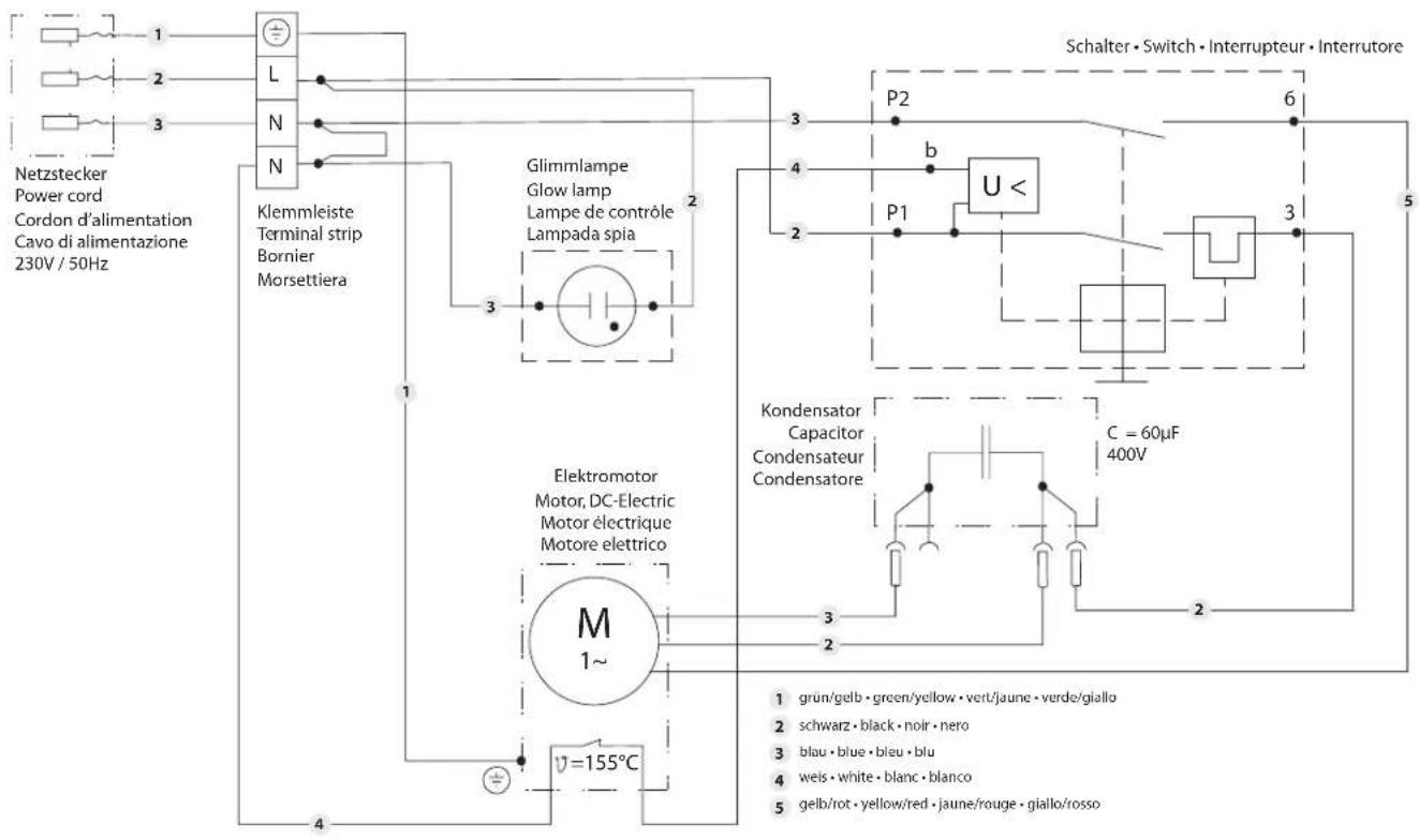
HC 970
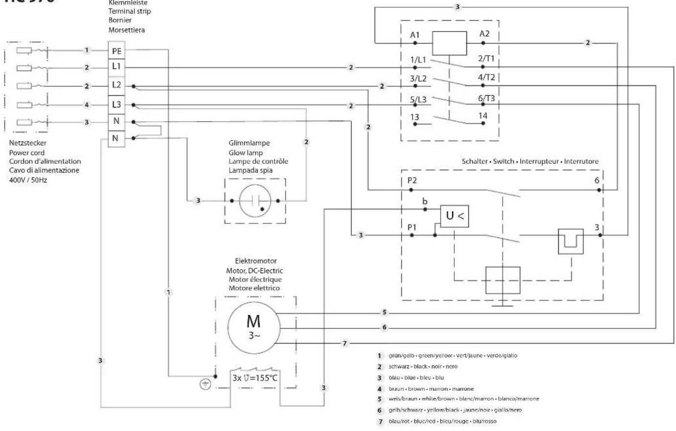
D
Division Professional Finishing
Otto Lilienthal Strasse 18
88677 Markdorf
Important notes on product liability
As a result of an EC regulation being effective as from January 1, 1990, the manufacturer shall only be liable for his product if all parts come from him or are released by him, and if the devices are properly mounted and operated.
If the user applies outside accessories and spare parts, the manufacturer's liability can fully or partially be inapplicable; in extreme cases usage of the entire device can be prohibited by the competent authorities (employer's liability insurance association and factory inspectorate division).
Only the usage of original WAGNER accessories and spare parts guarantees that all safety regulations are observed.
3+2 years guarantee for professional finishing
Wagner professional guarantee
(Status 01.02.2009)
1. Scope of guarantee
All Wagner professional colour application devices (hereafter referred to as products) are carefully inspected, tested and are subject to strict checks under Wagner quality assurance. Wagner exclusively issues extended guarantees to commercial or professional users (hereafter referred to as "customer") who have purchased the product in an authorised specialist shop, and which relate to the products listed for that customer on the Internet under www.wagner-group.com/profi-guarantee.
The buyer's claim for liability for defects from the purchase agreement with the seller as well as statutory rights are not impaired by this guarantee.
We provide a guarantee in that we decide whether to replace or repair the product or individual parts, or take the device back and reimburse the purchase price. The costs for materials and working hours are our responsibility. Replaced products or parts become our property.
2. Guarantee period and registration
The guarantee period amounts to 36 months. For industrial use or equal wear, such as shift operations in particular, or in the event of rentals it amounts to 12 months.
Systems driven by petrol or air are also guaranteed for a 12 month period.
The guarantee period begins with the day of delivery by the authorised specialist shop. The date on the original purchase document is authoritative.
For all products bought in authorised specialist shops from 01.02.2009 the guarantee period is extended to 24 months providing the buyer of these devices registers in accordance with the following conditions within 4 weeks of the day of delivery by the authorised specialist shop.
Registration can be completed on the Internet under www.wagner-group.com/profi-guarantee. The guarantee certificate is valid as confirmation, as is the original purchase document that carries the date of the purchase. Registration is only possible if the buyer is in agreement with having the data being stored that is entered during registration.
When services are carried out under guarantee the guarantee period for the product is neither extended nor renewed.
Once the guarantee period has expired, claims made against the guarantee or from the guarantee can no longer be enforced.
3. Handling
If defects can be seen in the materials, processing or performance of the device during the guarantee period, guarantee claims must be made immediately, or at the latest within a period of 2 weeks.
The authorised specialist shop that delivered the device is entitled to accept guarantee claims. Guarantee claims may also be made to the service centres named in our operating instructions. The product has to be sent without charge or presented together with the original purchase document that includes details of the purchase date and the name of the product. In order to claim for an extension to the guarantee, the guarantee certificate must be included.
The costs as well as the risk of loss or damage to the product in transit or by the centre that accepts the guarantee claims or who delivers the repaired product, are the responsibility of the customer.
4. Exclusion of guarantee
Guarantee claims cannot be considered
- for parts that are subject to wear and tear due to use or other natural wear and tear, as well as defects in the product that are a result of natural wear and tear, or wear and tear due to use. This includes in particular cables, valves, packaging, jets, cylinders, pistons, means-carrying housing components, filters, pipes, seals, rotors, stators, etc. Damage due to wear and tear that is caused in particular by sanded coating materials, such as dispersions, plaster, putty, adhesives, glazes, quartz foundation.
- in the event of errors in devices that are due to non-compliance with the operating instructions, unsuitable or unprofessional use, incorrect assembly and/or commissioning by the buyer or by a third party, or utilisation other than is intended, abnormal ambient conditions, unsuitable coating materials, unsuitable operating conditions, operation with the incorrect mains voltage supply/frequency, over-operation or defective servicing or care and/or cleaning.
- for errors in the device that have been caused by using accessory parts, additional components or spare parts that are not original Wagner parts.
- for products to which modifications or additions have been carried out.
- for products where the serial number has been removed or is illegible
- for products to which attempts at repairs have been carried out by unauthorised persons.
- for products with slight deviations from the target properties, which are negligible with regard to the value and usability of the device.
- for products that have been partially or fully taken apart.
5. Additional regulations.
The above guarantees apply exclusively to products that have been bought by authorised specialist shops in the EU, CIS, Australia and are used within the reference country.
If the check shows that the case is not a guarantee case, repairs are carried out at the expense of the buyer.
The above regulations manage the legal relationship to us concludingly. Additional claims, in particular for damages and losses of any type, which occur as a result of the product or its use, are excluded from the product liability act except with regard to the area of application.
Claims for liability for defects to the specialist trader remain unaffected. German law applies to this guarantee. The contractual language is German. In the event that the meaning of the German and a foreign text of this guarantee deviate from one another, the meaning of the German text has priority.
J. Wagner GmbH
Division Professional Finishing
Otto Lilienthal Strasse 18
88677 Markdorf
Federal Republic of Germany
F
Division Professional Finishing
Otto Lilienthal Strasse 18
88677 Markdorf
Division Professional Finishing
Otto Lilienthal Strasse 18
88677 Markdorf
| D | GB F1 | |||||
| J. Wagner Gmbh Otto Lilienthal-Sr.18 D-88677 Markdorff | ||||||
| WAGNER | ||||||
| CE Konformittelverklaaring | CE Konformittelverklaaring | CE Forsarkan | CE Decalacion de conormalidad por la presente, decalamos que la Alises equipo de purvanzacion de alta presgio. Com a presiene, decalamos que o Parteiro de pulvenzagao conormalidade | CE Decalacao de alta presgio. Com a presiene, decalamos que o Parteiro de pulvenzagao conormalidade por la presente, decalamos que la Alises equipo de purvanzacion de alta presgio. Com a presiene, decalamos que o Parteiro de pulvenzagao conormalidade por la presente, decalamos que la Alises equipo de purvanzacion de alta presgio. Com a presiene, decalamos que o Parteiro de pulvenzagao conormalidade por la presente, decalamos que la Alises equipo de purvanzacion de alta presgio. Com a presiene, decaramos que o Parteiro de pulvenzagao conormalidade por la presente, decalamos que la Alises equipo de purvanzacion de alta presgio. Com a presiene, decaramos que o Parteiro de pulvenzagao conormalidade por la presente, decaramos que la Alises equipo de purvanzacion de alta presgio. Com a presiene, decaramos que o Parteiro de pulvenzagao conormalidade por la presente, decaramos que la Alises equipo de purvanzacion de alta presgio. Com a presiene, decaramos que o Parteiro de pulvenzagao conormalidade por la presente, decaramos que la Alises equipo de purvanzacion en alta presgio. Com a presiene, decaramos que lo presgio. Com a presiene, decaramos que lo presgio. Com a presiene, decaramos que lo presgio. Com a presiene, decaramos que lo presgio. Com a presiene, decaramos que lo presgio. Com a presiene, decaramos que lo presgio. Com a presiene, decaramos que lo presgio. Com a presiene, decaramos que lo presgio. Com a presiene, de untrusive. Com a presiene, decaramos que lo presgio. Com a presiene, decaramos que lo presgio. Com a presiene, decaramos que lo presgio. Com a presiene, decaramos que lo presgio. Com a presiene, decaramos que lo presgio. Com a presiene, decaramos que lo presgio. Com a presiene, decaramos que lo presgio. Com a presiene, decaramo. Com a presiene, decaramos que lo presgio. Com a presiene, decaramos que lo presgio. Com a presiene, decaramos que lo presgio. Com a presiene, decaramos que lo presgio. Com a presiene, decaramos que lo presgio. Com a presiene, decaramos que lo presgio. Com a presiene, decaramos que lo presgio. Com a presiene, decaramas que lo presgio. Com a presiene, decaramos que lo presgio. Com a presiene, decaramos que lo presgio. Com a presiene, decaramos que lo presgio. Com a presiene, decaramos que lo presgio. Com a presiene, decaramos que lo presgio. Com a presiene, decaramos que lo presgio. Com a presiene, decaramos que lo presgio. Com a presene, decaramos que lo presgio. Com a presene, decaramos que lo presgio. Com a presene, decaramos que lo presgio. Com a presene, decaramos que lo presgio. Com a presene, decaramos que lo presgio. Com a presene, decaramos que lo presgio. Com a presene, decaramos que lo presgio. Com a presene, decaramos que lo presgio, Com a presene, decaramos que lo presgio. Com a presene, decaramos que lo presgio. Com a presene, decaramos que lo presgio. Com a presene, decaramos que lo presgio. Com a presene, decaramos que lo presgio. Com a presene, decaramos que lo presgio. Com a presene, decaramos que lo presgio. Com a presene, decaramos that are not satisfied with the 2006/42 EC andentd. I sandelstedh. in het bijzondere: Gebuikke geharmonieserde normen, Harmoniserde standarder, der lev anvend. I sandelstedh. in het bijzondere: Gebuikke geharmonieserde normen, Harmoniserde standarder, der lev anvend. I sandelstedh. in het bijzondere: Gebuikke geharmonieserde normen, Harmoniserde standarder, der lev anvend. I sandelstedh. in het bijzondere: Gebuikke geharmonieserde normen, Mechanische standarder, der lev anvend. I sandelstedh. in het bijzondere: Gebuikke geharmonieserde normen, Mechanische standarder, der lev anvend. I sandelstedh. in het bijzondere: Gebuikke geharmonieserde normen, Mechanische standarder, der lev anvend. I sandelstedh. in het bijzondere: Gebuikke gehamnische standarder, der lev anvend. I sandelstedh. in het bijzondere: Gebuikke gehamnische standarder, der lev anvend. I sandelstedh. in het bijzondere: Gebuikke gehamnische standarder, der lev anvend. I sandelstedh. in het bijzondere: Gebuikke gehamnische standarder, der lev anv end. I sandelstedh. in het bijzondere: Gebuikke gehamnische standarder, der lev anv end. I sandelstedh. in het bijzondere: Gebuikke gehamnische standarder, der lev anv end. I sandelstedh. in het bijzondere: Gebuikke gehamnische standarder, der lev anv end. I sandelstedh. in hetbij zondere: Gebuikke gehamnische standarder, der lev anv end. I sandelstedh. in het bijzondere: Gebuikke gehamnische standarder, der lev anv end. I sandelstedh. in het bijzondere: Gebuikke gehamnische standarder, der lev anv end. I sandelstedh. in het bijzondere: Gebuikke gehamnischen standarder, der lev anv end. I sandelstedh. in het bijzondere: Gebuikke gehamnischen standarder, der lev anv end. I sandelstedh. in het bijzondere: Gebuikke gehamnischen standarder, der lev anv end. I sandelstedh. in het bijzondere: Gebuikke gehamnischen standarder, der lev anv end, I sandelstedh. in het bijzondere: Gebuikke gehamnischen standarder, der lev anv end. I sandelstedh. in het bijzondere: Gebuikke gehamnischen standarder, der lev anv end. I sandelstedh. in het bijzondere: Gebuikke gehamnischen standarder, der lev anv end. I sandelstedh. in het bij zondere: Gebuikke gehamnischen standarder, der lev anv end. I sandelstedh. in het bij zondere: Gebuikke gehamnischen standarder, der lev anv end. I sandelstedh. in het bij zondere: Gebuikke gehamnischen standarder, der lev anv end. I sandelstedh. in het bij zondere: Gebuikke gehamnischere normen, Harmonisder standarder, der lev anv end. I sandelstedh. in het bijzondere: Gebuikke gehamnische standarder, der lev anv end. I sandelstedh. in het bijzondere: Gebuikke gehamnische standarder, der lev anv end. I sandelstedh. in het bijzondere: Gebuikke gehamnische standarder, der lev anv end, I sandelstedh. in het bijzondere: Gebuikke gehamnische standarder, der lev anv end. I sandelstedh. in het bijzondere: Gebuikke gehamnische standarder, der lev anv end. I sandelstedh. in het bijzondere: Gebuikke gehamnische standarder, der lev anv end. I sandelstedh. in het bij zondere: Gebuikke gehamnische standarder, der lev anv end. I sandelstedh. in het bij zondere: Gebuikke gehamnische standarder, der lev anv end. I sandelstedh. in het bij zondere: Gebuikke gehamnische standarder, der lev anv end. I sandelstedh. in het bij zondere: Gebuikke gehamnischen standarder, der lev anv end. I sandelstedh. in het bij zondere: Gebuikke gehamnischen standarder, der lev anv end. I sandelstedh. in het bij zondere: Gebuikke gehamnischen standarder, der lev anv end, I sandelstedh. in het bij zondere: Gebuikke gehamnischen standarder, der lev anv end. I sandelstedh. in het bij zondere: Gebuikke gehamnischen standarder, der lev anv end. I sandelstedh. in het bij zondere: Gebuikke gehamnischen standarder, der lev anv end. I sandelstedh. in het bijzondere: Gebuikke gehamnischen standarder, der lev anv end. I sandelstedh. in het bijzondere: Gebuikke gehamnischen standarder, der lev anv end. I sandelstedh. in het bijzondere: Gebuikke gehamnische standarder, der lev anv end. I sandelstedh. in het bijzondere: Gebuikke gehamnische standarder, der lev anv end. I sandelstedh. in het bijzondere: Gebuikke gehamnische standarder, der lev anv end; I don't be able to be able to be able to be able to be able to be able to be able to be able to be able to be able to be able to be able to be able to be able to be able to be able to be able to be able to be able to be able to be able to be able to be able to be able to be able to be able to be able to be able to be able to be able to be able to be able to be able to be able tobe able to be able to be able to be able to be able to be able to be able to be able to be able to be able to be able to be able to be able to be able to be able to be able to be able to be able to be able to be able to be able to be able to be able to be able to be able to be able to be able to be able to be able to be able to be able to be able to be able to beable to be able to be able to be able to be able to be able to be able to be able to be able to be able to be able to be able to be able to be able to be able to be able to be able to be able to be able to be able to be able to be able to be able to be able to be able to be able to be able to be able to be able to be able to be able to be able to be able to be ableto be able to be able to be able to be able to be able to be able to be able to be able to be able to be able to be able to be able to be able to be able to be able to be able to be able to be able to be able to be able to be able to be able to be able to be able to be able to be able to be able to be able to be able to be able to be able to be able to be able to bedunlare: or by the rest of the rest of the rest of the rest of the rest of the rest of the rest of the rest of the rest of the rest of the rest of the rest of the rest of the rest of the rest of the rest of the rest of the rest of the rest of the rest of the rest of the rest of the rest of the rest of the rest of the rest of the rest of the rest of the rest of the rest of the rest of the rest of the rest of the rest ofthe rest of the rest of the rest of the rest of the rest of the rest of the rest of the rest of the rest of the rest of the rest of the rest of the rest of the rest of the rest of the rest of the rest of the rest of the rest of the rest of the rest of the rest of the rest of the rest of the rest of the rest of the rest of the rest of the rest of the rest of the rest of the rest of the rest of the Rest of the rest of the rest of the rest of the rest of the rest of the rest of the rest of the rest of the rest of the rest of the rest of the rest of the rest of the rest of the rest of the rest of the rest of the rest of the rest of the rest of the rest of the rest of the rest of the rest of the rest of the rest of the rest of the rest of the rest of the rest of the rest of the rest of the restof the rest of the rest of the rest of the rest of the rest of the rest of the rest of the rest of the rest of the rest of the rest of the rest of the rest of the rest of the rest of the rest of the rest of the rest of the rest of the rest of the rest of the rest of the rest of the rest of the rest of the rest of the rest of the rest of the rest of the rest of the rest of the rest of the rest of they are not satisfied with the rest of the rest of the rest of the rest of the rest of the rest of the rest of the rest of the rest of the rest of the rest of the rest of the rest of the rest of the rest of the rest of the rest of the rest of the rest of the rest of the rest of the rest of the rest of the rest of the rest of the rest of the rest of the rest of the rest of the rest of the rest of the rest of the rest of it are not satisfied with the rest of the rest of the rest of the rest of the rest of the rest of the rest of the rest of the rest of the rest of the rest of the rest of the rest of the rest of the rest of the rest of the rest of the rest of the rest of the rest of the rest of the rest of the rest of the rest of the rest of the rest of the rest of the rest of the rest of the rest of the rest of the restof the rest of they are not satisfied with the rest of the rest of the rest of the rest of the rest of the rest of the rest of the rest of the rest of the rest of the rest of the rest of the rest of the rest of the rest of the rest of the rest of the rest of the rest of the rest of the rest of the rest of the rest of the rest of the rest of the rest of the rest of the rest of the rest of the rest of the Rest of the rest of the rest of they are not satisfied with the rest of the rest of the rest of the rest of the rest of the rest of the rest of the rest of the rest of the rest of the rest of the rest of the rest of the rest of the rest of the rest of the rest of the rest of the rest of the rest of the rest of the rest of the rest of the rest of the rest of the rest of the rest of the rest of the rest of they are not satisfied with the rest of the rest of the Rest of the rest of the rest of the rest of the rest of the rest of the rest of the rest of the rest of the rest of the rest of the rest of the rest of the rest of the rest of the rest of the rest of the rest of the rest of the rest of the rest of the rest of the rest of the rest of the rest of the rest of the rest of the rest of the rest of the rest of the rest of they are not satisfied with the rest of they are not satisfied with the rest of they are not satisfied with the rest of they are not satisfied with the rest of they are not satisfied with the rest of they are not satisfied with the rest of they are not satisfied with the rest of they are not satisfied with the rest of they are not satisfied with the rest of they are not satisfied with the rest of they are not satisfied with the rest of they are not satisfied with the rest of they are not satisfied with the rest of the rest of they are not satisfied with the rest of they are not satisfied with the rest of they are not satisfied with the rest of they are not satisfied with the rest of they are not satisfied with the rest of they are not satisfied with the rest of they are not satisfied with the rest of they are not satisfied with the rest of they are not satisfied with the rest of they are not satisfied with the rest of they are not satisfied with the rest of they are not satisfied withthe rest of the rest of the rest of the rest of the rest of the rest of the rest of the rest of the rest of the rest of the rest of the rest of the rest of the rest of the rest of the rest of the rest of the rest of the rest of the rest of the rest of the rest of the rest of the rest of the rest of the rest of the rest of the rest of the rest of the rest of the rest of the rest of the rest of they were not satisfied with the rest of they are not satisfied with the rest of they are not satisfied with the rest of they are not satisfied with the rest of they are not satisfied with the rest of they are not satisfied with the rest of they are not satisfied with the rest of they are not satisfied with the rest of they are not satisfied with the rest of they are not satisfied with the rest of they are not satisfied with the rest of they are not satisfied with the rest of they are not satisfied withthe rest of they are not satisfied with the rest of they are not satisfied with the rest of they are not satisfied with the rest of they are not satisfied with the rest of they are not satisfied with the rest of they are not satisfied with the rest of they are not satisfied with the rest of they are not satisfied with the rest of they are not satisfied with the rest of they are not satisfied with the rest of they are not satisfied with the rest of they are not satisfied with the rest of theyare not satisfied with the rest of they are not satisfied with the rest of they are not satisfied with the rest of they are not satisfied with the rest of they are not satisfied with the rest of they are not satisfied with the rest of they are not satisfied with the rest of they are not satisfied with the rest of they are not satisfied with the rest of they are not satisfied with the rest of they are not satisfied with the rest of they are not satisfied with the rest of they are not satisfied with they are not satisfied with the rest of they are not satisfied with the rest of they are not satisfied with the rest of they are not satisfied with the rest of they are not satisfied with the rest of they are not satisfied with the rest of they are not satisfied with the rest of they are not satisfied with the rest of they are not satisfied with the rest of they are not satisfied with the rest of they are not satisfied with the rest of they are not satisfied with the rest of they are notatisfied with the rest of their bestone and the rest of their bestone and the rest of their bestone and the rest of their bestone and the rest of their bestone and the rest of their bestone and the rest of their bestone and the rest of their bestone and the rest of their bestone and the rest of their bestone and the rest of their bestone and the rest of their bestone and the rest of their bestone and the rest of their bestone and the rest of their bestone and the bestone and the bestone and the bestone and the bestone and the bestone and the bestone and the bestone and the bestone and the bestone and the bestone and the bestone and the bestone and the bestone and the bestone and the bestone and the bestone and the bestone and the bestone and the bestone and the bestone and the bestone and the bestone and the bestone and the bestone and the bestone and then be able to be able to be able to be able to be able to be able to be able to be able to be able to be able to be able to be able to be able to be able to be able to be able to be able to be able to be able to be able to be able to be able to be able to be able to be able to be able to be able to be able to be able to be able to be able to be able to be able to have been taken from the rest of their bestone and the rest of their bestone and the rest of their bestone and the rest of their bestone and the rest of their bestone and the rest of their bestone and the rest of their bestone and the rest of their bestone and the rest of their bestone and the rest of their bestone and the rest of their bestone and the rest of their bestone and the rest of their bestone and the rest of their bestone and the Rest of their bestone and the Rest of their bestone and the Rest of their bestone and the Rest of their bestone and the Rest of their bestone and the Rest of their bestone and the Rest of their bestone and the Rest of their bestone and the Rest of their bestone and the Rest of their bestone and the Rest of their bestone and the Rest of their bestone and the Rest of their bestone and the Rest of their bestone and the Rest of its bestone and the Rest of its bestone and the Rest of its bestone and the Rest of its bestone and the Rest of its bestone and the Rest of its bestone and the Rest of its bestone and the Rest of its bestone and the Rest of its bestone and the Rest of its bestone and the Rest of its bestone and the Rest of its bestone and the Rest of its bestone and the Rest of its bestone and the Rest of its best one and the Rest of its bestone and the Rest of its bestone and the Rest of its bestone and the Rest of its bestone and the Rest of its bestone and the Rest of its bestone and the Rest of its bestone and the Rest of its bestone and the Rest of its bestone and the Rest of its bestone and the Rest of its bestone and the Rest of its bestone and the Rest of its bestone and the Rest of its bestone and then be able to be able to be able to be able to be able to be able to be able to be able to be able to be able to be able to be able to be able to be able to be able to be able to be able to be able to be able to be able to be able to be able to be able to be able to be able to be able to be able to be able to be able to be able to be able to be ableto be able to have been taken from the rest of their bestone and the rest of their bestone and the rest of their bestone and the rest of their bestone and the rest of their bestone and the rest of their bestone and the rest of their bestone and the rest of their bestone and the rest of their bestone and the rest of their bestone and the rest of their bestone and the rest of their bestone and the rest of their bestone and the Rest of their bestone and the rest of their bestone and the rest of their bestone and the rest of their bestone and the rest of their bestone and the rest of their bestone and the rest of their bestone and the rest of their bestone and the rest of their bestone and the rest of their bestone and the rest of their bestone and the rest of their bestone and the rest of their bestone and the rest of their bestone and the rest of its bestone and the restone and then be able to be able to be able to be able to be able to be able to be able to be able to be able to be able to be able to be able to be able to be able to be able to be able to be able to be able to be able to be able to be able to be able to be able to be able to be able to be able to be able to be able to be able to be able to be able to be able tobe able to have been taken from the rest of their bestone and the restone and then be able to be able to be able to be able to be able to be able to be able to be able to be able to be able to be able to be able to be able to be able to be able to be able to be able to be able to be able to be able to be able to be able to be able to be able to be able to be able to be able to be able to be able to be able to beable to have been taken from the rest of their bestone and the restone and then be able to be able to be able to be able to be able to be able to be able to be able to be able to be able to be able to be able to be able to be able to be able to be able to be able to be able to be able to be able to be able to be able to be able to be able to be able to be able to be able to beable to have been taken from the rest of their bestone and then be able to be able to be able to be able to be able to be able to be able to be able to be able to be able to be able to be able to be able to be able to be able to be able to be able to be able to be able to be able to be able to be able to be able to be able to be able to be able to be able to be able to be able to be able to be able to be able-to be able to have been taken from the rest of their bestone and then be able to be able to be able to be able to be able to be able to be able to be able to be able to be able to be able to be able to be able to be able to be able to be able to be able to be able to be able to be able to be able to be able to be able to be able to be able to be able to be able to be able to be able-to be able to have been taken from the rest of their best one and then be able to be able to be able to be able to be able to be able to be able to be able to be able to be able to be able to be able to be able to be able to be able to be able to be able to be able to be able to be able to be able to be able to be able to be able to be able to be able to be able to be able to be able to be able to be able to be able to beable to have been taken from the restof their | ||
D
Entsorgungshinweis:
In observance of the European Directive 2002/96/EC on waste electrical and electronic equipment and implementation in accordance with national law, this product is not to be disposed of together with household waste material but must be recycled in an environmentally friendly way!
Wagner or one of our dealers will take back your used Wagner waste electrical or electronic equipment and will dispose of it for you in an environmentally friendly way. Please ask your local Wagner service centre or dealer for details or contact us direct.


F


- HEAVYCOAT (HC)
- · 970
- Warnung!
- Krantransport
- Inbetriebnahme
- Transportposition (Abb. 9)
- München
- Nürnberg
- Markdorf – Zentrale
- Be safety conscious!
- Contents
- Page
- Safety regulations for Airless spraying
- Explanation of symbols used
- HAZARD: INJECTION INJURY
- PREVENTION:
- HAZARD: HIGH PRESSURE HOSE
- HAZARD: EXPLOSION OR FIRE
- Safety precautions
- HAZARD: HAZARDOUS VAPORS
- HAZARD: GENERAL
- Electric Safety
- Work or repairs at the electrical equipment:
- Gasoline Engine Safety
- Setting up on uneven surfaces
- General view of application
- Application
- Examples of objects to be sprayed
- Coating materials
- Processible coating materials
- HC 950-SSP
- HC 970-SSP
- Filtering
- Viscosity
- Two-component coating material
- Coating materials with sharp-edged additional materials
- Description of unit
- Airless process
- Functioning of the unit
- Illustration legend for gasoline HC units
- Illustration of gasoline HC units
- Illustration legend for electric HC units
- Illustration of electric HC units
- Operating Temperature
- Relative Humidity
- Altitude
- Transportation and Storage
- Transport
- Handle
- Transport in vehicle
- Crane transport
- Starting operation
- Changing the material feed pump position
- Transport position (fig. 9)
- Operating position I (fig. 10)
- Operating position II (fig. 11)
- High-pressure hose, spray gun and separating oil
- Gasoline engine (gas units only)
- Connection to the mains (electric units only)
- Flushing preserving fluid during initial start-up
- Taking the unit into operation with coating material
- Spraying technique
- Handling the high-pressure hose
- Interruption of work
- Cleaning the unit (shutting down)
- Cleaning the unit from the outside
- Cleaning the high-pressure filter
- Disassembly
- Always replace O-ring (6) after removal.
- Assembly
- Cleaning Airless spray gun
- Intake filter in Airless spray gun (fig. 16)
- Dismounting
- Mounting
- Servicing
- General servicing
- Checking the oil level in the hydraulic oil tank
- Oil and oil filter change of the hydraulic oil pump
- High-pressure hose
- Appendix
- Selection of tip
- Some rules for this:
- Servicing and cleaning of Airless hard-metal tips
- Standard tips
- The following points must be observed to keep the tip clean and ready for use:
- Spray gun accessories
- Tip extension with slewable knee joint (without tip)
- Tip extension
- Airless tip table
- 2Speed Tip table
- Mise en service
- Position de transport (fig. 9)
- D
- Important notes on product liability
- 3+2 years guarantee for professional finishing
- Scope of guarantee
- Guarantee period and registration
- Handling
- Exclusion of guarantee
- Additional regulations.
- Wagner GmbH
- F
- Division Professional Finishing
- Otto Lilienthal Strasse 18
- Markdorf
- Entsorgungshinweis:
Brand : WAGNER
Model : HeavyCoat 970 E SSP
Category : Paint spray