DCST925 - Grass trimmer DEWALT - Free user manual and instructions
Find the device manual for free DCST925 DEWALT in PDF.

| Product type | Cordless string trimmer |
| Brand | DeWalt |
| Model | DCST925 |
| Power source | DeWalt 20V max* lithium-ion battery (not included) |
| Rated voltage | 18 V (20 V max* nominal) |
| Cutting line diameter | 2.0 mm (0.080 in) |
| Cutting width | 330 mm (13 in) |
| Recommended safety distance | 30 m (100 ft) from people and pets |
| Variable speed | Yes, variable speed trigger |
| Auxiliary handle | Yes, adjustable |
| Guard | Yes, fixed (extended guard optional) |
| Line feed | Bump feed on ground |
| Intended use | Professional trimming (not edging) |
| Weight (approx.) | 2.3 kg (without battery) |
| Overall length | Approx. 120 cm (assembled) |
| Warranty | 3-year limited, 1-year free service |
| Spare parts available | Spool (DWO1DT801/DWO1DT802), guard (N688823) |
| Cleaning | Damp cloth with mild soap, do not immerse |
| Charging temperature | 18 °C to 24 °C (65 °F to 75 °F) |
| Safety standards | ANSI Z87.1 eye protection required |
Frequently Asked Questions - DCST925 DEWALT
User questions about DCST925 DEWALT
0 question about this device. Answer the ones you know or ask your own.
Ask a new question about this device
Download the instructions for your Grass trimmer in PDF format for free! Find your manual DCST925 - DEWALT and take your electronic device back in hand. On this page are published all the documents necessary for the use of your device. DCST925 by DEWALT.
USER MANUAL DCST925 DEWALT
Definitions: Safety Alert Symbols and Words
This instruction manual uses the following safety alert symbols and words to alert you to hazardous situations and your risk of personal injury or property damage.

NOTICE: Indicates a practice not related to personal injury which, if not avoided, may result in property damage.
Fig. A
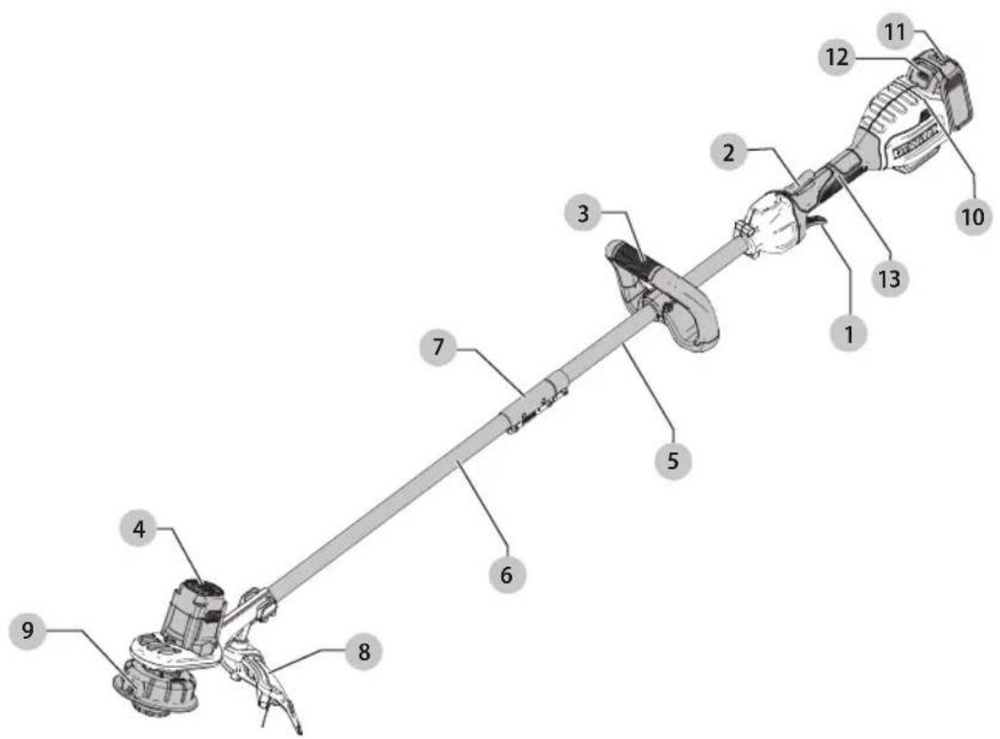
1 Variable speed trigger
2 Lock-off lever
3 Auxiliary handle
4 Motor housing
5 Upper trimmer pole
6 Lower trimmer pole
7 Pole bracket
8 Guard
9 Spool housing
10 Battery housing
11 Battery pack
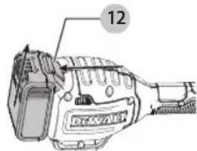
12 Battery release button
13 Handle
WARNING! Read all safety warnings
and all instructions. Failure to follow the warnings and instructions may result in electric shock, fire and/or serious injury.

WARNING: To reduce the risk of injury, read the instruction manual.
If you have any questions or comments about this or any DEWALTtool, call us toll free at: 1-800-4-DEWALT(1-800-433-9258).
English
Important Safety Warnings

To reduce risk of injury:
- Before any use, be sure everyone using this unit reads and understands all safety instructions and other information contained in this manual.
- Save these instructions and review frequently.

When using electric gardening appliances, basic safety precautions should always be followed to reduce risk of fire, electric shock, and personal injury, including the following.
READ ALL INSTRUCTIONS
-
Avoid Dangerous Environments – DO NOT use appliances in damp or wet locations. DO NOT operate portable electric appliances in gaseous or explosive atmospheres. Motors in these appliances normally spark, and the sparks might ignite fumes.
-
Don't Use In Rain.
-
Keep All Bystanders Away – at a safe distance from work area, especially children.
-
Dress Properly – Do not wear loose clothing or jewelry. They can be caught in moving parts. Gloves and substantial rubber soled footwear are recommended when working outdoors. Wear protective hair covering to contain long hair.
-
Always Wear Eye Protection – Wear ANSI Z87.1 approved eye protection at all times when battery is installed. Also use face or dust mask. Safety glasses are available at extra cost at your localDEWALTService Center or authorized service facility.
-
Use Right Appliance – Do not use appliance for any job except that for which it is intended.
-
Avoid Accidentally Starting – Don't carry with finger on trigger when battery is installed.
-
Don't Force Appliance – It will do the job better and with less likelihood of a risk of injury at the rate for which it was designed.
-
Don't Overreach – Keep proper footing and balance at all times.
-
Stay Alert – Watch what you are doing. Use common sense. DO NOT operate while under the influence of alcohol or drugs, or when you are tired or ill.
-
Disconnect Appliance – Remove the battery when not in use, before servicing, when changing accessories such as blades, and the like.
-
Store Idle Appliances Indoors – When not in use, appliances should be stored indoors in dry, and high or locked-up place – out of reach of children.
-
Maintain Appliance With Care – Keep cutting edge sharp and clean for best performance and to reduce the risk of injury. Follow instructions for lubricating and changing accessories. Inspect appliance cord periodically, and if damaged, have it repaired by an authorized service facility. Inspect extension cords periodically and replace
if damaged. Keep handles dry, clean, and free from oil and grease.
- Check Damaged Parts – Before further use of the appliance, a guard or other part that is damaged should be carefully checked to determine that it will operate properly and perform its intended function. Check for alignment of moving parts, binding of moving parts, breakage of parts, mounting, and any other condition that may affect its operation. A guard or other part that is damaged should be properly repaired or replaced by an authorized service center unless indicated elsewhere in this manual.
- Damage to Unit – If you strike or become entangled with a foreign object, stop appliance immediately, remove battery, check for damage and have any damage repaired before further operation is attempted.
- Guard - Do not use this appliance without guard attached. Keep guards in place and in working order.
- DO NOT immerse appliance in water or squirt it with a hose. DO NOT allow any liquid to get inside it. If appliance does get wet, allow to dry for a minimum of 48 hours.
- DO NOT store the appliance on or adjacent to fertilizers or chemicals.
- DO NOT clean with a pressure washer.
- DO NOT charge appliance in rain, or in wet locations.
Specific Warnings for String Trimmers

and is not intended to be used for edging.
- Don't operate the appliance when barefoot or wearing open sandals.
- Wear heavy long pants to protect your legs.
- MAKE SURE that other persons and pets are at least 100 feet (30 m) away.
- Keep face, hands and feet clear of rotating nylon line at all times.
- The rotating line performs a cutting function. Use care when trimming around screens and desirable plantings.
• To reduce the risk of rebound (ricochet) injury, work going away from any nearby solid object such as wall, steps, large stone, tree, etc. Use great care when working close to solid objects and where necessary, do trimming by hand.
Additional Safety Warnings

Never modify the power
tool or any part of it. Damage or personal injury could result.

Use only DEWALT replacement spots and line. Using any other manufacturer's line can reduce performance, damage the trimmer or cause personal injury.
Your trimmer uses 0.080" (2.0 mm) diameter line. Do not use other size lines. This can degrade performance, cause damage to the unit or injury.
WARNING:
WARNING. Do not use appliance if the switch trigger does not turn the appliance on or off. Any appliance that can not be controlled with the switch trigger is dangerous and must be repaired.
WARNING:
WARNING. Some dust created by this product contains chemicals known to the State of California to cause cancer, birth defects or other reproductive harm. Some examples of these chemicals are:
• compounds in fertilizers
• compounds in insecticides, herbicides and pesticides
• arsenic and chromium from chemically treated lumber
To reduce your exposure to these chemicals, wear approved safety equipment such as dust masks that are specially designed to filter out microscopic particles.
The label on your appliance may include the following symbols. The symbols and their definitions are as follows:
V....volts
Hz ..... hertz
min......minutes
or DC.....direct current
Class I Construction (grounded)
.../min.....per minute
BPM.....beats per minute
n_0 .....no load speed n .....rated speed
earthing terminal
⚠️ ____ safety alert symbol
△......visible radiation
wearrespiratory protection
weareye
protection
O....wearhearing
protection
readall
documentation
BATTERIES AND CHARGERS
The battery pack is not fully charged out of the carton. Before using the battery pack and charger, read the safety instructions below and then follow charging procedures outlined. When ordering replacement battery packs, be sure to include the catalog number and voltage. Your tool uses a DEWALTcharger. Be sure to read all safety instructions before using your charger. Consult the chart at the end of this manual for compatibility of chargers and battery packs.
READ ALL INSTRUCTIONS
Important Safety Instructions for All Battery Packs
WARNING:
Read all safety
warnings and all instructions for the battery pack, charger and power tool. Failure to follow the warnings and instructions may result in electric shock, fire and/or serious injury.
- Do not charge or use the battery pack in explosive atmospheres, such as in the presence of flammable liquids, gases or dust. Inserting or removing the battery pack from the charger may ignite the dust or fumes.
- NEVER force the battery pack into the charger. DO NOT modify the battery pack in any way to fit into a non-compatible charger as battery pack may rupture causing serious personal injury. Consult the chart at the end of this manual for compatibility of batteries and chargers.
- Charge the battery packs only in designated DEWALTchargers.
• DO NOT splash or immerse in water or other liquids. - Do not store or use the tool and battery pack in locations where the temperature may reach or exceed 104 °F (40 °C) (such as outside sheds or metal buildings in summer). For best life store battery packs in a cool, dry location.
NOTE: Do not store the battery packs in a tool with the trigger switch locked on. Never tape the trigger switch in the ON position.
- Do not incinerate the battery pack even if it is severely damaged or is completely worn out. The battery pack can explode in a fire. Toxic fumes and materials are created when lithium ion battery packs are burned.
- If battery contents come into contact with the skin, immediately wash area with mild soap and water. If battery liquid gets into the eye, rinse water over the open eye for 15 minutes or until irritation ceases. If medical attention is needed, the battery electrolyte is composed of a mixture of liquid organic carbonates and lithium salts.
- Contents of opened battery cells may cause respiratory irritation. Provide fresh air. If symptoms persist, seek medical attention.
WARNING: Burn hazard. Battery liquid may be flammable if exposed to spark or flame.
WARNING:
Fire hazard. Never attempt
to open the battery pack for any reason. If the battery pack case is cracked or damaged, do not insert into the charger. Do not crush, drop or damage the battery pack. Do not use a battery pack or charger that has received a sharp blow, been dropped, run over or damaged in any way (e.g., pierced with a nail, hit with a hammer, stepped on). Damaged battery packs should be returned to the service center for recycling.
ENGLISH
Transportation
WARNING: Fire hazard. Do not store or carry the battery pack so that metal objects can contact exposed battery terminals. For example, do not place the battery pack in aprons, pockets, tool boxes, product kit boxes, drawers, etc., with loose nails, screws, keys, etc. Transporting batteries can possibly cause fires if the battery terminals inadvertently come in contact with conductive materials such as keys, coins, hand tools and the like. The US Department of Transportation Hazardous Material Regulations (HMR) actually prohibit transporting batteries in commerce or on airplanes in carry-on baggage UNLESS they are properly protected from short circuits. So when transporting individual battery packs, make sure that the battery terminals are protected and well insulated from materials that could contact them and cause a short circuit. NOTE: Lithium-ion batteries should not be put in checked baggage.
Shipping the DEWALT FLEXVOLT™ Battery
The DEWALT FLEXVOLT™ battery has two modes: Use and Shipping.
Use Mode: When the FLEXVOLT™ battery stands alone or is in a DEWALT 20V Max* product, it will operate as a 20V Max* battery. When the FLEXVOLT™ battery is in a 60V Max* or a 120V Max* (two 60V Max* batteries) product, it will operate as a 60V Max* battery.
Shipping Mode: When the cap is attached to the FLEXVOLT™ battery, the battery is in Shipping Mode. Strings of cells are electrically disconnected within the pack resulting in three batteries with a lower Watt hour (Wh) rating as compared to one battery with a higher Watt hour rating. This increased quantity of three batteries with the lower Watt hour rating can exempt the pack from certain shipping regulations that are imposed upon the higher Watt hour batteries.
The battery label indicates two Watt hour ratings (see example). Depending on how the battery is shipped, the appropriate Watt hour rating must be used to determine the applicable shipping requirements. If utilizing the shipping cap, the pack will be considered 3 batteries at the Watt hour rating indicated for "Shipping". If shipping without the cap or in a tool, the pack will be considered one battery at the Watt hour rating indicated next to "Use".
Example of Use and Shipping Label Marking
USE: 120 Wh Shipping: 3 x 40 Wh
For example, Shipping Wh rating might indicate 3 x 40 Wh, meaning 3 batteries of 40 Watt hours each. The Use Wh rating might indicate 120 Wh (1 battery implied).
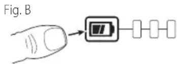
Fuel Gauge Battery Packs (Fig. B)
Some DEWALT battery packs include a fuel gauge which consists of three green LED lights that indicate the level of charge remaining in the battery pack.
The fuel gauge is an indication of approximate levels of charge remaining in the battery pack according to the following indicators:

75–100% charged

51–74% charged

< 50% charged

Pack needs to be charged
To actuate the fuel gauge, press and hold the fuel gauge button. A combination of the three green LED lights will illuminate designating the level of charge left. When the level of charge in the battery is below the usable limit, the fuel gauge will not illuminate and the battery will need to be recharged.
NOTE: The fuel gauge is only an indication of the charge left on the battery pack. It does not indicate tool functionality and is subject to variation based on product components, temperature and end-user application.
For more information regarding fuel gauge battery packs, please call 1-800-4-DeWALT (1-800-433-9258) or visit our website www.dewalt.com.
The RBRC® Seal
The RBRC ^® (Rechargeable Battery Recycling Corporation) Seal on the nickel cadmium, nickel metal hydride or lithium-ion batteries (or battery packs) indicates that the costs to recycle these batteries (or battery packs) at the end of their useful life have already been paid by DEWALT. In some areas, it is illegal to place spent nickel cadmium, nickel metal hydride or lithium-ion batteries in the trash or municipal solid waste stream and the Call 2 Recycle® program provides an environmentally conscious alternative.

Call 2 Recycle, Inc., in cooperation with DEWALT and other battery users, has established the program in the United States and Canada to facilitate the collection of spent nickel cadmium, nickel metal hydride or lithium-ion batteries. Help protect our environment and conserve natural resources by returning the spent nickel cadmium, nickel metal hydride or lithium-ion batteries to an authorized DEWALT service center or to your local retailer for recycling. You may also contact your local recycling center for information on where to drop off the spent battery. RBRC® is a registered trademark of Call 2 Recycle, Inc.
Important Safety Instructions for All Battery Chargers
WARNING: Read all safety
warnings and all instructions for the battery pack, charger and power tool. Failure to follow the warnings and instructions may result in electric shock, fire and/or serious injury.
- DO NOT attempt to charge the battery pack with any chargers other than the ones in this manual.
The charger and battery pack are specifically designed to work together.
• These chargers are not intended for any uses other than charging DEWALTrechargeable batteries.
Any other uses may result in risk of fire, electric shock or electrocution.
- Do not expose the charger to rain or snow.
- Pull by the plug rather than the cord when disconnecting the charger. This will reduce the risk of damage to the electric plug and cord.
- Make sure that the cord is located so that it will not be stepped on, tripped over or otherwise subjected to damage or stress.
- Do not use an extension cord unless it is absolutely necessary. Use of improper extension cord could result in risk of fire, electric shock or electrocution.
- When operating a charger outdoors, always provide a dry location and use an extension cord suitable for outdoor use. Use of a cord suitable for outdoor use reduces the risk of electric shock.
- An extension cord must have adequate wire size (AWG or American Wire Gauge) for safety. The smaller the gauge number of the wire, the greater the capacity of the cable, that is, 16 gauge has more capacity than 18 gauge. An undersized cord will cause a drop in line voltage resulting in loss of power and overheating. When using more than one extension to make up the total length, be sure each individual extension contains at least the minimum wire size. The following table shows the correct size to use depending on cord length and nameplate ampere rating. If in doubt, use the next heavier gauge. The lower the gauge number, the heavier the cord.
Minimum Gauge for Cord Sets
| Volts | Total Length of Cord in Feet (meters) | ||||
| 120 V 25 (7.6) | 50 (15.2) 100 (30.5) 150 (45.7) | ||||
| 240 V 50 (15.2) | 100 (30.5) 200 (61.0) 300 (91.4) | ||||
| Ampere Rating | American Wire Gauge | ||||
| More Than | Not More Than | ||||
| 0 6 18 | 16 16 14 | ||||
| 6 10 18 | 16 14 12 | ||||
| 10 12 | 16 16 14 12 | ||||
| 12 16 14 12 Not Recommended | |||||
- Do not place any object on top of the charger or place the charger on a soft surface that might block the ventilation slots and result in excessive internal heat. Place the charger in a position away from any heat source. The charger is ventilated through slots in the top and the bottom of the housing.
- Do not operate the charger with a damaged cord or plug.
- Do not operate the charger if it has received a sharp blow, been dropped or otherwise damaged in any way. Take it to an authorized service center.
- Do not disassemble the charger; take it to an authorized service center when service or repair is required. Incorrect reassembly may result in a risk of electric shock, electrocution or fire.
- Disconnect the charger from the outlet before attempting any cleaning. This will reduce the risk of electric shock. Removing the battery pack will not reduce this risk.
- NEVER attempt to connect 2 chargers together.
- The charger is designed to operate on standard 120V household electrical power. Do not attempt to use it on any other voltage. This does not apply to the vehicular charger.
WARNING: Shock hazard. Do not allow any liquid to get inside the charger. Electric shock may result.
WARNING:
WARNING. Burn hazard. Do not submerge the battery pack in any liquid or allow any liquid to enter the battery pack. Never attempt to open the battery pack for any reason. If the plastic housing of the battery pack breaks or cracks, return to a service center for recycling.
AUTION:
WALION: Burn hazard. To reduce the risk of injury, charge only DEWALT rechargeable battery packs. Other types of batteries may overheat and burst resulting in personal injury and property damage.
NOTICE:
NOTICE. Under certain conditions, with the charger plugged into the power supply, the charger can be shorted by foreign material. Foreign materials of a conductive nature, such as, but not limited to, grinding dust, metal chips, steel wool, aluminum foil or any buildup of metallic particles should be kept away from the charger cavities. Always unplug the charger from the power supply when there is no battery pack in the cavity. Unplug the charger before attempting to clean.
Charging a Battery (Fig. C)
- Plug the charger into an appropriate outlet before inserting battery pack.
ENGLISH
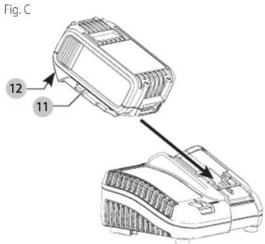
- Insert the battery pack 11 into the charger, making sure the battery pack is fully seated in the charger. The red (charging) light will blink continuously indicating that the charging process has started.
- The completion of charge will be indicated by the red light remaining ON continuously. The battery pack is fully charged and may be used at this time or left in the charger. To remove the battery pack from the charger, push the battery release button 12 on the battery pack and then slide the battery pack out of the charger.
NOTE: To ensure maximum performance and life of lithium-ion battery packs, charge the battery pack fully before first use.
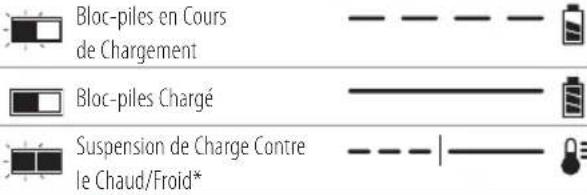
Charger Operation
Refer to the indicators below for the charge status of the battery pack.
DCB107, DCB112, DCB113, DCB115, DCB118, DCB132
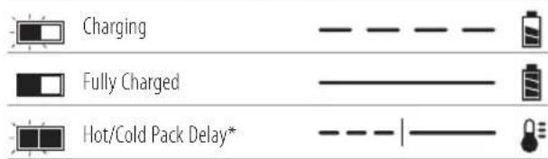
* DCB107, DCB112, DCB113, DCB115, DCB118,
DCB132: The red light will continue to blink, but a yellow indicator light will be illuminated during this operation. Once the battery pack has reached an appropriate temperature, the yellow light will turn off and the charger will resume the charging procedure.
The compatible charger(s) will not charge a faulty battery pack. The charger will indicate faulty battery pack by refusing to light.
NOTE: This could also mean a problem with a charger.
If the charger indicates a problem, take the charger and battery pack to be tested at an authorized service center.
Hot/Cold Pack Delay
When the charger detects a battery pack that is too hot or too cold, it automatically starts a Hot/Cold Pack Delay, suspending charging until the battery pack has reached an appropriate temperature. The charger then automatically switches to the pack charging mode. This feature ensures maximum battery pack life.
A cold battery pack will charge at a slower rate than a warm battery pack. The battery pack will charge at that slower rate throughout the entire charging cycle and will not return to maximum charge rate even if the battery pack warms.
The DCB118 charger is equipped with an internal fan designed to cool the battery pack. The fan will turn on automatically when the battery pack needs to be cooled.
Never operate the charger if the fan does not operate properly or if ventilation slots are blocked. Do not permit foreign objects to enter the interior of the charger.
Electronic Protection System
Li-Ion tools are designed with an Electronic Protection System that will protect the battery pack against overloading, overheating or deep discharge.
The tool will automatically turn off if the Electronic Protection System engages. If this occurs, place the lithium-ion battery pack on the charger until it is fully charged.
Wall Mounting
DCB107, DCB112, DCB113, DCB115, DCB118, DCB132
These chargers are designed to be wall mountable or to sit upright on a table or work surface. If wall mounting, locate the charger within reach of an electrical outlet, and away from a corner or other obstructions which may impede air flow. Use the back of the charger as a template for the location of the mounting screws on the wall. Mount the charger securely using drywall screws (purchased separately) at least 1" (25.4 mm) long, with a screw head diameter of 0.28–0.35" (7–9 mm), screwed into wood to an optimal depth leaving approximately 7/32" (5.5 mm) of the screw exposed. Align the slots on the back of the charger with the exposed screws and fully engage them in the slots.
Charger Cleaning Instructions
WARNING: Shock hazard.
Disconnect the charger from the AC outlet before cleaning. Dirt and grease may be removed from the exterior of the charger using a cloth or soft non-metallic brush. Do not use water or any cleaning solutions.
Important Charging Notes
- Longest life and best performance can be obtained if the battery pack is charged when the air temperature is between 65 °F and 75 °F (18 ° – 24 °C). DO NOT charge the battery pack below +40 °F (+4.5 °C), or above +104 °F (+40 °C). This is important and will prevent serious damage to the battery pack.
- The charger and battery pack may become warm to the touch while charging. This is a normal condition, and does not indicate a problem. To facilitate the cooling of the battery pack after use, avoid placing the charger or battery pack in a warm environment such as in a metal shed or an uninsulated trailer.
- If the battery pack does not charge properly:
a. Check operation of receptacle by plugging in a lamp or other appliance;
English
b. Check to see if receptacle is connected to a light switch which turns power off when you turn out the lights;
c. Move the charger and battery pack to a location where the surrounding air temperature is approximately 65^ F – 75^ F ( 18^ – 24^ C);
d. If charging problems persist, take the tool, battery pack and charger to your local service center.
- The battery pack should be recharged when it fails to produce sufficient power on jobs which were easily done previously. DO NOT CONTINUE to use under these conditions. Follow the charging procedure. You may also charge a partially used pack whenever you desire with no adverse effect on the battery pack.
- Foreign materials of a conductive nature such as, but not limited to, grinding dust, metal chips, steel wool, aluminum foil, or any buildup of metallic particles should be kept away from charger cavities. Always unplug the charger from the power supply when there is no battery pack in the cavity. Unplug the charger before attempting to clean.
- Do not freeze or immerse the charger in water or any other liquid.
Storage Recommendations
- The best storage place is one that is cool and dry, away from direct sunlight and excess heat or cold.
- For long storage, it is recommended to store a fully charged battery pack in a cool dry place out of the charger for optimal results.
NOTE: Battery packs should not be stored completely depleted of charge. The battery pack will need to be recharged before use.
SAVE THESE INSTRUCTIONS FOR FUTURE USE
Intended Use
This string trimmer is designed for professional trimming applications. This product is not an edger and is not intended to be used for edging.
DO nOT use under wet conditions or in presence of flammable liquids or gases.
This string trimmer is a professional appliance. DO nOT let children come into contact with the tool. Supervision is required when inexperienced operators use this tool.
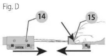
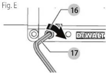
ASSEMBLY (FIG. A, D, E)
Assembling the Pole
- To assemble the pole, line up the upper trimmer pole 5 and the lower trimmer pole 6 as shown in Fig. A. Press down the latching button 15 and slide the upper pole into the lower pole. Ensure the latching button engages the latch hole 14.
- Secure the poles by tightening the middle bolt 16 with the supplied hex wrench 17 as shown in Fig. E.
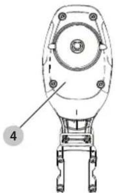
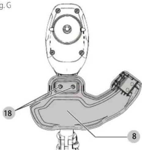
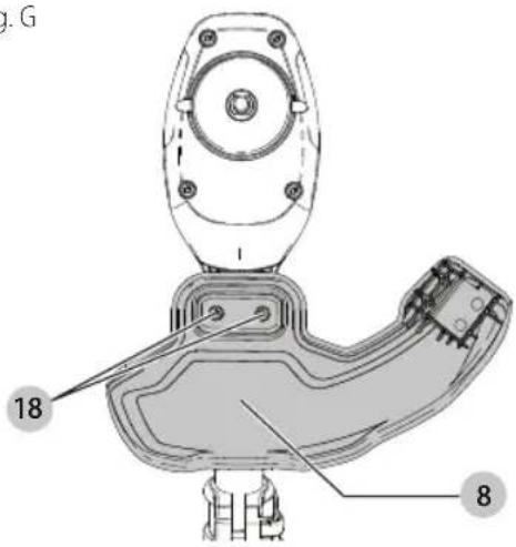
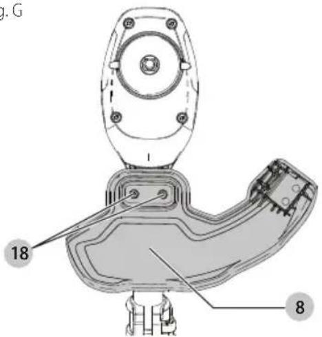
Attaching Guard (Fig. F, G)
WARNING: Never remove the guard. Damage or personal injury could result.
WARNING: NEVER OPERATE
APPLIANCE WITHOUT GUARD FIRMLY IN PLACE.
The guard must always be properly attached on the appliance to protect the user.
- Assemble the guard 8 to the motor housing 4.
- Using a cross head screwdriver, insert the 2 guard screws 18 and tighten securely.
NOTE: An extended coverage guard is available (sold separately) for extra coverage if desired. Use replacement guard Part Number N688823.
Fig. F
natural_image
Technical line drawing of a mechanical component with labeled part '4' (no text or symbols beyond label)Fig. G
ENGLISH
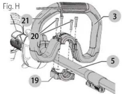
Attaching the Auxiliary Handle (Fig. A, H)
- Place the auxiliary handle 3 on top of the handle base 19 so the upper trimmer pole 5 is between them.
- Hold the auxiliary handle in place and slide the handle bolts 20 into the handle from the top, threading them into the handle base.
- Tighten the handle bolts with the supplied hex wrench 21. Ensure the handle is securely attached.
- Repeat for the other side of the auxiliary handle.
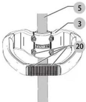
Adjustment (Fig. H, I)
WARNING: To reduce the risk of serious personal injury, turn appliance off and remove battery before making any adjustments or removing/installing attachments or accessories.
WARNING: Never remove the guard. Damage or personal injury could result.
WARNING: NEVER OPERATE APPLIANCE WITHOUT GUARD FIRMLY IN PLACE.
The guard must always be properly attached on the appliance to protect the user.
The auxiliary handle 3 is positioned to maximize balance. However, if adjustment is necessary, loosen the four bolts 20 with a hex wrench 21 and slide the auxiliary handle 3 up or down the upper trimmer pole 5.
Fig.1
OPERATION
WARNING: To reduce the risk of serious personal injury, turn appliance off and remove battery before making any adjustments or removing/installing attachments or accessories.
WARNING: Always use proper eye protection that conforms to ANSI Z87.1 (CAN/CSA Z94.3) while operating this appliance.
WARNING: Remove the battery before making any assembly, adjustments, or changing accessories. Such preventive safety measures reduce the risk of starting the TRIMMER accidentally.
CAUTION: Before you begin trimming, only use the appropriate type of cutting line.
CAUTION: Inspect area to be trimmed and remove any wire, cord, or string-like objects which could become entangled in the rotating line or spool. Be particularly careful to avoid any wire which might be bent outwardly into the path of the appliance, such as barbs at the base of a chain link fence.
Installing and Removing the Battery Pack (Fig. J, K)
WARNING: Make certain the lock-off lever is not engaged to prevent switch actuation before removing or installing battery.
NOTE: For best results, make sure your battery pack is fully charged.
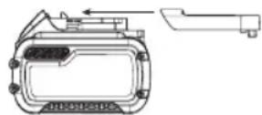
To install the battery pack: Align the battery pack 11 with the rails inside the battery housing 10 and slide it into the housing until the battery pack is firmly seated and ensure that it does not disengage.
To remove battery pack: Depress the release button 12 and firmly pull the battery pack out of the battery housing. Insert it into the charger as described in the charger section of this manual.
Fig. J
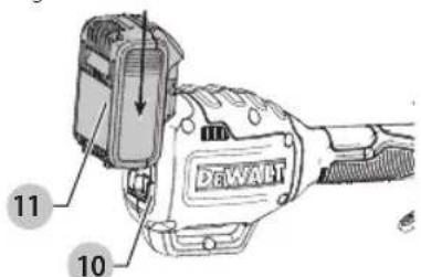
Fig. K
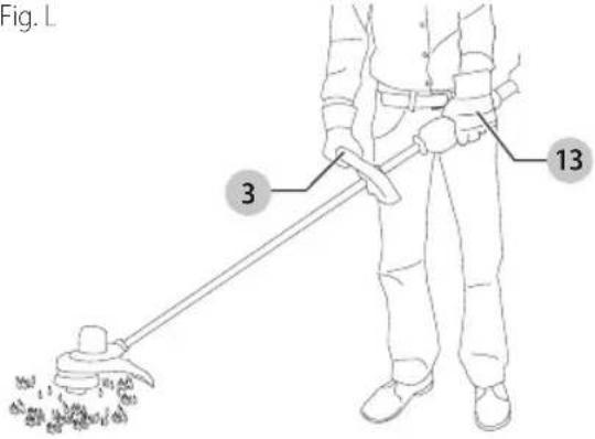
Proper Hand Position (Fig. L)
WARNING: To reduce the risk of serious personal injury, ALWAYS use proper hand position as shown.
English
WARNING: To reduce the risk of serious
personal injury, ALWAYS hold securely in anticipation of a sudden reaction.
Proper hand position requires one hand on the primary handle 3 and one hand on the auxiliary handle 13.
Fig. L
Switching Trimmer On and Off (Fig. A)
To turn the appliance on, squeeze the lock-off lever 2 and then the variable speed trigger 1. To turn the appliance off, release the variable speed trigger and the lock-off lever.
WARNING: Never attempt to lock the
trigger in the on position.
Trimming (Fig. M, N)
With the trimmer on, angle it and swing side to side as shown in Fig. M.
Maintain a minimum distance of 24" (610 mm) between the guard and your feet as shown in Fig. N.
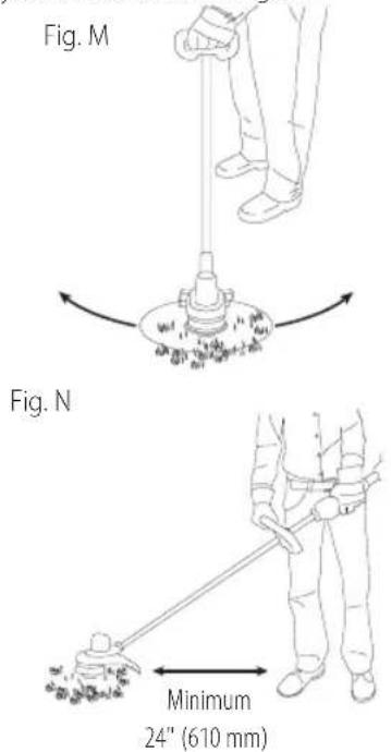
WARNING: Keep the rotating string roughly parallel with the ground (tilted no more than 30 degrees). This trimmer is not an edger. DO NOT TILT the trimmer so that the string is spinning near
a right angle to the ground. Flying debris can cause serious injury.
Bump Feed Trimmer Line Feed
Your trimmer uses 0.080" (2.0 mm) diameter nylon line. Cutting line will wear faster and require more feeding if the cutting is done along sidewalks or other abrasive surfaces or heavier weeds are being cut.
As you use the trimmer, the string will get shorter due to wear. Gently bump the trimmer on the ground while running at normal speed and the line will feed.
NOTE: Extending nylon line beyond the 13" (330 mm) swath will negatively affect performance, runtime, and the life of the trimmer due to potential of damaging motor. Doing so may void the warranty.
Helpful Cutting Tips
- Use the tip of the string to do the cutting; do not force string head into uncut grass.
- Wire and picket fences cause extra string wear, even breakage. Stone and brick walls, curbs, and wood may wear string rapidly.
- Do not allow spool cap to drag on ground or other surfaces.
- In long growth, cut from the top down and do not exceed 12" (304.8 mm) high.
- Keep trimmer tilted toward the area being cut; this is the best cutting area.
- The trimmer cuts when passing the unit from the left to right. This will avoid throwing debris at the operator.
- Avoid trees and shrubs. Tree bark, wood moldings, siding, and fence posts can easily be damaged by the string.
Replacement Accessories
WARNING: To reduce the risk of serious personal injury, turn appliance off and remove battery before making any adjustments or removing/installing attachments or accessories.
WARNING: The use of any accessory not recommended by DEWALT for use with this appliance could be hazardous.
WARNING: Do not use any blades, or any accessory or attachment other than those recommended by DEWALT on this trimmer. Serious injury or product damage may result.
Use DEWALT replacement line Model No. DWO1DT801 or DWO1DT802.
When replacing the line, use only 0.080" (2.0 mm) diameter line (Model No. DWO1DT801 or DWO1DT802 are recommended). Other sizes may degrade performance or cause damage to the trimmer.
English
Replacing the Cutting Line (Fig. A, O-R)
WARNING: To reduce the risk of serious personal injury, turn unit off and remove the battery pack. An accidental start-up can cause injury.
CAUTION: To avoid appliance damage, if the cutting line protrudes beyond the trimming blade, cut it off so that it just reaches the blade.
-
Remove battery.
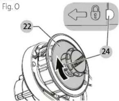
-
Turn spool 22 clockwise to unlock as shown in Fig. O. The white nub 23 (Fig. R) inside the spool will rotate away from the spool window 24 (Fig. O) to indicate it is unlocked.
-
Pull the spool straight out to remove.
-
Remove any dirt and grass from the spool and housing.
-
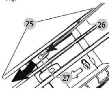
First, wind new line in the channel of the spool closest to the holding slots 25 as shown in Fig. P.
-
Place the end of the cutting line 26 into the retaining hole 27.
Fig. P
-
Wind the cutting line onto the spool in the direction of the arrow on the bottom of the spool. Make sure to wind the line on neatly and in layers. Do not crisscross.
-
When the wound cutting line reaches the beginning of the holding slots 25, cut the line approximately 4" (106 mm).
-
Push the line in the holding slots on one side of the spool to hold the first line while you wind the second line.
-
Repeat the above procedure for the second cutting line on the lower section of the spool.
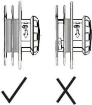
CAUTION: Before you begin trimming, only use the appropriate type of cutting line. Ensure that cutting line is present in both sections of the spool as shown in Fig. Q.
Fig. Q
-
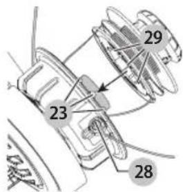
Once both lines are wrapped around the spool 22, place your thumb and finger on the holding slots to further secure the string and feed the end of each line through the two holes 28 on either side of the head in the spool housing 9 as shown in Fig. R.
-
Line up the white nubs 23 inside the spool housing with the recesses 29 of the spool. Align the holding slots 25 with the two holes 28 as close as possible.
-
Push the spool into the spool housing and turn counterclockwise to lock the spool in place. Ensure the white nub 23 appears in the spool window 24. Make sure the line doesn't unravel and wrap around the shaft below the spool.
-
Pull both ends of the cutting line to release them from the holding slots. If the line extends past the cutting blade on the guard cut the line so it just reaches the blade.
Fig. R
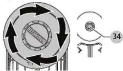
Replacing Spool Housing (Fig. A, S, T)
-
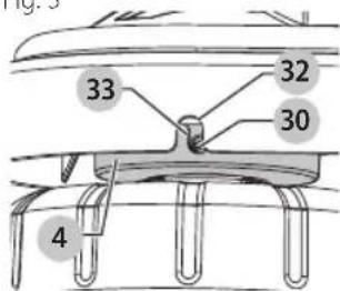
Rotate the spool housing 9 until the hole 30 in the spindle lines up with notch 32 in the guard 8. A third hole 33 in the motor housing 4 will be visible as shown in Fig. S. Insert screwdriver through each all three holes to prevent the spool housing from turning.
-
Turn the spool housing clockwise as shown in Fig. T.
-
Insert a screwdriver back through the three holes (30, 32, and 33) and thread the new spool housing counterclockwise and securely tighten onto the bolt 34 protruding from the trimmer.
Fig. S
English
Fig. T
MAINTENANCE
WARNING: To reduce the risk of serious personal injury, turn appliance off and remove battery before making any adjustments or removing/installing attachments or accessories.
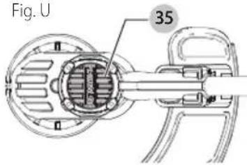
- Keep the air intake slots 35 clean to avoid overheating (Fig. U).
- Your trimmer line can dry out over time. To keep your line in top condition, store spare line in a plastic, sealable bag with a tablespoon of water.
- Plastic parts may be cleaned by using a mild soap and a damp rag.
- The line cutter on the edge of the guard can dull over time. It is recommended you periodically touch-up the sharpness of the blade with a file.
Cleaning
WARNING: Blow dirt and dust out of all air vents with clean, dry air at least once a week. To minimize the risk of eye injury, always wear ANSI Z87.1 approved eye protection when performing this.
WARNING: Never use solvents or other harsh chemicals for cleaning the non-metallic parts of the appliance. These chemicals may weaken the plastic materials used in these parts. Use a cloth dampened only with water and mild soap. Never let any liquid get inside the appliance; never immerse any part of the appliance into a liquid.
Accessories
WARNING: Since accessories, other than those offered by DEWALT have not been tested with this product, use of such accessories with this tool could be hazardous. To reduce the risk of injury, only DEWALT recommended accessories should be used with this product.
Recommended accessories for use with your tool are available at extra cost from your local dealer or authorized service center. If you need assistance in locating any accessory, please contact DEWALT, call 1-800-4-DEWALT (1-800-433-9258).
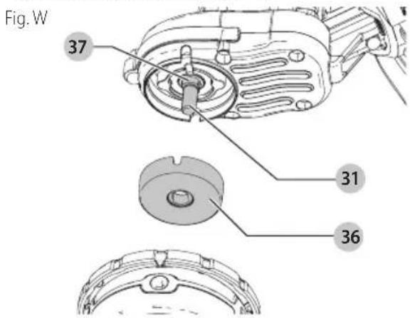
Replacing Spool Assembly (Fig. A, V, W)
- Rotate the spool housing 9 until the hole 30 in the spindle plate aligns with notch 32 in the guard. Insert a screwdriver through the notch and into the hole, to prevent the spindle from turning.
- Unscrew and remove the spool housing by turning the spool head 22 clockwise.
nOTE: Do not try to remove the spool housing by turning the spool cap 38.
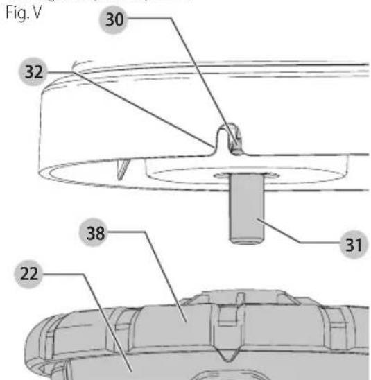
- Remove spindle plate 36 before installing a new housing. Remove any dirt and grass from the motor housing and spindle plate.
- Install spindle plate 36 onto the spindle 31, so the double D shaped retaining nut 37 on the spindle sits inside the base of the spindle plate.
- Align the spindle plate hole and notch, insert a screwdriver back into the hole and thread the new spool housing counterclockwise. Securely tighten the new spool housing onto the spindle 31.
English
Repairs
The charger and battery pack are not serviceable.
WARNING: To assure product SAFETY and RELIABILITY, repairs, maintenance and adjustment (including brush inspection and replacement, when applicable) should be performed by a DEWALT factory service center or a DEWALT authorized service center. Always use identical replacement parts.
Register Online
Thank you for your purchase. Register your product now for:
- WARRAnTY sERViCE: Registering your product will help you obtain more efficient warranty service in case there is a problem with your product.
- COnFiRMATiOn OF OWnERshiP: In case of an insurance loss, such as fire, flood or theft, your registration of ownership will serve as your proof of purchase.
- FOR YOUR SAFETY: Registering your product will allow us to contact you in the unlikely event a safety notification is required under the Federal Consumer Safety Act.
Register online at www.dewalt.com/register.
Three Year Limited Warranty
DEWALT will repair, without charge, any defects due to faulty materials or workmanship for three years from the date of purchase. This warranty does not cover part failure due to normal wear or tool abuse. For further detail of warranty coverage and warranty repair information, visit www.dewalt.com or call 1-800-4-DEWALT(1-800-433-9258). This warranty does not apply to accessories or damage caused where repairs have been made or attempted by others. THIS LIMITED WARRANTY IS GIVEN IN LIEU OF ALL OTHERS, INCLUDING THE IMPLIED WARRANTY OF MERCHANTABILITY AND FITNESS FOR A PARTICULAR PURPOSE, AND EXCLUDES ALL INCIDENTAL OR CONSEQUENTIAL DAMAGES. Some states do not allow limitations on how long an implied warranty lasts or the exclusion or limitation of incidental or consequential damages, so these limitations may not apply to you. This warranty gives you specific legal rights and you may have other rights which vary in certain states or provinces.
In addition to the warranty, DEWALTtools are covered by our:
1 YEAR FREE sERViCE
DEWALT will maintain the tool and replace worn parts caused by normal use, for free, any time during the first year after purchase.
2 YEARs FREE SERVICE On DEWAIT BATTERY PACKs
DC9096, DCB120, DCB122, DCB124, DCB127, DCB201, DCB203BT, DCB207, DCB240, DCB361
3 YEARs FREE sERViCE On DEWAIT BATTERY PACKs
DCB200, DCB203, DCB204, DCB204BT, DCB205, DCB205BT, DCB206, DCB230, DCB606, DCB609, DCB612
NOTE: Battery warranty voided if the battery pack is tampered with in any way. DEWALT is not responsible for any injury caused by tampering and may prosecute warranty fraud to the fullest extent permitted by law.
90 DAY MOnEY BACK gUARAnTEE
If you are not completely satisfied with the performance of your DEWALT Power Tool, Laser, or Nailer for any reason, you can return it within 90 days from the date of purchase with a receipt for a full refund – no questions asked.
IATin AMERiCA: This warranty does not apply to products sold in Latin America. For products sold in Latin America, see country specific warranty information contained in the packaging, call the local company or see website for warranty information.
FREE WARning IABEI REPIACEMENT: If your warning labels become illegible or are missing, call 1-800-4-DEWALT (1-800-433-9258) for a free replacement.
fabrication classe II (double isolation)
USE: 120 Wh Shipping: 3 x 40 Wh
DCB107, DCB112, DCB113, DCB115, DCB118, DCB132
*DCB107, DCB112, DCB113, DCB115, DCB118,
DCB132: le voyant rouge ne cessera de clignoter, mais
DCB107, DCB112, DCB113, DCB115, DCB118, DCB132
natural_image
Technical line drawing of a mechanical component with labeled part '4' (no text or symbols beyond label)Fig. G
FRAnÇAis
DC9096, DCB120, DCB122, DCB124, DCB127, DCB201, DCB203BT, DCB207, DCB240, DCB361
COnTRAT D'EnTRETiEn gRATUiT DE TROis Ans SUR IEs BIOC-PiIEs DEWALT
DCB200, DCB203, DCB204, DCB204BT, DCB205, DCB205BT, DCB206, DCB230, DCB606, DCB609, DCB612
USE: 120 Wh Shipping: 3 x 40 Wh
* DCB107, DCB112, DCB113, DCB115, DCB118,
DCB107, DCB112, DCB113, DCB115, DCB118, DCB132
ENSAMBLE (FIG. A, D, E)
Ensamble del poste
natural_image
Technical line drawing of a mechanical component with labeled part '4' (no text or symbols beyond label)Fig. G
Conexión de manija auxiliar (Fig. A, H)
MANTENIMIENTO
Eje Central Lázaro Cárdenas No. 18 - Local (55) 5588 9377 D, Col. Obrera
MERIDA, YUC
Calle 63 #459-A - Col. Centro (999) 928 5038
MONTERREY, N.L.
Av. Francisco I. Madero 831 Poniente - Col. (818) 375 23 13 Centro
PUEBLA, PUE
17 Norte #205 - Col. Centro (222) 246 3714
QUERETARO, QRO
Av. San Roque 274 - Col. San Gregorio (442) 2 17 63 14
SAN LUIS POTOSI, SLP
DC9096, DCB120, DCB122, DCB124, DCB127, DCB201, DCB203BT, DCB207, DCB240, DCB361
3 AÑOs DE sERViCiO gRATUiTO PARA UniDADEs DE AliMEnTACiÓn DEWAIT
DCB200, DCB203, DCB204, DCB204BT, DCB205, DCB205BT, DCB206, DCB230, DCB606, DCB609, DCB612
natural_image
Pure geometric lines forming a symmetrical shape without any text, numbers, or symbolsCompatible battery packs and chargers / Blocs-piles et chargeurs compatibles / Baterías y cargadores compatibles
| 20V Max* Li-Ion | Battery PacksBlocs-pilesBaterías | DCB200, DCB201, DCB203, DCB204, DCB204BT**, DCB205, DCB205BT**, DCB206, DCB208, DCB230, DCB240 |
| ChargersChargeursCargadores | DCB101, DCB103, DCB104, DCB107, DCB112, DCB113, DCB115, DCB118, DCB132 |
| 60V Max* Li-Ion | Battery PacksBlocs-pilesBaterías | DCB606, DCB609, DCB612 |
| ChargersChargeursCargadores | DCB101, DCB103, DCB104, DCB107, DCB112, DCB113, DCB115, DCB118, DCB132 |
* Maximum initial battery voltage (measured without a workload) is 12, 20, 60 or 120 volts. Nominal voltage is 10.8, 18, 54 or 108. (120V Max* is based on using 2 DEWALT 60V Max* lithium-ion batteries combined.)
NOTE: The Bluetooth® word mark and logos are registered trademarks owned by the Bluetooth®, SIG, Inc. and any use of such marks by DEWALTis under license. Other trademarks and trade names are those of their respective owners.
WARNING: Use of any other battery packs may create a risk of injury and fire.