DCST981B - Grass trimmer DEWALT - Free user manual and instructions
Find the device manual for free DCST981B DEWALT in PDF.

| Product Type | String Trimmer (edger) Cordless |
| Brand | DeWalt |
| Model | DCST981B |
| Power Source | 60V max Lithium-Ion Battery Pack (not included) |
| Rotation Speed | Variable by mode: ECO, Standard, Turbo |
| Cutting Width | Not specified, 0.095 in (2.4 mm) diameter line |
| Handle | Adjustable handlebar with clamping collar |
| User Protection | String trimmer guard included; extended guard available as option |
| Line Advance System | Bump feed on the ground |
| Harness | Double shoulder harness with quick release |
| Indicator Lights | Charge status LED, overload LED, speed adjustment LED |
| Speed Modes | ECO (extended runtime), Standard, Turbo (maximum power) |
| Dimensions (L x W x H) | Not specified; approximate length 1.5 m (with handlebar unfolded) |
| Weight | Approximately 3.5 to 4.5 kg with battery pack (total weight may exceed 6 kg with accessories) |
| Line Material | Spiral nylon, round and smooth edges; diameters 0.080-0.105 in (2.0-2.7 mm) |
| Intended Use | Professional lawn and garden maintenance; not a edger |
| Warranty | Two-year commercial warranty |
| Maintenance | Lubricate every 100 hours of use; clean vents regularly |
| Spare Parts | Line spool, extended guard (NA375038); use only DeWalt accessories |
| Repairability | Charger and battery pack not repairable; tool repairable by authorized DeWalt center |
| Safety | Wear PPE (safety glasses, hearing protection, gloves, closed-toe shoes); keep bystanders at 30 m |
Frequently Asked Questions - DCST981B DEWALT
User questions about DCST981B DEWALT
0 question about this device. Answer the ones you know or ask your own.
Ask a new question about this device
Download the instructions for your Grass trimmer in PDF format for free! Find your manual DCST981B - DEWALT and take your electronic device back in hand. On this page are published all the documents necessary for the use of your device. DCST981B by DEWALT.
USER MANUAL DCST981B DEWALT
WARNING: Read all safety warnings, instructions, illustrations, and specifications in this manual, including the battery and charger sections provided in an original tool manual or the separate Batteries and Chargers manual.
Manuals can be obtained by contacting Customer Service as described elsewhere in this manual. Failure to follow the warnings and instructions may result in electric shock, fire and/or serious injury.
Definitions: Safety Alert Symbols and Words
This instruction manual uses the following safety alert symbols and words to alert you to hazardous situations and your risk of personal injury or property damage.
RANGER: Indicates an imminently hazardous situation which, if not avoided, will result in death or serious injury.
WARNING: Indicates a potentially hazardous situation which, if not avoided, could result in death or serious injury.
SAUTION: Indicates a potentially hazardous situation which, if not avoided, may result in minor or moderate injury.
(Used without word) Indicates a safety related message. NOTICE: Indicates a practice not related to personal injury which, if not avoided, may result in property damage.


English (original instructions) 8
| Français (traduction de la notice d'instructions originale) | 16 |
| Español (traducido de las instrucciones originales) | 25 |
Fig. A
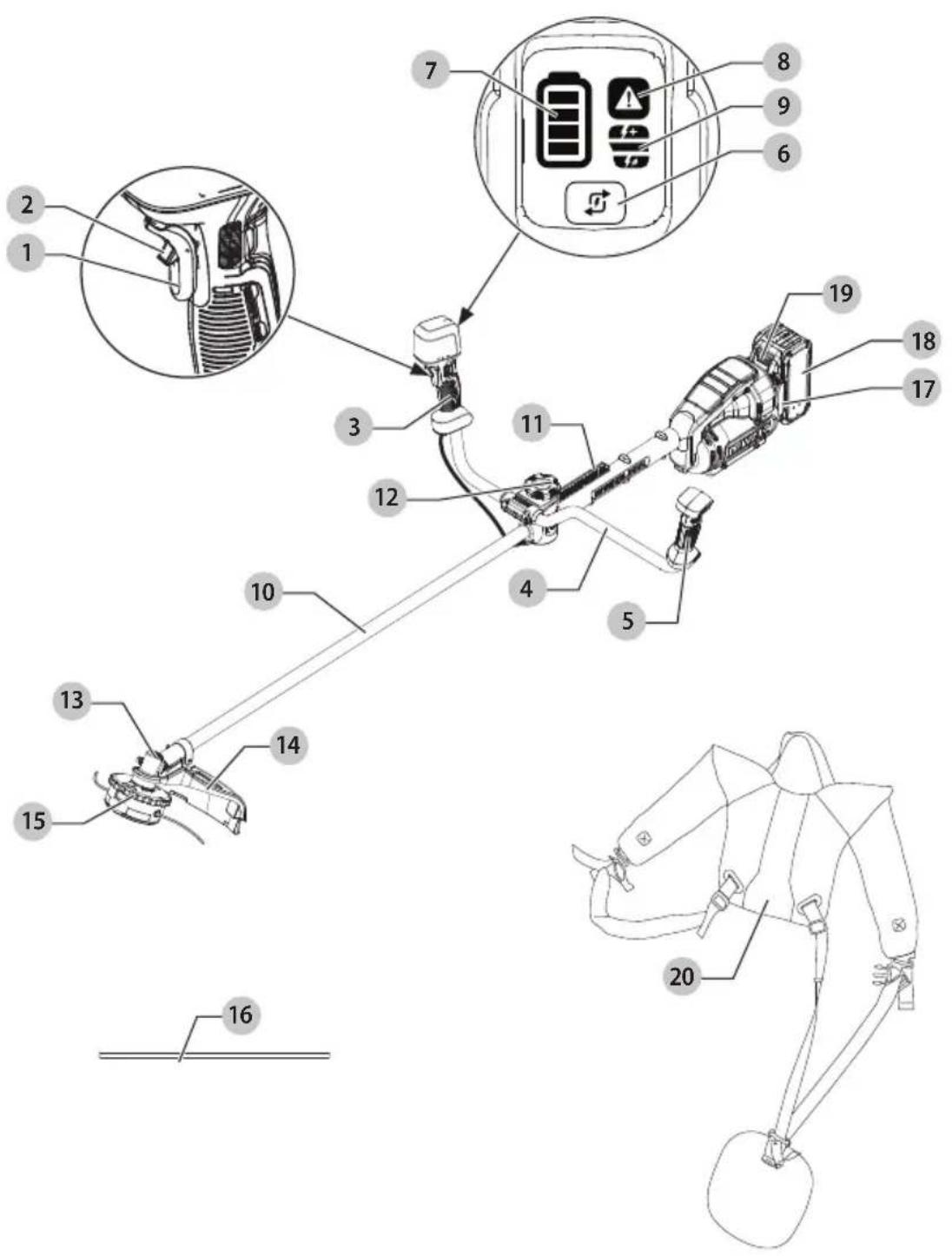
1 Variable speed trigger
2 Lock-off lever
3 Right hand grip
4 Bike handle
5 Left hand grip
6 Speed control button/Wake-up button
7 Battery state of charge LED
8 Overload indicator LED
9 Speed settings LEDs
10 Pole
11 Strap mount
12 Handle clamp screw
13 Gear case
14 String trimmer guard
15 Spool housing
16 Locking rod
17 Battery housing
18 Battery pack
19 Battery release button
20 Dual shoulder harness
Fig. E
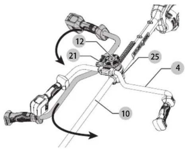
Fig. F
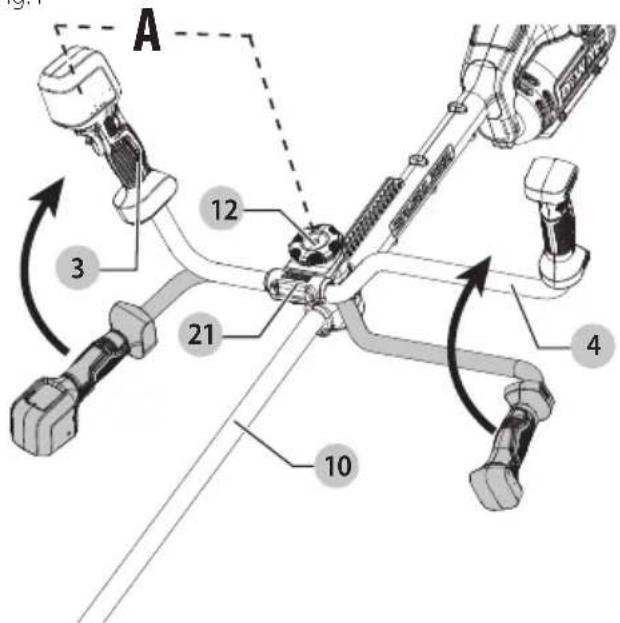
Fig. G
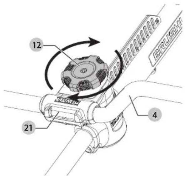
Fig. H Fig. I
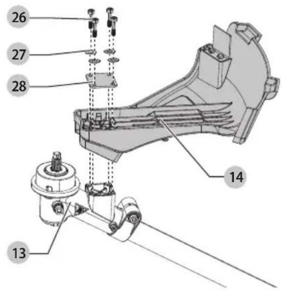
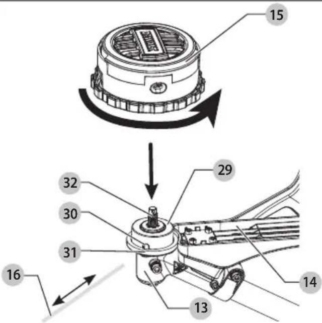
Fig. J
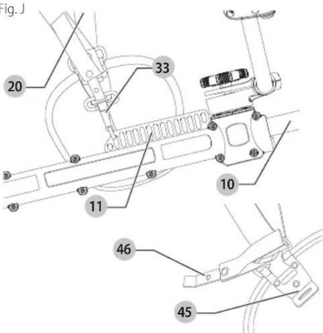
Fig. K
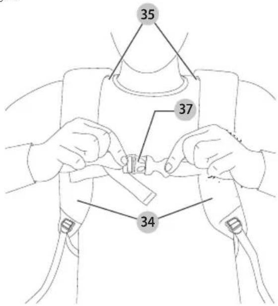
Fig. L
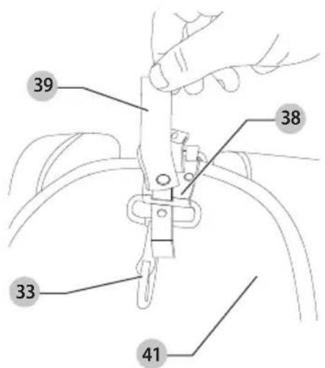
Fig. M
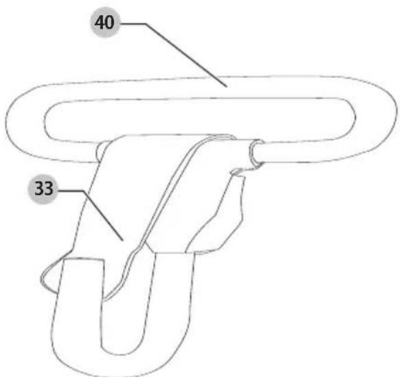
Fig. N Fig. O
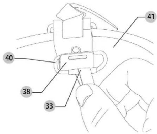
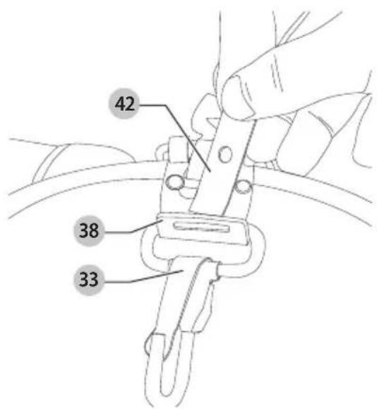
Fig. P
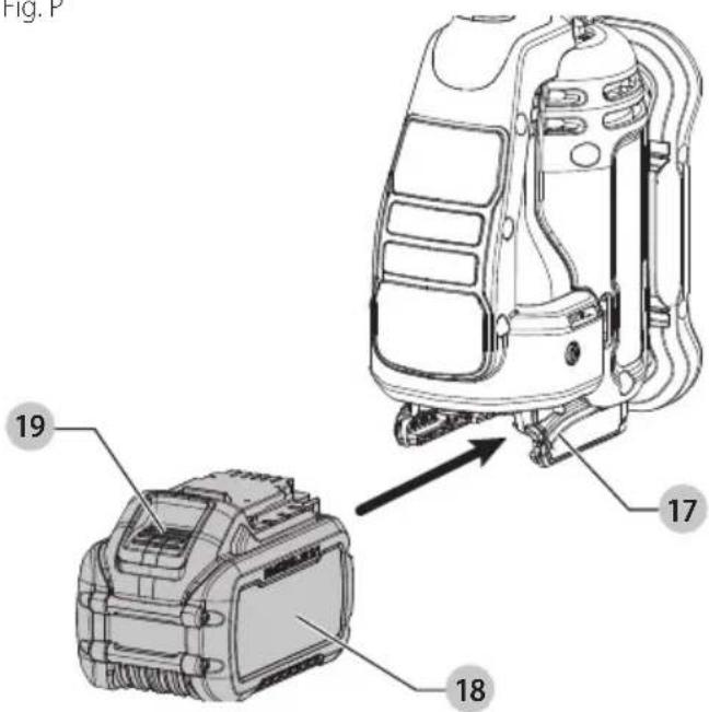
Fig. Q
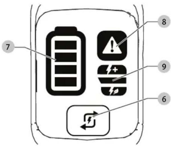
Fig. R
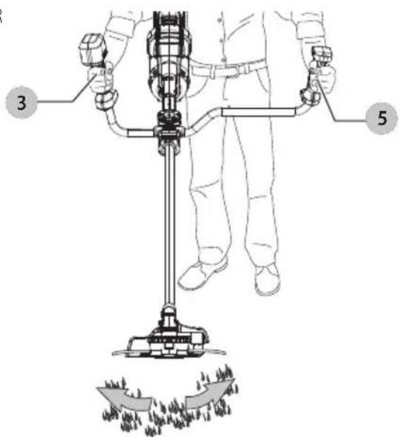
Fig. S
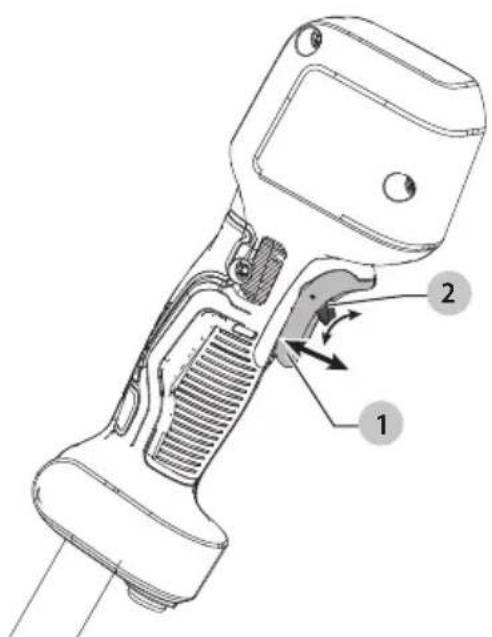
Fig. T Fig. U

natural_image
Line drawing of a person holding a device with a large 'X' symbol overlaid (no text or symbols present)Fig. V Fig. W

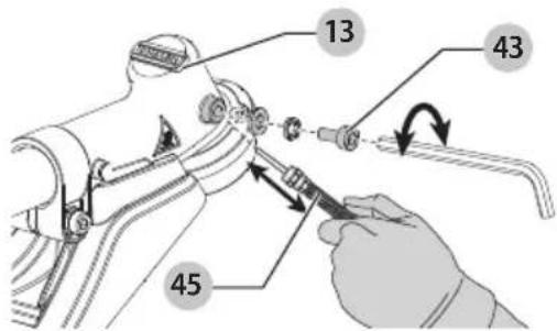
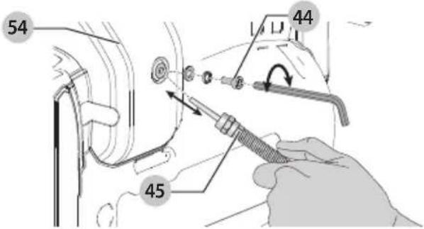
Fig. X
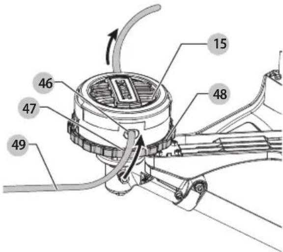
Fig. Y
English
Intended Use
The DCST981 has been designed for the purpose of professional lawn and garden maintenance. It is recommended for use with EWALT accessories This product is not an edger and is not intended to be used for edging. DO nOT use this tool for any purpose other than its intended use.
DO nOT use under wet conditions or in the presence of flammable liquids or gases.
DO nOT let children come into contact with the tool. Supervision is required when inexperienced operators use this tool.
GENERAL POWER TOOL SAFETY WARNINGS
WARNING: Read all safety warnings, instructions, illustrations and specifications provided with this power tool. Failure to follow all instructions listed below may result in electric shock, fire and/or serious injury.
SAVE ALL WARNINGS AND INSTRUCTIONS FOR FUTURE REFERENCE.
The term "power tool" in the warnings refers to your mains-operated (corded) power tool or battery-operated (cordless) power tool.
1) Work Area Safety
a) Keep work area clean and well lit. Cluttered or dark areas invite accidents.
b) Do not operate power tools in explosive atmospheres, such as in the presence of flammable liquids, gases or dust. Power tools create sparks which may ignite the dust or fumes.
c) Keep children and bystanders away while operating a power tool. Distractions can cause you to lose control.
2) Electrical Safety
a) Power tool plugs must match the outlet. Never modify the plug in any way. Do not use any adapter plugs with earthed (grounded) power tools. Unmodified plugs and matching outlets will reduce risk of electric shock. b) Avoid body contact with earthed or grounded surfaces, such as pipes, radiators, ranges and refrigerators. There is an increased risk of electric shock if your body is earthed or grounded.
c) Do not expose power tools to rain or wet conditions. Water entering a power tool will increase the risk of electric shock. d) Do not abuse the cord. Never use the cord for carrying, pulling or unplugging the power tool. Keep cord away from heat, oil, sharp edges or moving parts. Damaged or entangled cords increase the risk of electric shock.
e) When operating a power tool outdoors, use an extension cord suitable for outdoor use. Use of a cord suitable for outdoor use reduces the risk of electric shock. f) If operating a power tool in a damp location is unavoidable, use a ground fault circuit interrupter (GFCI) protected supply. Use of a GFCI reduces the risk of electric shock.
3) Personal Safety
a) Stay alert, watch what you are doing and use common sense when operating a power tool. Do not use a power tool while you are tired or under the influence of drugs, alcohol or medication. A moment of inattention while operating power tools may result in serious personal injury.
b) Use personal protective equipment. Always wear eye protection. Protective equipment such as a dust mask, non-skid safety shoes, hard hat, or hearing protection used for appropriate conditions will reduce personal injuries.
c) Prevent unintentional starting. Ensure the switch is in the off position before connecting to power source and/or battery pack, picking up or carrying the tool. Carrying power tools with your finger on the switch or energizing power tools that have the switch on invites accidents.
(19) Remove any adjusting key or wrench before turning the power tool on. A wrench or a key left attached to a rotating part of the power tool may result in personal injury.
e) Do not overreach. Keep proper footing and balance at all times. This enables better control of the power tool in unexpected situations.
f) Dress properly. Do not wear loose clothing or jewelry. Keep your hair and clothing away from moving parts. Loose clothes, jewelry or long hair can be caught in moving parts.
g) If devices are provided for the connection of dust extraction and collection facilities, ensure these are connected and properly used. Use of dust collection can reduce dust-related hazards.
h) Do not let familiarity gained from frequent use of tools allow you to become complacent and ignore tool safety principles. A careless action can cause severe injury within a fraction of a second.
4) Power Tool Use and Care
a) Do not force the power tool. Use the correct power tool for your application. The correct power tool will do the job better and safer at the rate for which it was designed.
b) Do not use the power tool if the switch does not turn it on and off. Any power tool that cannot be controlled with the switch is dangerous and must be repaired.
c) Disconnect the plug from the power source and/or remove the battery pack, if detachable, from the power tool before making any adjustments, changing accessories, or storing power tools. Such preventive safety measures reduce the risk of starting the power tool accidentally.
d) Store idle power tools out of the reach of children and do not allow persons unfamiliar with the power tool or these instructions to operate the power tool. Power tools are dangerous in the hands of untrained users.
e) Maintain power tools and accessories. Check for misalignment or binding of moving parts, breakage of parts and any other condition that may affect the power tool's operation. If damaged, have the power tool repaired before use. Many accidents are caused by poorly maintained power tools.
f) Keep cutting tools sharp and clean. Properly maintained cutting tools with sharp cutting edges are less likely to bind and are easier to control.
g) Use the power tool, accessories and tool bits, etc. in accordance with these instructions, taking into account the working conditions and the work to be performed. Use of the power tool for operations different from those intended could result in a hazardous situation.
h) Keep handles and grasping surfaces dry, clean and free from oil and grease. Slippery handles and grasping
surfaces do not allow for safe handling and control of the tool in unexpected situations.
5) Battery Tool Use and Care
a) Recharge only with the charger specified by the manufacturer. A charger that is suitable for one type of battery pack may create a risk of fire when used with another battery pack.
b) Use power tools only with specifically designated battery packs. Use of any other battery packs may create a risk of injury and fire.
c) When battery pack is not in use, keep it away from other metal objects, like paper clips, coins, keys, nails, screws or other small metal objects, that can make a connection from one terminal to another. Shorting the battery terminals together may cause burns or a fire.
d) Under abusive conditions, liquid may be ejected from the battery; avoid contact. If contact accidentally occurs, flush with water. If liquid contacts eyes, additionally seek medical help. Liquid ejected from the battery may cause irritation or burns.
e) Do not use a battery pack or tool that is damaged or modified. Damaged or modified batteries may exhibit unpredictable behavior resulting in fire, explosion or risk of injury.
f) Do not expose a battery pack or tool to fire or excessive temperature. Exposure to fire or temperature above 265 °F (130 °C) may cause explosion.
g) Follow all charging instructions and do not charge the battery pack or tool outside the temperature range specified in the instructions. Charging improperly or at temperatures outside the specified range may damage the battery and increase the risk of fire.
6) Service
a) Have your power tool serviced by a qualified repair person using only identical replacement parts. This will ensure that the safety of the power tool is maintained.
b) Never service damaged battery packs. Service of battery packs should only be performed by the manufacturer or authorized service providers.
Grass Trimmer, Brush Cutter and Brush Saw Safety Warnings
a) Do not use the machine in bad weather conditions, especially when there is a risk of lightning. This decreases the risk of being struck by lightning.
b) Thoroughly inspect the area for wildlife where the machine is to be used. Wildlife may be injured by the machine during operation.
c) Thoroughly inspect the area where the machine is to be used and remove all stones, sticks, wires, bones, and other foreign objects. Thrown objects can cause personal injury.
d) Before using the machine, always visually inspect to see that the cutter or blade and the cutter or blade assembly are not damaged. Damaged parts increase the risk of injury.
e) Follow instructions for changing accessories.
Improperly tightened blade securing nuts or bolts may either damage the blade or result in it becoming detached.
f) The rated rotational speed of the blade must be at least equal to the maximum rotational speed marked on the machine. Blades running faster than their rated rotational speed can break and fly apart.
g) Wear eye, ear, head and hand protection. Adequate protective equipment will reduce personal injury by flying debris or accidental contact with the cutting line or blade.
h) While operating the machine, always wear non-slip and protective footwear. Do not operate the machine when barefoot or wearing open sandals. This reduces the chance of injury to the feet from contact with the moving cutters or lines.
i) While operating the machine, always wear safety footwear. Do not operate the machine when barefoot or wearing open sandals. This reduces the chance of injury to the feet from contact with a moving cutter, line or blade.
j) While operating the machine, always wear long trousers. Exposed skin increases the likelihood of injury from thrown objects.
k) Keep bystanders away while operating the machine. Thrown debris can result in serious personal injury.
1) Always use two hands when operating the machine. Holding the machine with both hands will avoid loss of control.
m) Hold the machine by the insulated gripping surfaces only, because the cutting line or blade may contact hidden wiring. Cutting line or blades contacting a "live" wire may make exposed metal parts of the machine "live" and could give the operator an electric shock.
n) Always keep proper footing and operate the machine only when standing on the ground. Slippery or unstable surfaces may cause a loss of balance or control of the machine.
o) Do not operate the machine on excessively steep slopes. This reduces the risk of loss of control, slipping and falling which may result in personal injury.
p) When working on slopes, always be sure of your footing, always work across the face of slopes, never up or down and exercise extreme caution when changing direction. This reduces the risk of loss of control, slipping and falling which may result in personal injury.
q) Keep all parts of the body away from the cutter, line or blade when the machine is operating. Before you start the machine, make sure the cutter, line or blade is not contacting anything. A moment of inattention while operating the machine may result in injury to yourself or others.
r) Do not operate the machine above waist height. This helps prevent unintended cutter or blade contact and enables better control of the machine in unexpected situations.
s) When cutting brush or saplings that are under tension, be alert for spring back. When the tension in the wood fibres is released, the brush or sapling may strike the operator and/or throw the machine out of control.
t) Use extreme caution when cutting brush and saplings. The slender material may catch the blade and be whipped toward you or pull you off balance.
u) Maintain control of the machine and do not touch cutters, lines or blades and other hazardous moving parts while they are still in motion. This reduces the risk of injury from moving parts.
v) Carry the machine with the machine switched off and away from your body. Proper handling of the machine will reduce the likelihood of accidental contact with a moving cutter, line or blade.
w) When transporting or storing the machine, always fit the cover on metal blades. Proper handling of the machine will reduce the likelihood of accidental contact with the blade.
x) Only use replacement cutters, lines, cutting heads and blades specified by the manufacturer. Incorrect replacement parts may increase the risk of breakage and injury.
y) When clearing jammed material or servicing the machine, make sure the switch is off and the battery
ENGLISH
pack is removed. Unexpected starting of the machine while clearing jammed material or servicing may result in serious personal injury.
Additional Safety Information
a) Always use the shoulder harness when operating.
b) Do not use for edging. This is not an edger.
c) KEEP ALL BYSTANDERS AWAY – at a safe distance from work area, especially children. MAKE SURE that other persons and pets are at least 100' (30 m) away.
WARNING: Never modify the power tool or any part of it. Damage or personal injury could result.
WARNING: Do not modify or attempt to repair the appliance or the battery pack except as indicated in the instructions for use and care.
WARNING: ALWAYS use safety glasses. Everyday eyeglasses are NOT safety glasses. Also use face or dust mask if operation is dusty. ALWAYS WEAR CERTIFIED SAFETY EQUIPMENT:
• ANSI Z87.1 eye protection (CAN/CSA Z94.3),
• ANSI S12.6 (S3.19) hearing protection,
• NIOSH/OSHA/MSHA respiratory protection.
WARNING: Some dust contains chemicals known to State of California to cause cancer, birth defects or other reproductive harm. Some examples of these chemicals are:
• compounds in fertilizers,
• compounds in insecticides, herbicides and pesticides,
• arsenic and chromium from chemically treated lumber.
To reduce your exposure to these chemicals, wear approved safety equipment such as dust masks that are specially designed to filter out microscopic particles.
- Avoid prolonged contact with dust from power sanding, sawing, grinding, drilling, and other construction activities. Wear protective clothing and wash exposed areas with soap and water. Allowing dust to get into your mouth, eyes, or lie on the skin may promote absorption of harmful chemicals.
WARNING: Use of this tool can generate and/or disperse dust, which may cause serious and permanent respiratory or other injury. Always use NIOSH/OSHA approved respiratory protection.
WARNING: Always wear proper personal hearing protection that conforms to ANSI S12.6 (S3.19) during use. Under some conditions and duration of use, noise from this product may contribute to hearing loss.
NAUTION: When not in use, place tool on its side on a stable surface where it will not cause a tripping or falling hazard. Some tools with a large battery pack will stand upright but may be easily knocked over.
• Air vents often cover moving parts and should be avoided. Loose clothes, jewelry or long hair can be caught in moving parts.
The label on your tool may include the following symbols. The symbols and their definitions are as follows:
V....volts
Hz hertz
min......minutes
or DC.....direct current
Class I Construction
(grounded)
.../min.....per minute
BPM.....beats per minute
or AC/DC....alternating or direct current
Class II Construction (double insulated)
n_0 .....no load speed n .....rated speed
PSI..... pounds per square inch
⊕ ....earthing terminal
⚠️ ......safety alert symbol
▲......visible radiation—do not stare into the light
wearrespiratory protection
⑦ wear eye protection
wearhand protection
L .... wear slip resistant footwear
......wearhead protection
© ....wearhearing protection
read user manual
do not expose to rain
do not use flexible line
do not use metal blades
bewareof thrown objects
the distance between the machine and bystanders shall be at least 100 ft (30 m)
......bewareof blade thrust
disconnectbattery before maintenance
ASSEMBLY AND ADJUSTMENTS
WARNING: To reduce the risk of serious personal injury, turn unit off and remove the battery pack before making any adjustments or removing/installing attachments or accessories. An accidental start-up can cause injury.
Mounting the Bike Handle (Fig. B–G)
- Unthread the handle clamp screw 12 by turning it counterclockwise until the handle clamp 21 can be removed from the handle mount 25 as shown in Fig. B.
NOTE: Do not lose the clamp screw spring 22. - Place the bike handle 4 on top of the lower handle clamp 23 and then place the upper handle clamp 24 on top of the bike handle 4 and into the lower handle clamp 23 as shown in Fig. C.
- Place the handle clamp screw 12 through the handle clamp assembly. With one hand holding the handle clamp assembly, use your other hand to guide the clamp screw spring 22 onto the handle clamp screw 12. Place the handle clamp screw 12 into the handle mount 25 on the pole 10.
NOTE: Ensure the clamp screw spring 22 is in place before securing the handle clamp assembly. - Loosely tighten the handle clamp screw 12 by turning it clockwise until the handle clamp 21 can still be moved on the handle mount 25 as shown in Fig. D. Do not fully tighten the handle clamp screw 12 at this point.
- Rotate the bike handle 4 up to its working position as shown in Fig. E and F. Adjust it so that the distance "A" is roughly 7" (17 cm) as shown in Fig. F.
- Fully tighten the handle clamp screw 12. Ensure that the handle is secured in position before operating the unit as shown in Fig. G.
Folding the Bike Handle (Fig. D–G)
Folding:
- Unthread the handle clamp screw 12 by turning it counterclockwise until the handle clamp 21 can be rotated counterclockwise.
NOTE: Do not fully loosen the clamp screw 12.
- Rotate the bike handle 4 counterclockwise and down to its storage position inline with the pole 10.
- Tighten the handle clamp screw 12 by turning it clockwise until snug.
Unfolding:
- Unthread the handle clamp screw 12 by turning it counterclockwise until the handle clamp 21 can be rotated clockwise.
- Rotate the bike handle 4 clockwise and up to its working position and adjust it so that the distance "A" is roughly 7" (17 cm) as shown in Fig. F.
- Fully tighten the handle clamp screw 12. Ensure that the handle is secured in position before operating the unit.
Assembling the Guard (Fig. H)
WARNING: NEVER OPERATE appliance WITHOUT GUARD FIRMLY IN PLACE. The guard must always be properly attached on the appliance to protect the user.
- Place the string trimmer guard 14 into position as shown in Fig. H.
- Use a 3 mm hex wrench (not included) to secure it to the gear case 13 with the four guard screws 26, washers 27 and plate 28 and tighten it securely.
Installing the Spool Assembly (Fig. I)
- Remove the battery.
- Ensure the string trimmer guard 14 is installed before proceeding.
- Install the spindle plate 29 onto the shaft 32, so the notch is facing towards the gear case.
- Align the spindle plate hole 30 with the notch 31, insert the locking rod 16 or screwdriver back into the hole 30 and thread the new spool housing counterclockwise. Securely tighten the new spool housing onto the shaft 32.
- Thread the spool housing 15 counterclockwise onto the shaft 32. Securely tighten the spool housing 15.
Installing and Removing the Shoulder Harness (Fig. J, K)
WARNING: The shoulder straps should be slung over both shoulders and not across the body. See Fig. K. The shoulder harness 20 will fit sizes XS–XXL.
A dual shoulder harness 20 is recommended for any tool with a total weight exceeding 13 lbs. (6 kg). (Total weight includes the tool, attachment, and battery.) Attach the dual shoulder harness to the tool as shown in Fig. J and adjust for proper balance and support
- Grab the dual shoulder harness 20 and slide your arms through each one of the shoulder straps 34 ensuring each one hangs on your shoulders 35 as shown in Fig. K.
- Buckle the chest strap 37.
- Snap the shoulder strap latch 33 onto the strap mount 11 located on the pole 10, just in front of the motor housing as shown in Fig. J.
- Tighten the shoulder straps 34 and chest strap 37 until they fit securely against your body and over your shoulders 35 to provide proper balance and support of the tool.
- To remove the dual shoulder harness 20, unbuckle the chest strap 37. Loosen the shoulder straps 34. Pull your arms through each one of the shoulder straps 34.
Shoulder Harness Quick Release (Fig. J, L-O)
The dual shoulder harness 20 is equipped with a quick release mechanism 38. To quickly release the tool from the user without removing the dual shoulder harness, pull the quick release strap 39 as shown in Fig. L.
- To reattach the dual shoulder harness to the tool after pulling the quick release strap 39, remove the shoulder strap latch 33 as shown in Fig. M, from the strap mount 11.
- Slide the strap latch loop 40 onto the quick release mechanism 38 as shown in Fig. N.
- Slide the quick release fitting 42 through the quick release mechanism 38 as shown in Fig. O.
- Attach the shoulder strap latch 33 to the strap mount 11 as shown in Fig. J.
OPERATION
WARNING: To reduce the risk of serious personal injury, turn unit off and remove the battery pack before making any adjustments or removing/installing attachments or accessories. An accidental start-up can cause injury.
Installing and Removing the Battery Pack (Fig. P)
WARNING: Ensure the tool/appliance is in the off position before inserting the battery pack.
NOTE: For best results, make sure your battery pack is fully charged.
- To install the battery pack 18 into the tool handle, align the battery pack with the rails inside the tool's handle and slide it into the handle until the battery pack is firmly seated in the tool and ensure that it does not disengage.
- To remove the battery pack from the tool, press the battery pack release button 19 and firmly pull the battery pack out of the tool handle.
State of Charge Indicator (Fig. A, Q)
The DCST981 is equipped with a state of charge indicator. This will display the current level of charge in the battery during use. It does not indicate tool functionality and is subject to variation based on product components, temperature and end-user application.
- The state of charge indicator LEDs 7 will illuminate, indicating the percent of charge in the battery.
- When all four state of charge indicator LEDs 7 illuminate, the battery is fully charged.
- When one state of charge indicator LEDs 7 illuminates, charge is low and then it will flash when the battery is discharged. Remove the battery and charge it.
State of Charge Indicator LED Status
| LEVEL OF CHARGE | CHARGE INDICATORLED COLOR | |
| 100% - 75% White | ||
| 50% - 75% White | ||
| 20% - 50% White | ||
| ≤20% White |
LEVEL OF CHARGE
CHARGE INDICATOR LED COLOR

Low battery shutdown White and blinking.

Battery too hot All four, red and blinking.
Overloaded Battery Warning (Fig. A, Q)
All four state of charge indicator LEDs 7 will illuminate red and then blink when the battery has reached a high temperature. To clear the overloaded battery warning, allow the battery to cool down then restart the trimmer and begin cutting again, this time with less force. Allow the trimmer to cut at its own pace.
Overload LED (Fig. A, Q)
The DCST981 has an overload LED 8. The overload LED 8 will illuminate amber and then blink when the motor or module is overloaded during operation. To clear the overload LED 8, restart the trimmer and begin cutting again, this time with less force. Allow the trimmer to cut at its own pace.
The overload LED 8 will illuminate red and then blink when the module has reached a high temperature. To clear the overload LED 8, allow the trimmer to cool down then restart the trimmer and begin cutting again, this time with less force. Allow the trimmer to cut at its own pace.
Proper Hand Position (Fig. R)
WARNING: To reduce the risk of serious personal injury, ALWAYS use proper hand position as shown.
WARNING: To reduce the risk of serious personal injury, ALWAYS hold securely in anticipation of a sudden reaction.
WARNING: Hold the tool using only the two handle grips.
WARNING: Do not use the pole as a gripping surface.
Proper hand position requires one hand on the right hand grip 3 and one hand on the left hand grip 5 of the bike handle 4.
Switching On (Fig. A, Q–S)
WARNING: Grip tool firmly when switching on.
AUTION: Always wear safety glasses and hearing protection. Wear a filter mask if the operation is dusty. Always wear gloves, long pants and substantial closed toe footwear. Keep long hair and loose clothing away from openings and moving parts.
- The speed control button/wake-up button 6 must be pressed before use to wake up the appliance.
NOTE: The appliance will enter sleep mode after sixty seconds of inactivity. The appliance can also be forced into sleep mode by pressing and holding the speed control button/wake-up button 6 for two seconds.
-
To turn the appliance on, push the lock-off tab 2 forward, squeeze the lock-off lever 2 and then the variable speed trigger switch 1.
-
To turn the appliance off, release the variable speed trigger switch and lock-off lever.
WARNING: Never attempt to lock the trigger switch in the on position.
Adjusting Motor Speed (Fig. Q)
The DCST981 is equipped with a speed indicator 9. The speed indicator 9 will display the chosen speed. There are three speed setting LEDs, ECO mode 51, standard mode 52 and turbo mode 53. The speed indicator 9 helps you to optimize the appliance's performance and runtime needed for each job.
- The speed control button/wake-up button 6 must be pressed before use to wake up the appliance.
NOTE: The tool defaults to ECO mode 51.
- Press the speed control button/wake-up button 6, located on the appliance handle, until the desired speed LED is illuminated.
NOTE: Operate in ECO mode 51 or standard mode 52 for larger projects that require more runtime to complete.
- Choose turbo mode 53 as needed to cut through heavier growth and for applications that need higher RPM. nOTE: Runtime will be reduced.
Speed Setting LED Colors
SPEED SPEED SETTING LED COLOR


Trimming (Fig. R, T–V)
With the string trimmer on, angle it and swing side to side as shown in Fig. R.
Maintain a minimum distance of 24" (610 mm) between the guard 14 and your feet as shown in Fig. V.
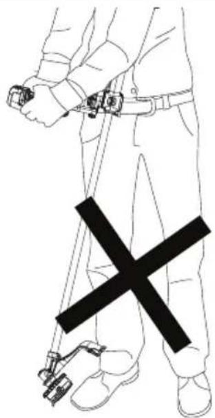
WARNING: Keep the rotating string roughly parallel with the ground (tilted no more than 30°). This trimmer is not an edger. DO NOT TILT the trimmer so that the string is spinning near a right angle to the ground. Flying debris can cause serious injury as shown in Fig. U.
Bump Feed Trimmer Line Feed (Fig. X, Y)
Your trimmer comes with 0.095" (2.4 mm) but can also use 0.080" (2.0 mm) or 0.105" (2.7 mm) diameter nylon line. Cutting line 49 will wear faster and require more feeding if the cutting is done along sidewalks or other abrasive surfaces or heavier weeds are being cut.
As you use the trimmer, the string will get shorter due to wear. Gently bump the trimmer on the ground while running at normal speed and the cutting line 49 will feed.
NOTE: Extending the cutting line 49 beyond the cutting line blade 50 will negatively effect performance, runtime, and the life of the trimmer due to potential of damaging motor. Doing so may void the warranty.
Helpful Trimming Tips
- Use the tip of the string to do the cutting; do not force string head into uncut grass.
- Wire and picket fences cause extra string wear, even breakage. Stone and brick walls, curbs, and wood may wear string rapidly.
- Do not allow spool cap to drag on ground or other surfaces.
- In long growth, cut from the top down and do not exceed 12" (300 mm) high.
- Keep trimmer tilted toward the area being cut; this is the best cutting area.
- The trimmer spins counterclockwise when viewed from behind and above. Cutting from right to left will throw debris toward the guard and catch the trimmings. It is recommended to cut from right to left when near gardens or flower beds as this will help to keep trimmings from being thrown into those areas. Cutting from left to right will throw debris away from the guard. Use this method when debris location is not important.
- Avoid trees and shrubs. Tree bark, wood moldings, siding, and fence posts can easily be damaged by the string.
MAINTENANCE
WARNING: To reduce the risk of serious personal injury, turn unit off and remove the battery pack before making any adjustments or removing/installing attachments or accessories. An accidental start-up can cause injury.
Your DEWÄLT power tool has been designed to operate over a long period of time with a minimum of maintenance. Continuous satisfactory operation depends upon proper tool care and regular cleaning.
Applying Grease (Fig. W)
The DCST981 needs to be greased after every 100 hours of use.
- Using a 5 mm hex wrench (not included), remove the grease port screw 43 and motor grease port screw 44.
- Apply a small amount (3-5 grams) of DEWALT 30301914 grease 45 into the ports as shown in Fig. W.
- Reinstall the port screws 43 and 44, using a 5 mm hex wrench (not supplied) to tighten the screws.
Cleaning
WARNING: Blow dirt and dust out of all air vents with clean, dry air at least once a week. To minimize the risk of eye injury, always wear ANSI Z87.1 approved eye protection when performing this procedure.
WARNING: Never use solvents or other harsh chemicals for cleaning the non-metallic parts of the tool. These chemicals may weaken the plastic materials used in these parts. Use a cloth dampened only with water and mild soap. Never let any liquid get inside the tool; never immerse any part of the tool into a liquid.
Accessories
WARNING: Since accessories, other than those offered by DEWALT, have not been tested with this product, use of such accessories with this product could be hazardous. To reduce the risk of injury, only DEWALT-recommended accessories should be used with this product.
Recommended accessories for use with your product are available at extra cost from your local dealer or authorized service center. If you need assistance in locating any accessory, please contact DEWALT. Call 1-800-4-DEWALT (1-800-433-9258) or visit our website: www.dewalt.com.
WARNING: The use of any accessory not recommended by DEWALT for use with this appliance could be hazardous.
WARNING: Do not use any blades, or any accessory or attachment other than those recommended by DEWALT on this trimmer. Serious injury or product damage may result.
Reloading the Cutting Line (Fig. X, Y)
AUTION: Use only DEWALT replacement spools and line. Using any other manufacturer's line can reduce performance, damage the trimmer or cause personal injury. Your trimmer comes with 0.095" (2.4 mm) but can also use 0.080" (2.0 mm) or 0.105" (2.7 mm) diameter nylon line that is spiral-shaped with smooth round edges. Do not use other size lines. This can degrade performance, cause damage to the unit or injury.
CAUTION: To avoid appliance damage, if the cutting line protrudes beyond the trimming blade, cut it off so that it just reaches the blade.
Use only DEWALT replacement line. Do not use wire.
-
Remove battery.
-
Cut a maximum length of 20 ft (6 m) of 0.105", 30 ft (9 m) of 0.095" and 40 ft (12 m) of 0.080" cutting line.
-
Align the spool housing eyelets 46 with the arrow 47 on the spool grip cover 48 as shown in Fig. X.
-
Thread one end of the trimmer line through an eyelet.
-
Guide the line through to the second eyelet and continue to pull the line through until there are equal lengths of string on each side of the spool housing.
-
Secure the spool cap from moving with one hand. Using your other hand, wind the string onto the spool by rotating the spool grip cover counterclockwise.
-
Continue winding until 5" (130 mm) of string remain on each side of the spool housing as shown in Fig. Y.
Replacing Spool Assembly (Fig. Z)
- Remove the battery.
- Rotate the spool housing 15 until the hole 30 in the spindle plate aligns with notch 31 in the gear case. Insert the locking rod 16 or a screwdriver through the notch and into the hole, to prevent the spindle from turning.
- Unscrew and remove the spool housing by turning the spool grip cover 48 clockwise.
NOTE: Do not try to remove the spool housing by turning the spool housing 15. - Remove spindle plate 29 before installing a new spool. Remove any dirt and grass from the gear case and spindle plate.
- Install spindle plate 29 onto the shaft 32, so the notch is facing towards the gear case 13.
- Align the spindle plate hole 30 and notch 31, insert the locking rod 16 or screwdriver back into the hole 30 and thread the new spool housing counterclockwise. Securely tighten the new spool housing onto the shaft 32.
ENGLISH
Replacing Guard With Extended Coverage Guard (Fig. AA)
An extended coverage guard is available (sold separately) for extra coverage if desired. Use DEWALT replacement guard Part Number NA375038.
WARNING: Never operate appliance without guard firmly in place.
- Remove the spool housing as described in the Replacing Spool Assembly section.
- Use a 3 mm hex wrench (not included) to remove the four guard screws 26 shown in Fig. AA.
- Lift the guard off.
- Attach the extended coverage guard 36 to the gear case 13 with the four guard screws 26, washers 27 and plate 28 and then tighten the screws to secure in position as shown in Fig. AA.
- Replace the spool housing as described in the Replacing Spool Assembly section.
Repairs
The charger and batteries are not serviceable. There are no serviceable parts inside the charger or battery pack.
WARNING: To assure product SAFETY and RELIABILITY, repairs, maintenance and adjustment (including brush inspection and replacement, when applicable) should be performed by a factory service center or an authorized service center. Always use identical replacement parts.
Register Online
Thank you for your purchase. Register your product now for:
- WARRANTY SERVICE: Registering your product will help you obtain more efficient warranty service in case there is a problem with your product.
- CONFIRMATION OF OWNERSHIP: In case of an insurance loss, such as fire, flood or theft, your registration of ownership will serve as your proof of purchase.
• FOR YOUR SAFETY: Registering your product will allow us to contact you in the unlikely event a safety notification is required under the Federal Consumer Safety Act.
Register online at www.dewalt.com/account-login.
Two Year Commercial Warranty
For warranty terms, go to https://www.dewalt.com/support/warranty.
To request a written copy of the warranty terms, contact: Customer Service at DEWALT Industrial Tool Co., 701 East Joppa Road, Towson, MD 21286 or call 1-800-4-DEWALT (1-800-433-9258).
LATIN AMERICA: This warranty does not apply to products sold in Latin America. For products sold in Latin America, see country-specific warranty information contained in the packaging, call the local company or see website for warranty information.
FREE WARNING LABEL REPLACEMENT: If your warning labels become illegible or are missing, call 1-800-4-DEWALT (1-800-433-9258) for a free replacement.
TROUBLESHOOTING
Problem Solution
| Unit will not start. Check battery installation. | |
| Check battery charging requirements. | |
| Press the On/Off button before squeezing the lock off lever and trigger switch. | |
| Check that lock off lever is fully pushed forward prior to moving trigger switch. | |
| Unit shuts down in use. | Charge battery. |
| Unit is being forced. Restart and apply less pressure. | |
LED Indicator Guide
The section provides a list of possible LED blink patterns, the causes and corrective solutions. The user or maintenance personnel can perform some corrective actions, while others may require the assistance of a qualified DEWALT technician or your dealer.
Overload LED

ORANGE LED
Problem Solution
| Unit stopped working. | Unit is being forced. Restart and apply less pressure. If problem continues, contact DEWALT customer service representative at 1-800-4-DEWALT (1-800-433-9258). |

RED LED
Problem Solution
| Unit module is too hot. | Unit is being forced. Let the unit rest and cool down. Restart and apply less pressure.If problem continues, contact DEWALT customer service representative at 1-800-4-DEWALT (1-800-433-9258). |
State of Charge Indicator LEDs

BLINKING WHITE LEDs
Problem Solution
| Battery pack is depleted. | Remove and replace the battery pack. If problem continues, contact DEWALT customer service representative at 1-800-4-DEWALT (1-800-433-9258). |

BLINKING RED LEDs
Problem Solution
| Battery is too hot. Unit is being forced. Let the unit rest and cool down. Restart and apply less pressure.Remove and replace the battery pack. Restart and apply less pressure.If problem continues, contact DEWALT customer service representative at 1-800-4-DeWALT (1-800-433-9258). |
FRAnÇAis
Utilisation Prévue
--- o DC.....corriente directa
Eje Central Lázaro Cárdenas No. 18 - Local (55) 5588 9377 D, Col. Obrera
MERIDA, YUC
Calle 63 #459-A - Col. Centro (999) 928 5038
MONTERREY, N.L.
Av. Francisco I. Madero 831 Poniente - Col. (818) 375 23 13 Centro
PUEBLA, PUE
17 Norte #205 - Col. Centro (222) 246 3714
QUERETARO, QRO
Av. San Roque 274 - Col. San Gregorio (442) 2 17 63 14
SAN LUIS POTOSI, SLP
Col. Santa Fe Alvaro Obregon,
Ciudad de Mexico, Mexico.
C.P 01210
TEL(52) 55 53267100
R.F.C.BDE8106261W7
Registro en Línea
WARNING: Use of any other battery packs may create a risk of injury and fire.
NOTE: DO NOT charge when the battery pack is below 40 °F ( 4.5 °C ) or above 104 °F ( 40 °C ). Do not store or use the tool and battery pack in locations where the temperature may reach or exceed 104 °F ( 40 °C ).
PART NUMBER