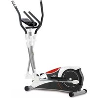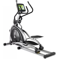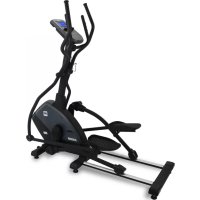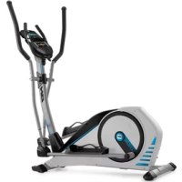
Azzure TFT G2362TFT - Elliptical bike BH FITNESS - Free user manual and instructions
Find the device manual for free Azzure TFT G2362TFT BH FITNESS in PDF.


User questions about Azzure TFT G2362TFT BH FITNESS
0 question about this device. Answer the ones you know or ask your own.
Ask a new question about this device
Download the instructions for your Elliptical bike in PDF format for free! Find your manual Azzure TFT G2362TFT - BH FITNESS and take your electronic device back in hand. On this page are published all the documents necessary for the use of your device. Azzure TFT G2362TFT by BH FITNESS.
USER MANUAL Azzure TFT G2362TFT BH FITNESS
natural_image
Line drawing of a stationary exercise bike with adjustable arms and wheels (no text or symbols)Instrucciones de montaje y utilización Instructions for assembly and use Instructions de montage et utilisation Montage und gebrauchsanleitung Instruções de montagem e utilização Istruzioni di montaggio e uso Montage-en gebruiksinstrukties
Fig.1
text_image
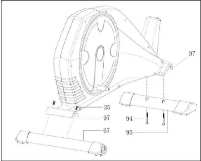
97 35 97 67 94 95Fig.2
text_image
Technical diagram of a mechanical device with numbered parts and exploded views, likely for assembly or maintenance instructions.Fig.3
text_image
Technical diagram of a stationary exercise machine with numbered components for identification.Fig.4
text_image
Technical diagram of an exercise machine with numbered components and labeled parts in ChineseFig.5
text_image
Technical diagram of an exercise machine with numbered components and a detailed inset view showing internal structure details.Fig.6
text_image
Technical diagram of an exercise bike with labeled components and motion indicatorsFig.7
Fig.8
text_image
Technical diagram of an exercise bike with labeled components and exploded views
text_image
Technical diagram of an exercise bike with numbered components and exploded view showing internal wiring connectionsFig.9
text_image
Technical diagram of an exercise machine with numbered components for identificationFig.10
Fig.11
natural_image
Technical line drawing of a mechanical device with a labeled component '67A' (no readable text or symbols beyond label)
text_image
95WFig.12
text_image
97 113 220 V k mEspañol
line
| AGE | HEART RATE | | --- | ---------- | | 20 | 160 | | 40 | 120 | | 75 | 100 |Consult your doctor before starting any exercise program. It is advisable to undergo a complete physical examination.
Work at the recommended exercise level, do not overexert yourself. If you feel any pain or discomfort, stop exercising immediately and consult your doctor.
Use the appliance on a solid, fl at surface, with some type of protection for the floor or carpet. In the interest of safety, the equipment must have at least 1 metre of free space around it. Do not allow children to play with the equipment or in the immediate vicinity. Keep your hands well away from any of the moving parts.
Check the elliptical trainer before starting the exercise; to make sure that all of the parts are attached and that the nuts, bolts, pedals and focus bars have been tightened correctly prior to use.
Any adjustment device that could interfere with the user's movement should not be left projecting.
People should be careful with the joint place between pedal tubes and swing bar tubes. If fingers get stuck, injuries could be caused.
Wear appropriate clothing and footwear for the exercise. Do not use loose clothing. Do not wear leather soled shoes or footwear with high heels.
This appliance has been tested and it complies with standard EN957 under class H.B., suitable for domestic use only. Maximum user weight 105kg. Braking is independent of speed.
IMPORTANT.-
Read the instructions carefully before proceeding to assemble the equipment. Remove all the parts from the cardboard packaging and check them against the parts list to ensure that there is nothing missing.
Do not throw the cardboard away until the elliptical trainer is fully assembled.
Always use the appliance in accordance with the instructions. If you discover any defective component while assembling or checking the equipment, or if you hear any strange noise during exercise then stop. Do not use the appliance until the problem has been resolved.
EXERCISE INSTRUCTIONS.-
Use of the ELLIPTICAL TRAINER offers various benefits; it will improve fitness, muscle tone and when used in conjunction with a calorie controlled diet it will help you to lose weight.
1, Warm-up phase
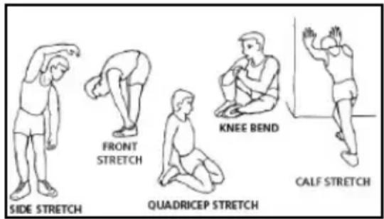
This phase speeds up the body's blood circulation and gets the muscles ready for exercise. It also reduces the risk of cramp and sprains. It is advisable to do some stretching exercises, as shown below. Each stretch should last approximately 30 seconds, do not overexert the muscles. If you feel pain, STOP.
text_image
SIDE STRETCH FRONT STRETCH QUADRICEP STRETCH KNEE BEND CALF STRETCH2. Exercise phase
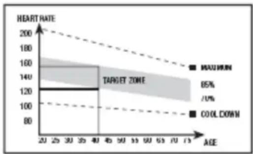
This phase requires the greatest physical exertion. After regular exercise the leg muscles will become more flexible. It is important to keep the rhythm constant. The rhythm of the exercise should be fast enough to bring the heart rate into the target area, as shown on the following graph:
line
| AGE | HEART RATE | | --- | --- | | 20 | 120 | | 30 | 120 | | 40 | 120 | | 50 | 120 | | 60 | 120 | | 70 | 120 |This phase should last at least 12 minutes, although it is advisable for most people to start off with sessions of 10-15 minutes.
3. Cool-down phase
This phase allows the cardiovascular and muscle system to relax. It consists of repeating the warm-up exercises, i.e. reducing the rhythm and continuing for approximately 5 minutes. Repeat the stretching exercises but remember not to overexert the muscles.
Eventually your training sessions will have to become longer and more intensive. It is advisable to exercise at least three days per week, on alternate days.
Muscle toning
You should select a high exertion level in order to tone muscles during exercise. This entails greater stress on the leg muscles, so it may be wise to reduce exercise times. If you also wish to improve your overall fi tness then you should change your training program. Do the warm-up and cooldown exercises as normal but when you are reaching the end of the exercise phase, increase the exertion level in order to make your legs work harder. You should reduce speed in order to keep your heart rate within the target area.
Weight loss
In this case the important factor is the effort made. The more intense and the longer the session, the greater the number of calories burned. Even though you are doing the same work as you do to improve fitness, the objective has changed.
GENERAL INSTRUCTIONS.-
Carefully read through the instructions contained in this manual. It provides you with important information about assembly, safety and use of the machine.
1 This unit has been designed for home use. The user weight does not have to exceed 125kg
2 Keep your hands well away from any of the moving parts.
3 Parents and/or those responsible for children should always take their curious nature into account and how this can often lead to hazardous situations and be haviour resulting in accidents. This unit does not have to be used in any case like toy.
4 The owner is responsible for ensuring that anyone who uses the machine is duly informed about the necessary precautions.
5 Your unit can only be used by one person at a time.
6 Use suitable clothing and footwear. Tie up your shoelace correctly.
1. ASSEMBLY INSTRUCTIONS.-
Take the unit out of its box and make sure that all of the pieces are there:
The assistance of a second person is recommended when assembling this unit.
(97) Main body.
(24) Main post.
(106) Handlebar tube.
(95) Front stabiliser bar with wheels.
(67) Rear stabiliser bar with adjustable feet.
(51L) Left footrest.
(51R) Right footrest.
(48L) Pedal left foot.
(48R) Pedal right foot.
(16L) Top focus bar, left.
(16R) Top focus bar, right.
(1) Monitor.
(21L) Bottom trim covers, left and right. (L) for the knuckle joints on the focus bars.
(21R) Bottom trim covers, left and right
(R) for the knuckle joints on the focus bars.
(52) Bottom cover, left foot.
(52) Bottom cover, right foot.
(102) Bottom post cover.
(8L) Post cover L.
(8R) Post cover R.
(113) Transformer.
2. FITTING THE STABILISER BARS.-
Bring the front stabiliser bar with wheels (95) to the main body (97) positioning the wheels at the front of the unit, Fig.1, insert screws (52) and tighten securely.
Take the rear stabiliser bar with adjustable feet (67), Fig.1, insert the bolts (35) and tighten securely.
3. FITTING THE BOTTOM POST COVER.-
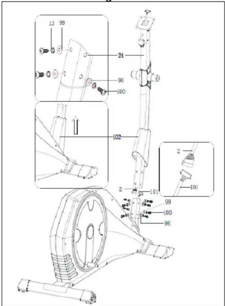
Take the main post (102) and insert the bottom post cover (24) in the direction of the arrow, Fig.2.
4. FITTING THE MAIN POST.-
Once the bottom post cover, is fitted, remove the screws (100) and washers (98) and (99) from the bottom of the main post (24).
Bring the main post (24) up to boss on the main body (97), Fig.2.
Plug connector (2), coming out of the main post (24), into connector (101), coming out of the boss on the main body (97), Fig.2.
Slip the main post (24) over the boss (97) on the main body in the direction of the arrow, Fig.2, making sure not to snag any of the cables.
Lower the bottom trim section (102) for the main post (24) down over the boss section of the main body (97), Fig.2.
5. FITTING THE FOCUS BARS.-
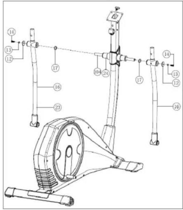
Insert the focus bar spindle (104) through the spacer bushes on the main post (24), Fig.3, leaving it centred.
Fit the spacer washers (17) as shown in Fig.3. Insert the left focus bar (16L) (marked with the letter “L”) onto the focus bar spindle (104), Fig.3, then fit the right focus bar (16R) (marked with the letter “R”) on the other end of the spindle. Fit the washed bolts (14) and the flat washers (12-13) and with the help of the box spanners tighten securely.
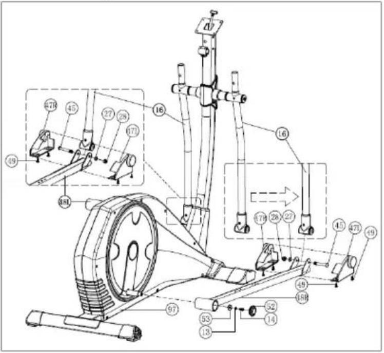
Take the right pedal (48R), Fig.4, (marked with the setter "R") and slide it onto the crank shaft on the right-hand side of the machine.
Now take washer (13-53) and bolt (14) and tighten securely.
Attach the bottom cover for the right foot (52), Fig.4.
Take the left pedal (48L), Fig.4, (marked with the setter “L”) and slide it onto the shaft on the left-hand side of the machine.
Now take washer (13-53) and bolt (14) and tighten securely.
Attach the bottom cover for the left foot (52), Fig.4.
7. FITTING THE FOOT BARS.-
Take the right foot bar (48R) and position it on the "U" at the bottom of the right focus bar (16R), Fig.4. Insert screw (45), as shown in Fig.4, then fit the flat washer (27) and the self locking nut (28), and tighten securely. Take the left foot bar (48L) and go through the same assembly procedure as with the right.
8. FITTING THE FOCUS BAR SID COVERS TO THE FOOT BARS.-
Next fit the footrest covers (47L) & (47R) with the bottom of the joints on the right side, Fig.4. Use screws (49) to screw them together. Then do the same with the other covers (47L) & (47R) on the left-hand side.
9. FITTING THE FOOTRESTS.-
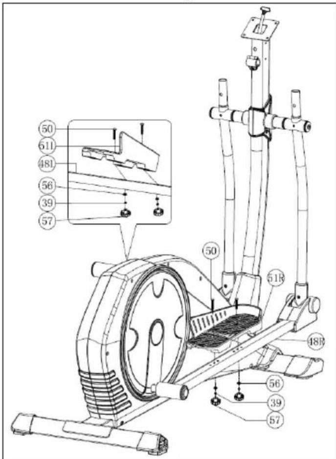
Next, remove the screws (50), the flat washers (39-56) and the nuts (57) and position the right footrest (51R marked with the letter "R") on top of the unit's right foot (48R), Fig.5, (left and right refers to the user's position doing exercise) refit the screws (57), the washers (39-56) and the screws (50) removed previously and tighten securely.
Next, position the left footrest (51L marked with the letter "L") on top of the left foot (48L), refit the nuts (57), the washers (39-56) and the screws (50) removed previously and tighten securely.
10. FITTING THE UPPER FOCUS BARS.-
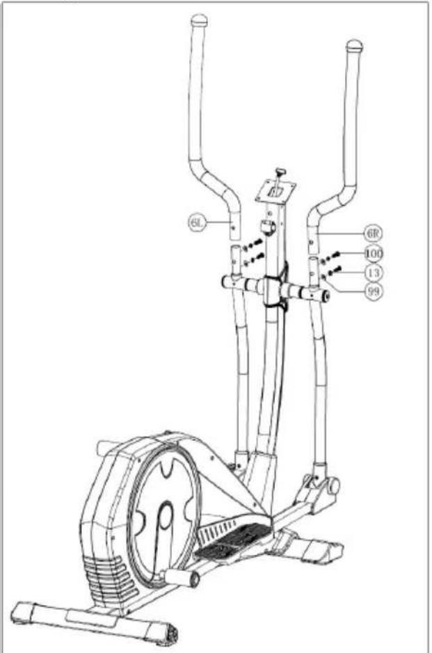
Take the top left bar (6L) (marked with the letter "L"). Insert the top bar onto the bottom left focus bar (16L), lining up the letters (L), Fig.6, fit the screws (100), the cap nuts (13-99) and tighten securely. Now go through the same procedure for the top right focus bar (6R).
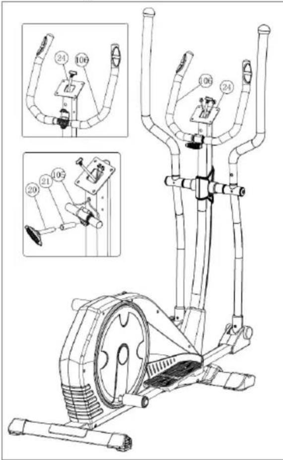
11. FITTING THE HANDLEBAR.-
Insert the hand-grip cable (105) in through the slot, as shown in Fig.7, and pull it out through the top of the focus bar support (24), as shown in Fig.7.
Take the handlebar (106), remove screws (20), position the ends of the Handlebar on the plate at the top of the main post (24), Fig.7. Refit the screws (20) removed previously.
12. FITTING MONITOR.-ATTACHING THE FEEDBACK CABLE.
Take hold of the cable (2), which is sticking up out of the main post (24), Fig.8, and plug it into the connector of the electronic unit (1), as shown in Fig.8.
FITTING THE HAND-GRIP CABLE.
Take hold of the Hand-grip connectors (105), sticking out of the main post (24), and plug them into the
connectors located at the back of the monitor (1), as shown in Fig.8.
ATTACHING THE MONITOR.-
Release screws (3), Fig.8, at the back of the monitor.
Next, slide the front of the monitor onto the plate on top of the main post (24) in the direction of the arrow, Fig.8, push the cables down into the main post making sure not the pinch any of the cables. Replace the screws (3) removed previously.
13. FITTING THE CENTRAL COVERS.-
Take post cover L (8L) and post cover R (8R) and position them on the main post (24), Fig.8. Now use the screws (9) to attach them to the post.
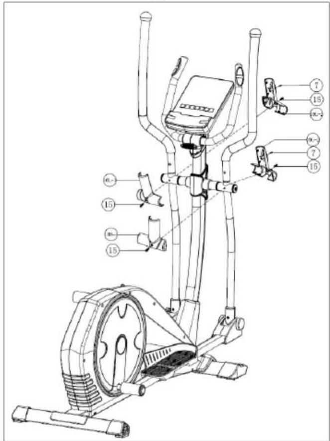
14. FITTING THE FOCUS BAR SIDE COVERS.-
Take the covers (10R), marked on the inside with the letter "R", and position them at the spindle end with the bars on the right hand side, as shown in Fig.9. Now use screws and (7-15) to attach them. Carry out the same procedure at the other end of the bar using the covers (10L) marked on the inside with the letter "L".
ATTENTION: It is important to retighten all of the screws involved in assembling the machine after approximately a week of use as this will prevent any strange noises and possible damage.
LEVELLING.-
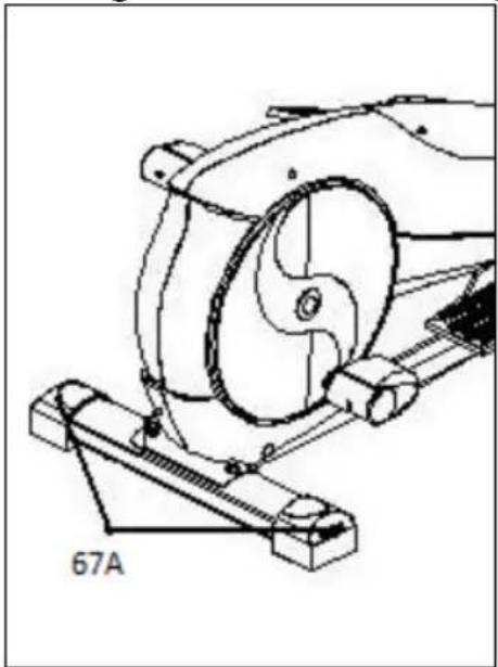
Once the unit has been placed into its final position, make sure that it sits flat on the floor and that it is level. This can be achieved by screwing the adjustable feet (67A) up or down, as shown in Fig.10.
MOVEMENT & STORAGE.-
The unit is equipped with wheels (95W) to make it easier to move. The wheels located at the front of your unit make it easier to move it into a chosen position, by lifting the rear of the unit up slightly and pushing it, as shown in Fig.11. Store your unit in a dry place, preferably not subject to changes in temperature.
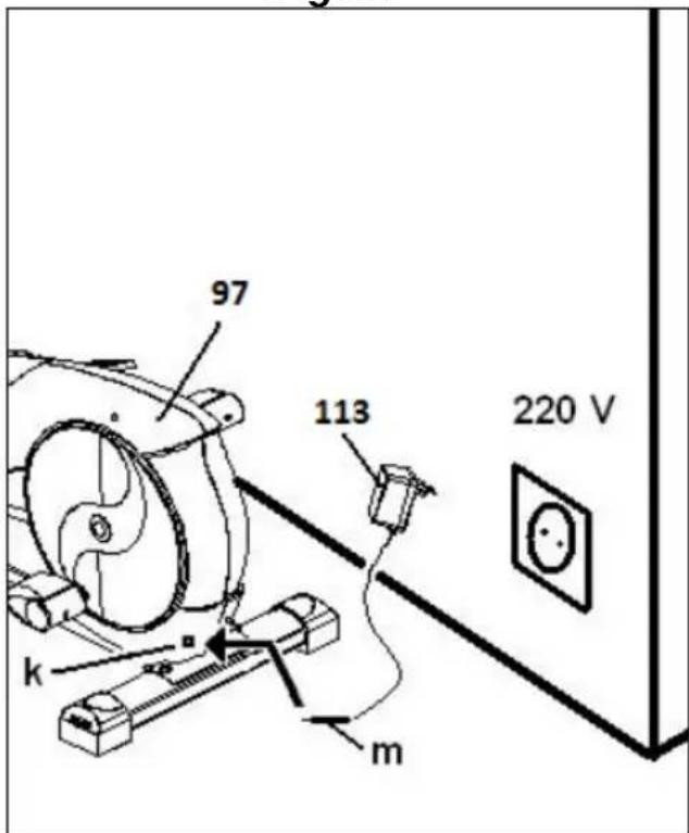
MAINS CONNECTION.-
Insert the jack (m) on the transformer (113) into the connection hole (k) on the main body (97) (bottom, rear of the machine) and then plug the transformer into a 220 V mains supply, Fig.12.
THE MANUFACTURER RESERVES THE RIGHT TO MODIFY THE SPECIFICATIONS OF ITS PRODUCTS WITHOUT PRIOR NOTICE
Do not hesitate to get touch with the Technical Assistance Service if you have any queries by phoning customer services (see last page in manual)
Français
line
| AGE | HEART HATE | | --- | --- | | 20 | 140 | | 35 | 120 | | 40 | 100 | | 55 | 100 | | 60 | 100 | | 75 | 100 |line
| AGE | HAWLI RATE | | --- | --- | | 20 | 140 | | 30 | 120 | | 40 | 100 | | 50 | 100 | | 60 | 100 | | 70 | 100 | | 75 | 100 |line
| AGE | HEART RATE | | --- | --- | | 20 | 120 | | 35 | 120 | | 40 | 120 | | 55 | 120 | | 60 | 120 | | 75 | 120 |line
| AGE | HEART RATE | | --- | --- | | 20-40 | 120 | | 40-60 | 140 | | 60-75 | 160 |To order replacement parts: State the part code and Quantity
text_image
Exploded view diagram of a mechanical device with numbered components and labeled parts, including 11 items and Item 113.To order replacement parts: State the part code and Quantity
text_image
Exploded view diagram of a mechanical device with numbered components and labeled parts, including motor, wheels, and accessories.To order replacement parts: State the part code and Quantity
e-mail: info@bhfitness.pt
BH SERVICE PORTUGAL
Tel.: +351 234 729 510
e-mail: info@bhfitness.pt
BH GERMANY GmbH
Grasstrasse 13
45356 ESSEN
GERMANY
Tel: +49 2015 997018
e-mail:
technik@bhgermany.com
BH FITNESS NORTH AMERICA
20155 Ellipse
Foothill Ranch
CA 92610
Tel: + 1 949 206 0330
Toll free: +1 866 325 2339
No.80, Jhongshan Rd.,
Daya Dist.,
Taichung City 42841,
Taiwan. R.O.C.
Tel.: +886 4 25609200
Fax: +886 4 25609280
Block A, NO.68, Branch Lane
455, Lane 822,
Zhen Nan RD., Li Zi Yuan, Putuo,
Shanghai 200331, P.R.C.
Tel: +86-021-5284 6694
Fax:+86-021-5284 6814
e-mail: info@i-bh.cn
BH FITNESS UK
Tel: 02037347554
e-mail:
sales.uk@bhfitness.com
AFTER SALES – UK
Tel.: 02074425525
e-mail:
service.uk@bhfitness.com
BH FITNESS FRANCE
SAV FRANCE
Tel : +33 0810 000 301
Fax : +33 0810 000 290
savfrance@bhfitness.com
BH SE RESERVA EL DERECHO A MODIFICAR LAS ESPECIFICACIONES DE SUS PRODUCTOS SIN PREVIO AVISO.
SPECIFICATIONS MAY BE CHANGED WITHOUT PRIOR NOTICE DUE TO OUR PROGRAMME OF CONTINUOUS PRODUCT DEVELOPMENT.
BH SE RÉSERVE LE DROIT DE MODIFIER LES SPECIFICATIONS DE SES PRODUITS SANS PRÉAVIS.