
PA1120DMT - Audio module Monacor - Free user manual and instructions
Find the device manual for free PA1120DMT Monacor in PDF.
| Product type | Message memory audio module |
| Brand | Monacor |
| Model | PA1120DMT |
| Dimensions (W × H × D) | 194 × 40 × 85 mm |
| Weight | 270 g |
| Power supply | 15-17 V DC, 150 mA |
| Memory capacity | 6 × 2176 KB (M1-M6, 360 s each) + 20 × 128 KB (Voice01-20, 23 s each) |
| Main functions | Message recording and playback, DCF77 radio clock, time programming, remote playback, emergency announcement, microSD memory card support |
| Audio input | 3.5 mm jack, MIC (2.5 mV / 600 Ω) or LINE (245 mV / 10 kΩ) |
| Bandwidth | MIC: 150-15000 Hz, LINE: 50-15000 Hz |
| Headphone output | 3.5 mm jack, 24 mW max into 64 Ω |
| Display | Digital screen |
| Operating temperature | 0-40 °C |
| Maintenance and cleaning | Clean with a dry, soft cloth; do not use chemicals or water |
| Safety | Installation by qualified personnel, indoor use, disconnect if damaged |
| Spare parts and repairability | Repair by specialized technician only; compatible with PA-1120RC, PA-6000RC, PA-2400RC control microphones |
| General information | Manual available in several languages, free download at notice-facile.com |
Frequently Asked Questions - PA1120DMT Monacor
User questions about PA1120DMT Monacor
0 question about this device. Answer the ones you know or ask your own.
Ask a new question about this device
Download the instructions for your Audio module in PDF format for free! Find your manual PA1120DMT - Monacor and take your electronic device back in hand. On this page are published all the documents necessary for the use of your device. PA1120DMT by Monacor.
USER MANUAL PA1120DMT Monacor
Message Storage Insertion Module with Radio Clock

text_image
MONACOR WWW.MONACOR.COM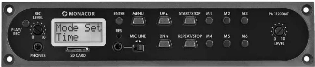
text_image
MONACOR MODE Set Time REC LEVEL PLAY/ REC 0 10 PHONES SD CARD ENTER MENU UP START/STOP M1 M2 M3 PA-1120DMT RES MIC LINE DN REPEAT/STOP M4 M5 M6 0 10 LEVELPA-1120DMT
INSTALLATION and OPERATING INSTRUCTIONS
NOTICE DE MONTAGE et D'UTILISATION
ISTRUZIONI PER IL MONTAGGIO e PER L'USO
INBOUW- en GEBRUIKSHANDLEIDING
English ...... Page 14
Français ...... Page 24
Italiano....Pagina 34
| Mon | Montag | (Monday) |
| Tues | Dienstag | (Tuesday) |
| Wednes | Mittwoch | (Wednesday) |
| Thurs | Donnerstag | (Thursday) |
| Fri | Freitag | (Friday) |
| Satur | Sonnabend | (Saturday) |
| Sun | Sonntag | (Sunday) |
Message Storage Insertion Module with Radio Clock
These instructions are intended for technicians installing the module and for users without any specific technical knowledge. Please read the instructions carefully prior to operation and keep them for later reference.
All operating elements and connections described can be found on the fold-out page 3.
Contents
1 Control Elements and Connections. 14
2 Safety Notes. 15
3 Applications 15
3.1 Storage capacity ..... 16
4 Installation and Connections ..... 16
4.1 DCF77 module (fig. 2). . . . . . . . . 16
5 Basic Settings 17
5.1 Selecting the emergency trigger signal. 17
5.2 Selecting the replay mode ..... 17
5.3 Setting the clock manually ..... 17
5.4 Increasing the output level ..... 17
6 Operation 18
6.1 Recording.... 18
6.1.1 Storage locations M1–M6 ..... 18
6.1.2 Storage locations Voice01-Voice20. 18
6.2 Replay 19
6.2.1 Storage locations M1–M6 ..... 19
6.2.2 Calling up a message by remote control ..... 19
6.2.3 Storage locations Voice01-Voice20. 20
6.3 Deleting a message ..... 20
6.4 Message sequence ..... 20
6.4.1 Programming a message sequence . 20
6.4.2 Replaying a message sequence . . . 21
6.5 Time-controlled replay. 21
6.5.1 Creating a schedule....21
6.5.2 Changing or deleting program data . 22
6.5.3 Copying a day schedule ..... 22
6.6 Memory card ..... 22
6.6.1 Replaying an audio file ..... 22
6.6.2 Copying an audio file ..... 23
7 Specifications 23
1 Control Elements and Connections
1 Button PLAY/ REC to switch between replay and recording for the messages M1 – M6
2 Control REC LEVEL to adjust the recording level
3 Headphone connection PHONES (3.5 mm jack; mono, left side only for stereo headphones), minimum impedance of the headphones 64 Ω When this jack is used, the output "Audio Out" (26) to the amplifier will be muted.
4 Display
5 Slot for a memory card (type "microSD")
6 Button ENTER to call up a menu item and to confirm an entry
7 Audio input (2-pole 3.5 mm jack) to connect a microphone or an audio source with line output level for recording a message
8 Recessed reset button for the microprocessor of the insertion module (use a thin, non-conductive object to press the button)
The processor will be reset (as it is after the power supply was interrupted). This reset will not apply to the message memory and the program memory.
9 Switch MIC / LINE to select the input sensitivity for the audio input (7)
10 Button MENU to call up or cancel a setting menu
11 Button DN to reduce the number of repeats for the replay of a selected message, to select a menu item and to reduce a value to be set
12 Button UP to increase the number of repeats for the replay of a selected message, to select a menu item and to increase a value to be set
13 Button REPEAT/ STOP to start and stop the replay of a message M1 – M6 with the repeats set
14 Button START/ STOP to start and stop the one-time replay of a message M1 - M6
15 Buttons M1 – M6 to select a storage location for recording or replaying a message
16 Control LEVEL to adjust the volume of the replay
17 DCF77 radio clock receiver
18 Connection plate to be mounted on the rear side of the amplifier
19 Jumper J1 to adjust the output level (position hi = +10 dB)
20 Switching input to trigger the replay of an emergency message (M6); to be connected to the corresponding connection cable of the amplifier
21 Additional audio output with a stereo signal (not required when used with amplifiers from MONACOR)
22 Jumper PLAY MODE SELECTOR to select the replay mode for the messages M1 – M6
replay after the button START/ STOP (14) or REPEAT/ STOP (13) was pressed
immediate (multiple) replay when the message is selected by means of the buttons M1–M6 (15)
23 Additional input for DCF77 radio clock signals [not required when used with amplifiers from MONACOR as the connection is made via the terminals of the connection plate (18)]
24 Connection jack for remote control of the module via the zone paging microphone PA-1120RC, PA-6000RC or PA-2400RC; connect the jack to the corresponding connection cable of the amplifier
25 Jack for connection to the connection plate (18) via the ribbon cable supplied
26 Jack for power supply and for the audio output; to be connected to the corresponding connection cable of the amplifier
27 "Busy" LED, will light up during recording and replay
2 Safety Notes
The insertion module corresponds to all relevant directives of the EU and is therefore marked with €€
- The insertion module must be installed by skilled personnel only.
- The insertion module is suitable for indoor use only. Protect it against dripping water and splash water, high air humidity and heat (admissible ambient temperature range: 0 – 40 °C).
- Do not operate the unit with the installed insertion module and immediately disconnect the unit from the power supply
- if the insertion module, the unit or the mains cable is visibly damaged,
-
if a defect might have occurred after the unit was dropped or suffered a similar accident,
-
if malfunctions occur.
In any case the insertion module or the entire unit must be repaired by skilled personnel.
- For cleaning only use a dry, soft cloth; never use water or chemicals.
- No guarantee claims for the insertion module and no liability for any resulting personal damage or material damage will be accepted if the insertion module is used for other purposes than originally intended, if it is not correctly installed or operated, or if it is not repaired in an expert way.

If the insertion module is to be put out of operation definitively, take it to a local recycling plant for a disposal which is not harmful to the environment.
3 Applications
The insertion module PA-1120DMT is a message storage module for storing and replaying 26 voice messages. Using a memory card (type "microSD [HC]"), externally created recordings can be copied to the memory of the insertion module. The integrated clock with a DCF77 radio clock receiver allows for time-controlled message replay. For remote-controlled message replay and for emergency message replay, switching contacts can be used. The insertion module has been especially designed for PA systems and is suitable for installation e.g. in the following units from MONACOR:
| PA-1120PA-1240 | PA amplifier for 5 zones |
| PA-1200 PA | A amplifier for 4 zones |
| PA-1200EX | Basic unit for 2 insertion modules |
| PA-2410ZPA-2420Z | PA amplifier for 10 zonesPA amplifier for 20 zones |
| PA-5240PA-5480 | PA amplifier for 5 zones |
| PA-6240PA-6480PA-6600 | PA amplifier for 6 zones |
3.1 Storage capacity
The insertion module provides 6 storage locations ("M1" to "M6") with 2176 kBytes each which corresponds to a recording time* of 360 seconds for each message. These messages can be called up automatically via the integrated clock, the buttons (15), the switching contacts on the connection plate (18) or via buttons of the zone paging microphone, PA-1120RC, PA-6000RC or PA-2400RC (in combination with an amplifier). The storage location "M6" is reserved for an emergency message that is automatically started via the amplifier [connection "E / M TRIGGER INPUT" (20)] or via a normally open contact at the terminals "EMERGENCY" on the connection plate (18).
In addition, 20 storage locations ("Voice01" to "Voice20") with 128 kBytes each are available which corresponds to a recording time* of 23 seconds for each message. These messages can be called up automatically via the integrated clock or manually via the menu.
Additionally, a program may be created to replay any stored messages one after the other.
* Different maximum recording times may apply to externally created recordings.
4 Installation and Connections
WARNING

Prior to installing the insertion module, disconnect the mains plug of the amplifier or basic unit from the mains socket. Otherwise, there is a risk of electric shock.
1) Remove the housing cover from the amplifier or basic unit.
2) Remove the insertion compartment cover from the front side of the amplifier or basic unit.
3) Prior to installing the insertion module PA-1120DMT into the amplifiers PA-1120, PA-1240, PA-2410Z, PA-2420Z, PA-6240, PA-6480 and PA-6600, rearrange the jumper MS2 to the position PRI (see instructions of the amplifier); thus, other signals will not reduce the volume of announcements made by PA-1120DMT.
4) Insert the insertion module, and then fasten it using screws.
5) Connect the plug of the exposed 3-pole cable of the amplifier or basic unit to the jack "POWER IN / +, G, Audio Out" (26) of the insertion module. This will supply the insertion module with 17 V -- and will send the audio signal to the amplifier.
6) To trigger the replay of a stored emergency message via the alarm input of the amplifiers PA-1120, PA-1240, PA-2410Z, PA-2420Z, PA-6240, PA-6480 and PA-6600:
The PCB which is completely at the left of the rear panel of the amplifier has a connection AS104 (AS-603 for PA-2410Z and PA-2420Z) with a two-pole line with a black core and a brown core. Connect the bare end of this line to the pin housing CN104 of the insertion.
7) To install the connection plate (18), remove the cover plate from the rear side of the amplifier or basic unit. Screw the connection plate to the amplifier or basic unit from the outside and then connect it to the jack DCF-77/ REMOTE CONTROL (25) using the ribbon cable supplied.
8) To operate the insertion module with a zone paging microphone PA-1120RC, PA-6000RC or PA-2400RC (e. g. with the amplifier PA-2410Z), connect the plug of the 10-pole cable to the jack TO RR-100 / 600 (24). This cable is used to call up messages via the zone paging microphone.
4.1 DCF77 module (fig. 2)
Connect the connection cable of the reception module (17) supplied to the three terminals "DCF-77" of the connection plate (18):
| Connection cable Terminal | |
| white wire DATA | |
| red wire | +5V |
| shield GND | |
Important! Never place the reception module in a metal housing (e. g. rack). Nearby metal parts or electromagnetic fields (transformers, computers, power lines etc.) may interfere with radio signal reception. If applicable, place the receiver at a different location.
When a time signal is received, DCF77 ON will appear on the display (4) every full minute.
5 Basic Settings
5.1 Selecting the emergency trigger signal
The type of trigger signal can be selected for remote-controlled retrieval of an emergency message via the amplifier [connection "E/M TRIGGER INPUT" (20)] or via the terminals "EMERGENCY" on the connection plate (18).
Note: This selection is exclusively made for the emergency announcement triggered via the connection "E/M TRIGGER INPUT" or via the terminals "EMERGENCY". It will not affect any other announcements.
1) Switch on the amplifier or the basic unit.
2) Press the button MENU (10). The display (4) will show:
Mode Set
Time
3) Press the button UP (12) or DN (11) repeatedly until EM Type appears on the lower line of the display.
4) Press the button ENTER (6). EM Type will now appear on the first line of the display; the lower line will show the current trigger type setting.
5) Use the button UP or DN to select the trigger type and then press the button ENTER to confirm:
Latch The message will be repeated as long as the trigger signal is available.
Pulse The message will be repeated until the button START/ STOP (14) is pressed.
To stay with the current trigger type, cancel the setting by means of the button MENU.
Note: The menu will be automatically exited after approx. 30 seconds if no button is pressed.
5.2 Selecting the replay mode
The replay of messages stored on the six main storage locations usually consists of two steps:
- Selecting the message
- Starting the (multiple) replay
This applies both to the replay via the buttons on the insertion module (chapter 6.2.1) and to the (remote-controlled) replay via switching contacts (chapter 6.2.2).
For immediate message replay, rearrange the jumper PLAY MODE SELECTOR (22). Switch off the unit prior to rearranging the jumper.
replay after the button START/ STOP (14) or REPEAT/ STOP (13) was pressed
immediate (multiple) replay when the message is selected by means of the buttons M1–M6 (15)
5.3 Setting the clock manually
The clock can be manually set if synchronisation of the integrated clock via the wireless transmitter is not possible or not desired.
1) Switch on the amplifier or the basic unit.
2) Press the button MENU (10). The display (4) will show:
Mode Set
Time
3) Press the button ENTER (6). Week Set will now appear on the first line of the display; the lower line will show the current weekday setting.
4) Use the button UP (12) or DN (11) to set the weekday desired:
Mon Monday
Tues Tuesday
Wednesday Wednesday
Thurs Thursday
Fri Friday
Satur Saturday
Sun Sunday
5) Press the button ENTER. Time Set will appear on the first line of the display; the lower line will show Hour: and the current hour setting.
6) Use the button UP or DN to set the hour and then press the button ENTER to confirm. The lower display line will now show Min: and the current minute setting.
7) Use the button UP or DN to set the minute and then press the button ENTER to confirm. The display will now show the weekday and the time set.
When a time signal is received, DCF?? ON will appear on the display and the clock will be synchronised.
5.4 Increasing the output level
If required, the output level can be increased by 10 dB: Switch off the unit and then rearrange the jumper J1 (19) from the position "low" to the position "hi".
6 Operation
When the amplifier or the basic unit is switched on, the display (4) of the insertion module will show the weekday and the time. The unit will always automatically return to this indication after 30 seconds when, for example, no button is pressed in a menu. To cancel a menu setting at any time, press the button MENU (10).
6.1 Recording
To record a message, connect a microphone or a mono audio source with line level to the 2-pole jack (7) and set the switch (9) for the input sensitivity to the corresponding position: MIC (microphone) or LINE (line level).
During recording, the input signal will be replayed via the amplifier. However, it is also possible to use headphones for monitoring the input signal: Connect the headphones (minimum impedance: 64 Ω) to the jack PHONES (3) [mono, only the left side for stereo headphones); the output (26) to the amplifier will be muted.
Please refer to chapter 6.6 for information on how to use externally created recordings.
6.1.1 Storage locations M1–M6
To record a message on one of the storage locations "M1" to "M6":
1) Press the button (15) of the storage location desired. The display will show, for example: M3
PlayMode
If pressing this button starts the replay of the stored message, press the button REPEAT/ STOP (13) to stop the replay.
2) Press the button PLAY/ REC (1). The display will switch to the recording mode:
M3
Rec Mode
3) Press the button START/ STOP (14). First, Erase will appear on the lower line of the display and the storage location will be cleared.
Recording will start when the first line of the display shows REC, following the storage number. On the lower line, a bar graph will appear, indicating the level of the input signal.
4) Use the control REC LEVEL (2) to adjust the level of the signal to be recorded in such a way
that not all segments of the bar graph will be shown for peaks.
5) To stop the recording, press the button START/STOP.
6.1.2 Storage locations Voice01 – Voice20
To record a message on one of the storage locations "Voice01" to "Voice20":
1) Press the button MENU (10). The display will show:
Mode Set.
Time
2) Press the button UP (12) or DN (11) repeatedly until Voice appears on the lower line of the display.
3) Press the button ENTER (6). The display will now show:
Choose
Play
4) Use the button UP or DN to select the option Rec on the lower line.
5) Press the button ENTER. The display will now show:
Record
Voice:01
6) Use the button UP or DN to select the storage location desired for the recording (01 to 20).
7) Press the button START/ STOP (14) or ENTER. First, Erase will appear on the lower line of the display and the storage location will be cleared.
Recording will start when Erase disappears. A bar graph will appear instead, indicating the level of the input signal.
8) Use the control REC LEVEL (2) to adjust the level of the signal to be recorded in such a way that not all segments of the bar graph will be shown for peaks.
9) To stop the recording, press the button START/ STOP or ENTER.
Now, Playback will appear on the display; the button START/ STOP can be pressed to immediately replay the message stored. To select a different storage location for replay, use the button UP or DN (chapter 6.2.3).
To exit the menu, press the button MENU.
6.2 Replay
Use the control LEVEL (16) to adjust the volume of the messages replayed. Prior to the first message replay, turn the control approx. to mid-position and, if required, adjust the control during replay. If the volume of the insertion module is too low for the amplifier used even though the control has been turned to the right stop, the output level may be increased by another 10 dB (chapter 5.4).
If an emergency message is to be replayed automatically, make absolutely sure to prevent any inadvertent readjustment of the control.
Headphones can be used to monitor a stored message: Connect the headphones (minimum impedance: 64 Ω) to the jack PHONES (3) [mono, only the left side for stereo headphones]; the output (26) to the amplifier will be muted.
6.2.1 Storage locations M1–M6
The following description applies to the normal replay mode. Please refer to chapter 6.2.1.1 for the immediate replay mode.
For one-time replay of a message that has been recorded on one of the storage locations "M1" to "M6":
1) Press the button (15) of the storage location desired. The display will show, for example:
M3 Rep2 PlayMode
2) Press the button START/ STOP (14). The replay will start and Playing will appear on the lower display line.
3) To stop the replay, press the button START/ STOP again.
For multiple replay of a recorded message:
1) Press the button of the storage location desired. The display will show, for example:
M3 Rep2 (storage location M3, PlayMode replayed twice)
2) Use the button UP (12) or DN (11) to define the number of message repeats: Ref1 to Ref9 = replayed 1 to 9 times, Ref0 = repeated continuously.
3) Press the button REPEAT/ STOP (13). The replay will start and Playing will appear on the lower display line.
4) To stop the replay, press the button REPEAT/STOPagain.
At a zone paging microphone PA-2400RC, PA-1120RC or PA-6000, it is also possible to select a message M1 – M6 and then to start the replay by means of the button START/ STOP or to start multiple replay by means of the button REPEAT/ STOP.
6.2.1.1 Immediate replay
If immediate replay has been selected by means of the jumper PLAY MODE SELECTOR (▶ chapter 5.2):
1) Press the button (15) of the storage location desired. The display will now show, for example:
1) M3 Ref2 (storage location M3, Playing 9 replayed twice)
The (multiple) replay will start immediately. The number of replays will be indicated next to the storage location.
2) To stop the replay, press the button REPEAT/STOP (13).
3) When the replay has been stopped, the button UP (12) or DN (11) can be used to change the number of message repeats:
ReP1 to ReP9 = replayed 1 to 9 times, ReP0 = repeated continuously.
6.2.2 Calling up a message by remote control
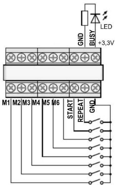
Instead of the buttons of the insertion module (cf. chapter 6.2.1), the switching contacts on the connection plate (18) can be used to replay the messages that have been recorded on the storage locations "M1" to "M6": Briefly connect the terminal with the name of the corresponding button (M1, ... M6, START [/STOP], REPEAT [/STOP]) to the terminal GND (via a normally open contact). The number of repeats for multiple message replay, however, can only be changed via the buttons UP (12) and DN (11).
Use the terminal BUSY to externally indicate insertion module activity [analogous to the LED indicator (27) on the circuit of the insertion module that lights up when a message is being recorded or replayed]. In this case, the terminal will provide 3,3V= against GND, and an LED, for example, can be connected via a suitable series resistor (fig. 5, page 20).
English
text_image
GND BUSY LED +3,3V M1 M2 M3 M4 M5 M6 START REPEAT GND⑤ Connection for remote control
6.2.3 Storage locations Voice01—Voice20
To replay a message from one of the storage locations "Voice01" to "Voice20":
1) Press the button MENU (10). The display will show: Mode Set Time
2) Press the button UP (12) or DN (11) repeatedly until Voice appears on the lower display line.
3) Press the button ENTER (6). The display will now show: Choose Play
4) Press the button ENTER. The display will now show: Playback Voice:01
5) Use the button UP or DN to select the message desired (☐1 to ☐20).
6) Press the button START/ STOP (14) or ENTER. Playing will appear on the first line of the display.
7) Press the button START/ STOP or ENTER to stop the replay. PlayBack will appear on the first line; a different message can be selected for replay (step 5).
6.3 Deleting a message
To delete a message from the storage locations Voice01 to Voice20 without recording a new message:
1) Press the button MENU (10). The display will show: Mode Set Time
2) Press the button UP (12) or DN (11) repeatedly until Voice appears on the lower display line.
3) Press the button ENTER (6). The display will now show: Choose Play
4) Use the button UP or DN to select the option Delete on the lower line.
5) Press the button ENTER. The display will now show: Delete Voice:01
6) Use the button UP or DN to select the message to be deleted (☐1 to 20) and then press the button ENTER to confirm.
The message will be deleted and the menu will be exited. To delete further messages, start with step 1 again.
Note: Messages that are stored on the storage locations M1 – M6 can only be deleted by a new recording (chapter 6.1.1).
6.4 Message sequence
A sequence of up to 20 stored messages may be programmed and manually replayed in any order.
6.4.1 Programming a message sequence
1) Press the button MENU (10). The display will show: Mode Set Time
2) Press the button UP (12) or DN (11) repeatedly until RECALL appears on the lower display line.
3) Press the button ENTER (6). The display will now show: RECALL PGM PLAY
4) Use the button UP or DN to select the option PGM Edit on the lower line.
5) Press the button ENTER. If no program has been created yet, the display will show:
PGM Edit P01 ---
6) Use the button UP or DN to select the storage location (M1-M6 or V01-V20 ["voice" storage]) for the first program step P01.
7) Press the button START/ STOP (14). Use the button UP or DN to select the storage location for the second program step P02.
8) Proceed in the same way to store all messages to be replayed in the desired order. Finally, press the button START/ STOP and then the button ENTER or wait for approx. 30 seconds until programming will be automatically finished.
Pressing the button ENTER will delete the program step most recently shown, delete the subsequent program steps and exit programming. Then the replay mode will be selected again (chapter 6.4.2).
Note: When program step 20 has been entered, wait for approx. 30 seconds to exit programming; pressing the button ENTER will delete all program steps.
6.4.2 Replaying a message sequence
1) Press the button MENU (10). The display will show:
Mode Set Time
2) Press the button UP (12) or DN (11) repeatedly until RECALL appears on the lower display line.
3) Press the button ENTER (6). The display will now show:
RECALL PGM Play
4) Press the button ENTER. The display will show, for example:
PGM Play P01 M6
5) Press the button START/ STOP (14). The replay will start and the display will now show:
PGM Play P01 ....
The programmed messages will be replayed one after the other and the indication of the program step replayed will change accordingly: P01, P02, P03, ...
6) To stop the replay, press the button START/ STOP again.
7) When the replay is started via the button RE-PEAT/ STOP (13), the replay will stop after each message. To start the subsequent message of the program, press the button again.
Pressing the button while a message is being replayed will stop the message; to replay the next message, press the button again.
6.5 Time-controlled replay
The stored messages may automatically and regularly be replayed at specific times; for each weekday, up to 20 different times for replay can be defined. The schedule of a weekday can be copied to other weekdays, if required.
6.5.1 Creating a schedule
1) Press the button MENU (10). The display will show:
Mode Set Time
2) Press the button UP (12) so that Program will appear on the lower display line.
3) Press the button ENTER (6). The display will now show:
Choose Week Set
4) Press the button ENTER. The display will show:
Program Mon
5) Press the button UP or DN (11) to set the weekday desired (chapter 5.3).
6) Press the button ENTER. The display will show, for example:
CH:01 01 16:10 21
(program location 1, replay once, start time 16:10 h, message M1)
Note: The numbers 01 – 20 indicate the messages Voice01 – 20; the numbers 21 – 26 indicate the messages M1–M6.
7) Use the button UP or DN to search for a free program location CH:XX ---/---:--- and then press the button ENTER. The display will show:
Program Change
Press the button ENTER.
8) Use the buttons UP, DN and ENTER to enter the values desired for the hour (Hour: ), the minute (Min: ), the message (Voice: 01-20 or M: 1-6) and the number of repeats (Ref: 01-09 = replayed 1 to 9 times, 00 = repeated continuously). The display will then show a "summary" of the values entered, for example:
CH:03 01
16:10 21
(program location 3, replayed once, start time 16:10 h, message M1)
Note: The numbers 01 – 20 indicate the messages Voice01 – 20; the numbers 21 – 26 indicate the messages M1–M6.
If required, create further program items (step 7). To exit the menu, press the button MENU.
6.5.2 Changing or deleting program data
To change or delete a day program item, proceed as described in the previous chapter. In step 7, select the program location to be changed and then press the button ENTER to confirm. The display will show:
Program
Change
To enter new data for the program item, press the button ENTER and proceed with step 8.
To delete the program item, press the button UP so that Delete will appear on the lower line; then press the button ENTER. To exit the menu, press the button MENU.
6.5.3 Copying a day schedule
To copy a programmed day schedule to another weekday:
1) Press the button MENU (10). The display will show:
Mode Set.
Time
2) Press the button UP (12) so that Program will appear on the lower display line.
3) Press the button ENTER (6). The display will now show:
Choose
Week Set
4) Press the button UP so that Day Copy will appear on the lower line of the display.
5) Press the button ENTER. The display will now show, for example:
Original
Mon
6) Use the button UP or DN (11) to select the weekday of the day schedule to be copied.
7) Press the button ENTER. The display will now show, for example:
Copy Day
Mon
8) Use the button UP or DN to select the weekday to which the day schedule is to be copied; then press the button ENTER.
The schedule will be copied and the menu will be exited. To copy further weekday schedules, start with step 1.
6.6 Memory card
Using a memory card ^1 (type “microSD[HC]”), externally created recordings can be copied to the memory of the insertion module. The files must have been saved in the format “mp3” and their names must be identical to those of the target storage locations to be used (e.g. “M6.mp3” or “Voice09.mp3”). In addition, the file size must not exceed the capacity of the corresponding storage location:
"M1" to "M6": up to 2176 kBytes each
"Voice01" to "Voice20": up to 128 kBytes each Insert the memory card into the slot SD CARD (5), with the contacts facing downwards. Slide the card into the slot until it engages. To remove the card, slightly push the card so that it disengages.
^1 Due to the large number of storage device manufacturers and device drivers, it cannot be guaranteed that all memory cards are compatible with the PA-1120DMT.
^2 If the file name contains the extension „.mp3“ twice, the audio file will not be replayed. This will easily happen when the display of file extensions in Windows has been deactivated and the file extensions are hidden. Always make sure to activate the feature so that the file extensions are shown.
Windows is a registered trademark of Microsoft Corporation in the USA and other countries.
6.6.1 Replaying an audio file
An audio file on a memory card can be replayed by means of the menu. To allow for time-controlled replay or for integration into a programmed message sequence, however, the audio file must first be copied to the internal memory of the insertion module (chapter 6.6.2). To replay an audio file:
1) Press the button MENU (10). The display will show:
Mode Set
Time
2) Press the button UP (12) or DN (11) repeatedly until SD Card appears on the lower display line.
3) Press the button ENTER (6). The display will now show:
Choose Play
If Check SD Card appears on the display, check if the card has been properly inserted into the slot.
4) Press the button ENTER. The display will now show:
PlayBack Voice:01
5) Use the button UP or DN to select the audio file to be replayed (M:1-M:6 or Voice:01-Voice:20).
6) Press the button START/ STOP (14) to start the replay. During replay, the indication on the first line of the display will change to Playing.
If the replay fails to start, there may be no file with the selected name on the memory card or the format or the size of the file may not be correct.
6.6.2 Copying an audio file
To copy audio files to the memory of the insertion module:
1) Press the button MENU (10). The display will show:
Mode Set
Time
2) Press the button UP (12) or DN (11) repeatedly until SD Card appears on the lower display line.
3) Press the button ENTER (6). The display will now show:
Choose Play
If Check SD Card appears on the display, check if the card has been properly inserted into the slot.
4) Use the button UP to select the option Copy on the lower line.
5) Press the button ENTER. The display will now show: Copy Voice:01
6) Use the button UP or DN to select the file to be copied (M:1-M:6/Voice:01-Voice:20).
7) Press the button ENTER. ERASE will briefly appear on the display while the previous message is being deleted from the storage. Then, the display will show Copying and indicate the progress of the copying process.
Then, if required, proceed in the same way to copy further audio files (step 6).
To copy all suitable audio files from the memory card to the memory of the insertion module, select the option Copy A11 in step 4 and press the button ENTER.
7 Specifications
Frequency range
MIC: 150–15 000 Hz
LINE: 50-15000 Hz
Audio input
Connection: 3.5 mm jack, unbalanced
Input sensitivity, impedance
MIC: 2.5 mV, 600 Ω
LINE: 245 mV, 10 kΩ
Headphone output
Output power: ..... 24 mW max. at 64 Ω
Minimum impedance: . . . 64 Ω
Storage capacity
"Voice01" - "Voice20": .. 20 × 128 kBytes (23 sec.*)
"M1"—"M6":....6 × 2176 kBytes (360 sec.*)
* for recordings via PA-1120DMT
Power supply: ..... 15-17 V(==), 150 mA
Ambient temperature: .... 0–40°C
Dimensions (W × H × D): .. 194 × 40 × 85 mm
Weight: 270 g
Subject to technical modification.
All rights reserved by MONACOR® INTERNATIONAL GmbH & Co. KG. No part of this instruction manual may be reproduced in any form or by any means for any commercial use.
Tues mardi (Tuesday)
Wednesday mercredi (Wednesday)
Fri vendredi (Friday)
Satur samedi (Saturday)
Sun dimanche (Sunday)
M3 Rep2 (mémoire M3, 2 × lecture) Playing9
| Mon | lunedì | (Monday) |
| Tues | martedì | (Tuesday) |
| Wednes | mercoledì | (Wednesday) |
| Thurs | giovedì | (Thursday) |
| Fri | venerdì | (Friday) |
| Satur | sabato | (Saturday) |
| Sun | domenica | (Sunday) |
| Mon | Lunes | (Monday) |
| Tues | Martes | (Tuesday) |
| Wednes | Miércoles | (Wednesday) |
| Thurs | Jueves | (Thursday) |
| Fri | Viernes | (Friday) |
| Satur | Sábado | (Saturday) |
| Sun | Domingo | (Sunday) |
Tues Wtorek (Tuesday)
Wednes Środa (Wednesday)
Thurs Czwartek (Thursday)
Fri Piątek (Friday)
Satur Sobota (Saturday)