PA24FMM - Sound system Monacor - Free user manual and instructions
Find the device manual for free PA24FMM Monacor in PDF.
User questions about PA24FMM Monacor
0 question about this device. Answer the ones you know or ask your own.
Ask a new question about this device
Download the instructions for your Sound system in PDF format for free! Find your manual PA24FMM - Monacor and take your electronic device back in hand. On this page are published all the documents necessary for the use of your device. PA24FMM by Monacor.
USER MANUAL PA24FMM Monacor
natural_image
Monacor radio receiver with coiled cord and control panel (no visible text or symbols on device body)PA-24FMM
INSTALLATION and INSTRUCTION MANUAL
NOTICE D'INSTALLATION et D'UTILISATION
English ...... Page 8
Français .... Page 12
Insertion Module for Emergency Announcements
These instructions are intended for the technician installing the insertion module and for users without any specific technical knowledge. Please read the instructions carefully prior to operation and keep them for later reference.
1 Applications
The module PA-24FMM is designed for installation into MONACOR PA amplifiers with insertion compartment and for installation into the basic unit PA-1200EX; however, these instructions will not refer separately to the basic unit. With this module, important announcements can be made via the PA amplifier. In addition, an emergency message of up to one minute can be stored and automatically replayed when an alarm is triggered.
To send an alarm to additional units, a relay with switching contact is available. This relay will also respond when the hand-held microphone is removed or when it is defective. As an additional alarm feature, an integrated buzzer can be activated.
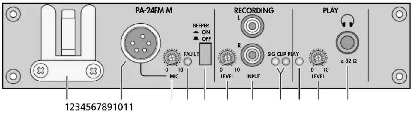
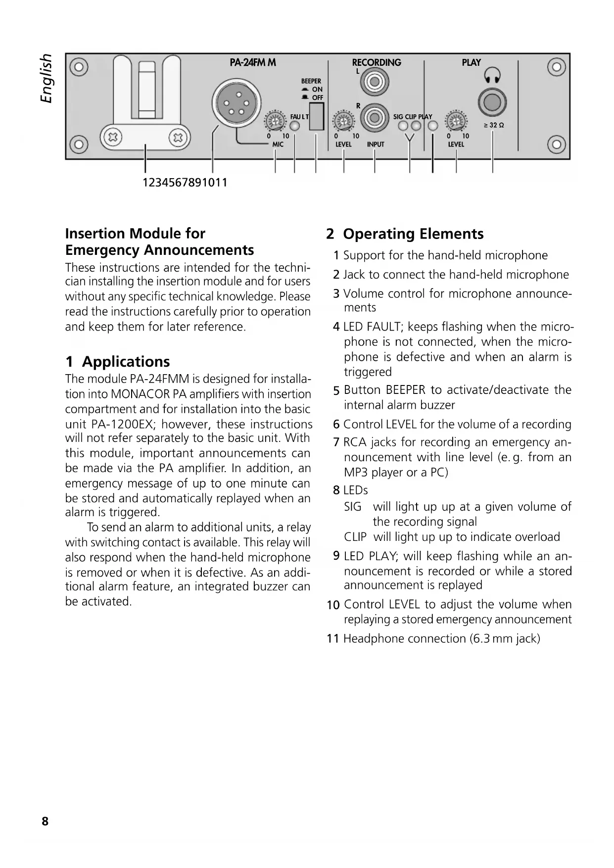
2 Operating Elements
1 Support for the hand-held microphone
2 Jack to connect the hand-held microphone
3 Volume control for microphone announcements
4 LED FAULT; keeps flashing when the microphone is not connected, when the microphone is defective and when an alarm is triggered
5 Button BEEPER to activate/deactivate the internal alarm buzzer
6 Control LEVEL for the volume of a recording
7 RCA jacks for recording an emergency announcement with line level (e.g. from an MP3 player or a PC)
8 LEDs
SIG will light up up at a given volume of the recording signal
CLIP will light up up to indicate overload
9 LED PLAY; will keep flashing while an announcement is recorded or while a stored announcement is replayed
10 Control LEVEL to adjust the volume when replaying a stored emergency announcement
11 Headphone connection (6.3 mm jack)
3 Safety Notes
The insertion module corresponds to all relevant directives of the EU and is therefore marked with €€
- The module must be installed by skilled personnel only.
- The module is suitable for indoor use only. Protect it against dripping water and splash water, high air humidity and heat (admissible ambient temperature range: 0–40°C).
- Immediately switch off the amplifier containing the module
- if the module or the amplifier is visibly damaged,
- if a defect might have occurred after the unit was dropped or suffered a similar accident,
- if malfunctions occur. In any case the module (with the amplifier) must be repaired by skilled personnel.
- For cleaning only use a dry, soft cloth; never use water or chemicals.
- No guarantee claims for the module and no liability for any resulting personal damage or material damage will be accepted if the module is used for other purposes than originally intended, if it is not correctly installed or operated, or if it is not repaired in an expert way.

If the module is to be put out of operation definitively, take it to a local recycling plant for a disposal which is not harmful to the environment.
4 Installing and Connecting the Module
WARNING

Always disconnect the mains plug of the amplifier from the socket before installing the module: Risk of electric shock!
1) Unscrew the housing cover of the amplifier.
2) On the front panel of the amplifier, unscrew the cover plate of the insertion compartment.
Remove the three-pole cable glued to the cover plate. Insert the module and fasten it. Then connect the cable to the pin connector AN07 AUDIO (see page 2). Thus, the module is supplied with -- 17 V and the audio signal is sent to the amplifier.
3) To install the connection plate provided (a), unscrew the corresponding cover plate on the rear of the amplifier or detach the corresponding cover plate. Insert the connection plate into the opening and fasten it with screws.
4) Connect the connection plate to the module according to the figure on page 2.
5) Before closing the housing cover of the amplifier, store an emergency message (chapter 5.1). A message can only be stored or deleted via the operating elements (b - f) on the PCB. This will prevent inadvertent deletion, for example.
6) For alarm triggering and thus for automatic replay of the stored emergency message, connect a corresponding alarm contact (normally open contact) to the alarm input E / M of the connection plate (a).
7) The relay contacts FAULT MONITOR of the connection plate allow to connect additional units for alarm transmission. The power rating of the relay contacts is 1 A at =24V or \~120V.
8) If a 24 V operating voltage is required, e. g. for an additional alarm relay, this voltage can be picked off at the terminals "24 V---" of the connection plate. The power rating is 40 mA. However, this 24 V voltage will only be applied during an alarm. (The alarm contact connected to the terminals E / M must be closed.)

text_image
PA-24FM M BEEPER ON OFF FAU LT 0 10 MIC RECORDING L R 0 10 LEVEL INPUT SIG CLIP PLAY 0 10 LEVEL PLAY ≥ 32 Ω 12345678910119) Connect the hand-held microphone to the jack MIC (2) and put it on its support (1).
When the microphone is removed or when it is defective, the internal alarm relay will respond. In addition, the alarm buzzer will sound when the button BEEPER (5) is engaged.
5 Operation
Switch on the amplifier; thus, the module PA-24FMM is also switched on.
The red LED LD5 on the PCB will light up as soon as the module is supplied with operating voltage from the amplifier. When the talk button of the microphone is pressed, the LED will be extinguished.
Important: The settings described in chapters 5.1–5.3 can only be made when the amplifier is open and should only be made by the installer!
5.1 Deleting and storing an emergency message
-
An emergency message can directly be recorded via the hand-held microphone.
-
Alternatively, a prepared message (e.g. from a PC or MP3 player) can be sent to the RCA jacks INPUT (7).
Important: Always disconnect the microphone from the PA-24FMM for this step; otherwise, the microphone will also pick up ambient noise, even if the talk button of the microphone is not pressed.
1) Set the switch AUTO/MANU (c) to the position MANU.
3) Disengage the button BEEPER (5) to deactivate the alarm buzzer for the next operating step.
4) Short-circuit the contacts E/M of the connection plate (a) to simulate an alarm. The LED FAULT (4) starts flashing. This is the only way to delete an existing message and to store a new message!
5) To delete an existing message, if necessary: Keep the button ERASE (e) pressed until the LED OPERATING on the PCB is extinguished. The LED PLAY (9) keeps flashing while the message is deleted.
6) Before starting the recording, make an announcement via the microphone or replay the prepared message to control the level. Use a screwdriver to set the control LEVEL (6) in the section RECORDING to a position where the red LED CLIP (8) will not light up yet. As a check, the green LED SIG will light up at a given volume.
7) To start recording, press the button REC (f). At the end of the announcement, press the button REC once again to stop recording. While the message is recorded, both the red LED OPERATING on the PCB and the green LED PLAY (9) will light up.
5.2 Replaying an emergency message as a check
1) Keep the contacts E / M short-circuited.
2) Set the switch REC / PLAY (d) to the position PLAY. Leave the switch AUTO / MANU still in the position MANU.
3) To start the replay, press the button PLAY (b). While the message is replayed, the LED PLAY (9) keeps flashing.
4) The message is reproduced via the PA system. Use the control LEVEL (10) in the section PLAY to adjust the volume of the message.
When headphones are connected to the jack Ⓞ(11), the message will only be reproduced via the headphones.
5.3 Settings for automatic start of a message
1) Remove the short circuit of the contacts E/M: The LED FAULT stops flashing.
2) Set the switch AUTO / MAN (c) to the position AUTO and the switch REC / PLAY (d) to the position PLAY.
3) To activate the internal alarm buzzer when an alarm is triggered, engage the button BEEPER (5).
4) For a functional test, short-circuit the contacts E / M once again or trigger an alarm via the alarm contact connected:
- The LED FAULT starts flashing and the alarm relay will respond.
- Before the emergency message is reproduced, a siren will sound for approx. 12 seconds.
- After the siren sound, the message will be continuously repeated until the alarm contact opens. Use the control LEVEL (10) to adjust the volume of the message.
5.4 Announcements via the hand-held microphone
Remove the microphone from its support, keep the talk button pressed to make an announcement and use the control MIC (3) to adjust the volume.
6 Specifications
Inputs
Mic: 2.5 mV, 600 Ω, unbal.
Line: 250 mV, 10 kΩ, unbal.
Outputs
Audio: 775mV, 600Ω
Headphones: ..... 24 mW, ≥ 32 Ω
Frequency range
Mic: 300–5400 Hz
Line: 100–5400 Hz
Storage medium for emergency announcement
Type: . . . . . . . . . non-volatile memory without back-up battery
Recording capacity: . 60 seconds
Data retention: ..... 100 years (typical)
Recording cycles: ... 100 000 (typical)
Alarm relay
Switch type: ..... selector switch (NO/NC)
Power rating: ..... 1 A, == 24 V/\~120 V
Power supply: ..... == 17V, 185 mA via amplifier
Ambient temperature: 0–40°C
Dimensions: 195×40×177mm (W × H × D)
Weight: 600 g
Subject to technical modification.