
XLF74 - Fireplace DIMPLEX - Free user manual and instructions
Find the device manual for free XLF74 DIMPLEX in PDF.
| Product Type | Electric fireplace insert |
| Brand | Dimplex |
| Model | XLF74 |
| Dimensions (W x H) | 189.7 cm x 40.6 cm |
| Weight (approx.) | 30 kg |
| Power supply | 230-240 V, 13 A, 50/60 Hz |
| Nominal heating power | 1.6 kW |
| Technology | Comfort$aver™: automatic adjustment of power and fan speed |
| Controls | Touch panel on the unit and infrared remote control |
| Flame effects | Yes, with multiple color themes and adjustable brightness |
| Heating modes | Normal, Eco (reduced power), Boost (full power up to 20 min) |
| Temperature range | 5 °C to 37 °C (41 °F to 99 °F) |
| Timer | Programmable sleep timer from 30 min to 8 h |
| Installation options | Partial recess, flush, or interior (max depth 12 mm) |
| Recommended installation height | 76.2 to 102 cm from floor (optimal flame angle) |
| Safety | Thermal circuit breaker, automatic shutoff in case of overheating, do not cover |
| Glass cleaning | Dry or damp lint-free cloth, no abrasive cleaners |
| Remote control battery | CR2032 (long life) or CR2025 |
| Warranty | 1 year |
| Included accessories | Suction cup, hex key, bubble level, fixing screws, mounting bracket |
| Repairability | Call a qualified technician; spare parts available via customer service |
| Recycling | Do not dispose with household waste; take to an approved recycling center |
Frequently Asked Questions - XLF74 DIMPLEX
User questions about XLF74 DIMPLEX
0 question about this device. Answer the ones you know or ask your own.
Ask a new question about this device
Download the instructions for your Fireplace in PDF format for free! Find your manual XLF74 - DIMPLEX and take your electronic device back in hand. On this page are published all the documents necessary for the use of your device. XLF74 by DIMPLEX.
USER MANUAL XLF74 DIMPLEX
Better solutions through innovation
text_image
Owner's ManualModel's
Ignite 50" / XLF50-EU
Ignite 60" / XLF60-EU
Ignite 74" / XLF74-EU
Ignite 100" / XLF100-EU
EN ENL
FR
RO
IT P L ES
EN : This product is only suitable for well insulated rooms or occasional use. DE : Dieses Produkt ist nur für gut isolierte Bereiche oder gelegentliche Verwendung geeignet. FR : Ce produit convient uniquement à des endroits bien isolés ou pour un usage occasionnel. IT : Questo prodotto è adatto solo per spazi ben isolati o per uso occasionale. ES : Este producto sólo es adecuado para espacios bien aislados o un uso ocasional. NL : Dit product is uitsluitend geschikt voor goed geïsoleerde ruimten of voor sporadisch gebruik. PL : Produkt ten jest odpowiedni wyłącznie do dobrze odizolowanych miejsc lub do okazjonalnego użytku. NO : Dette produktet egner seg kun for godt isolerte rom eller sporadisk bruk. RO : Acest produs este adecvat exclusiv spațiilor bine ventilate sau utilizării ocazionale. CZ : Tento výrobek je vhodný pouze do dobře izolovaných prostor nebo k příležitostnému použití. DK : Dette produkt er kun egnet til velisolerede rum eller lejlighedsvis brug. PT : Este produto somente é adequado para espaços bem isolados ou uso ocasional. SE : Denna produkt är endast avsedd för välisolerade utrymmen eller tillfällig användning. FI : Tämä tuote soveltuu ainoastaan hyvin eristettyihin tiloihin tai satunnaiseen käyttöön. SK : Tento výrobok je vhodný len pre dobre izolované priestory alebo na občasné použitie. SI : Ta izdelek je primeren le za dobro izolirane prostore ali za občasno uporabo. HR : Ovaj proizvod je pogodan samo za dobro izolirane prostore ili povremenu upotrebu. HU : Ez a termék csak jól szigetelt terekhez vagy eseti használatra alkalmas. SV : Denna produkt är endast lämplig för användning i väl isolerade utrymmen eller enstaka användning.

Table of Contents
i Welcome & Congratulations 3
IMPORTANT INSTRUCTIONS .... 4
Quick Reference Guide 6
Fireplace Installation 7
Operation.... 11
Maintenance 15
Always use a qualified technician or service agency to repair this fireplace.
! NOTE: Procedures and techniques that are considered important enough to emphasize.
CAUTION: Procedures and techniques which, if not carefully followed, will result in damage to the equipment.
WARNING: Procedures and techniques which, if not carefully followed, will expose the user to the risk of fire, serious injury, or death.

Welcome & Congratulations
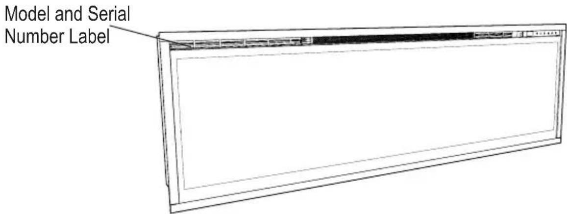
Thank you and congratulations for purchasing an electric fireplace from Dimplex. Please take note of the location of the Model & Serial for this product it is important to be able to locate it in the event of requiring technical support.
text_image
Model and Serial Number LabelPlease carefully read and save these instructions.
CAUTION: Read all instructions and warnings carefully before starting installation. Failure to follow these instructions may result in a possible electric shock, fire hazard and will void the warranty.

IMPORTANT INSTRUCTIONS
Important Safety Advice
When using electrical appliances, basic precautions should be followed to reduce the risk of fire, electric shock, and injury to persons, including the following:
If the appliance is damaged, check immediately with the supplier before installation and operation.
Do not use this appliance in the immediate surroundings of a bath, shower or swimming pool.
Do not use outdoors.
This appliance must not be located immediately above or below a fixed socket outlet or connection box.
WARNING: The appliance carries the Warning Symbol indicating that it must not be covered or has a Do not cover label. Do not cover or obstruct in any way the heat outlet grille located at the top of the appliance overheating will result if the appliance is accidentally covered. Do not place material or garments on the appliance, or obstruct the air circulation around the appliance, for instance by curtains or furniture, as this could cause overheating and a fire risk.
In the event of a fault unplug the heater. Unplug the appliance when not required for long periods. The supply cord must be placed on the right hand side of the heater away from the heat outlet underneath the appliance.
Although this appliance complies with safety standards, we do not recommend its use on deep pile carpets or on long hair type of rugs.
This appliance can be used by children aged from 8 years and above and persons with reduced physical, sensory or mental capabilities or lack of experience and knowledge if they have been given supervision or instruction concerning use of the appliance in a safe way and understand the hazards involved. Children shall not play with the appliance. Cleaning and user maintenance shall not be made by children

IMPORTANT INSTRUCTIONS
without supervision.
Children of less than 3 years should be kept away unless continuously supervised. Children aged from 3 years and less than 8 years shall only switch on/off the appliance provided that it has been placed or installed in its intended normal operating position and they have been given supervision or instruction concerning use of the appliance in a safe way and understanding the hazards involved. Children aged from 3 years and less than 8 years shall not plug in, regulate and clean the appliance or perform user maintaince.
The appliance must be positioned so that the plug is accessible.
If the supply cord is damaged it must be replaced by the manufacturer or service agent or similarly qualified person in order to avoid a hazard.
CAUTION: In order to avoid a hazard due to inadvertent resetting of the thermal cut-out, this appliance must not be supplied through an external switching device, such as a timer, or connected to a circuit that is regularly switched on and off by the utility.
CAUTION - Some parts of this product can become very hot and cause burns. Particular attention has to be given where children and vulnerable people are present.

text_image
Warning symbol for electrical hazard, indicating a current drop with a lightning bolt symbol inside a triangleCAUTION
RISK OF ELECTRIC SHOCK
DO NOT OPEN
NO USER-SERVICABLE PARTS INSIDE
SAVE THESE INSTRUCTIONS

text_image
Warning symbol with exclamation mark inside triangle, commonly used for safety alerts
Quick Reference Guide
- The electrical information regarding your electric fireplace can be found on the rating label located on the top of the unit.
- If you have any technical questions or concerns
regarding the operation of your electric fireplace, or require service contact the relavent customer service as listed on your warranty card.
- For dimensions of your fireplace, refer to Figure 1.
Technical Information
Model No: XLF50-EU, XLF60-EU, XLF74-EU, XLF100-EU
Heat Output 230V 240V
| Nominal Heat Output P | Nom | 1.6 - | 1 | 6 kW | |
| Minimum Heat Output | Pmin | - | - | - | kW |
| Maximum Continuous Heat Output Pmax,c | 1.6 - | 1 | 6 kW | ||
Auxiliary Electricity Consumption
| In Standby mode | eI_SB | 0.47 | - | 0.49 | W |
with electronic room temperature control
Figure 1

text_image
XLF50 50.31 in [1278 mm] XLF60 60.31 in [1532 mm] XLF74 74.31 in [1887 mm] XLF100 100.31 in [2548 mm] [16.49 in 419 mm] XLF50 51.41 in [1306 mm] XLF60 61.41 in [1560 mm] XLF74 75.41 in [1941 mm] XLF100 101.41 in [2576 mm] [15.00 in. 381 mm [15.82 in. 402 mm] [4.34 in. 110 mm] [5.79 in. 47 mm]
Fireplace Installation
CAUTION: Ensure installation does not allow fireplace to be in direct contact with building vapor barrier or insulation and meets all local building code.
! NOTE: A dedicated, properly fused 13 Amp circuit is required, rated for the appropriate voltage (230-240V).
WARNING: Construction and wiring must comply with local building codes and other applicable regulations to reduce the risk of fire, electric shock and injury to persons.
WARNING: To reduce the risk of fire, electric shock or injury to persons, always use a licensed electrician.
WARNING: To reduce the risk of fire, do not store or use gasoline or other flammable vapors or liquids in the vicinity of the heater.
-
Select a location that is not susceptible to moisture and is away from drapes, furniture and high traffic.
-
Unpack the fireplace and hardware from the box.
! NOTE: Leave the front glass and partially reflective glass, safely, in the box until the time you
are ready to install it.
- Store the fireplace in a safe, dry and dust free location until you are ready to install the fireplace.
Installation
CAUTION: Two people will be required for various steps of this procedure.
This design of this unit allows three options for installation: partial recess, flush mounted or sub-surface mounted.
CAUTION: Sub-surface
mounting should be limited to 12 in. (12 mm) to ensure adequate air flow of heated air out of the firebox area.
- Prepare a wall with a framed opening of 16 in. (40.6 cm) high,
• XLF50 - 50 % in. (128.7 cm)
• XLF60 - 60 % in. (154.0 cm)
• XLF74 - 74 % in. (189.7 cm)
- XLF100 - 100 % in. (255.7 cm) wide, with a bottom sill that is a minimum of 4 in. (10.2 cm) deep. The sill can be constructed to support the front of the unit to allow the power supply wires to easily

Fireplace Installation
be run behind or flush with the back of the unit and a pass thru hole drilled for electrical wire routing.
! NOTE: It is recommended that the bottom of the unit be mounted between 30 in. (76.2 cm) and 40 in. (102 cm) from the ground to maintain an optimized viewing angle of the flame.
WARNING: Do not attempt to wire your own new circuits. To reduce the risk of fire, electric shock or injury to persons, always use a licensed electrician.
WARNING: Ensure that the circuit on which the fireplace is to be installed has the power cut off at the service panel until installation is complete.
- The unit is provided with an installed 34 in. (2.0 cm) trim.
Depending on the installation, this trim can be removed by removing the securing screws and the 4 trim pieces.
-
Lift fireplace, from the bottom and the handles located on the back, and insert into opening to the desired depth.
-
Using a bubble level (supplied) ensure that the fireplace is level within the framing. Adjust as required.
-
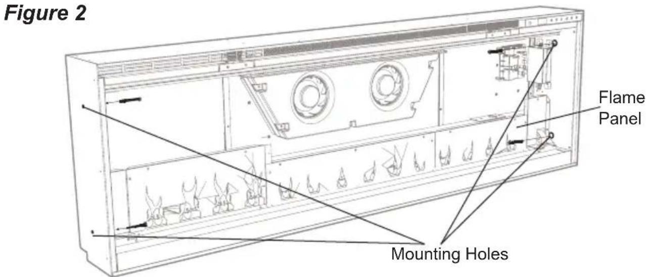
Drive four supplied mounting screws through the four mounting holes located on the inside surface of the fireplace chassis, into wall studs (Figure 2).
text_image
Figure 2 Flame Panel Mounting HolesFigure 3

text_image
Retaining Bracket Glass Openings Partially Reflective Glass Media TrayTo prevent electrical shock this unit is an electrical appliance that is NOT watertight and must be installed as to prevent water from entering unit. This must be installed away from showers, tubs, etc. Never locate fireplace where it may fall into a bathtub or other water container.
Final Assembly
-
Locate and remove the 12 screws securing the partially reflective glass bracket to the unit, along the top of the opening, and set bracket and screws aside.
-
Remove the provided suction cup from the inside cavity of the unit (only for XLF60, XLF74 and XLF100 units).
-
Before installation ensure that the front glass and the partially reflective glass are clean. Particles can be removed by dusting lightly with a clean dry cloth. To remove fingerprints or other marks, the glass can be cleaned with a damp cloth. Ensure that the glass has completely dried before installation.
-
Carefully secure the suction cup to the partially reflective glass, reflective side out, and place into the openings on either side of the unit.
-
Tip the glass into the unit and using the removed screws secure the glass into the unit with the provided bracket (Figure 3). Remove the suction cup.

Fireplace Installation
- Evenly space the large media in the media tray along the back of the media tray (for optimum media effect), then carefully pour and evenly distribute the smaller media into the Media Tray.
- Carefully place the front glass into the lip located at the bottom of the opening of the firebox.
- Tip the front glass into the unit and secure using the provided screws and Allen key. (Figure 4).
! NOTE: Ensure that the suction cup and Allen key are kept for any future maintenance or service.
Fixed Wiring
In some jurisdictions this appliance is supplied without a plug this is to comply with the local regulations. In such instances this appliance must be installed by a suitably qualified installer and the means for disconnection must be incorporated in the fixed wiring in accordance with the local wiring rules.
Figure 4

natural_image
Technical line drawing of a wall-mounted air conditioner unit with a close-up inset showing internal components (no text or symbols)General Operation
WARNING: This electric firebox must be properly installed before it is used.
This firebox operates with Comfort\$aver™ technology, which automatically adjusts the fan speed and heater wattage to safely and precisely match the requirements of the room based on the thermostat setting. The heater operates such that once the room reaches the set point, the fan and heater will continuously run at a low level, to maintain the desired room temperature. If the temperature in the room rises significantly, i.e. sun coming through a window or a central furnace turns on, the heater will turn off and periodically turn back on to circulate the air around the unit, until the room temperature drops and requires the heater to be constantly on again.
! NOTE: The unit is designed so that the fan will run continuously while the heater is on.
! NOTE: The element retains heat after shutdown, there is a built in cool down period of 2 minute before the fan shuts off completely, when the heat function is turned Off.
Remote Operation
The fireplace is supplied with an IR multi-function remote control.
! NOTE: To operate correctly, the remote control must be pointed towards the front of the unit.
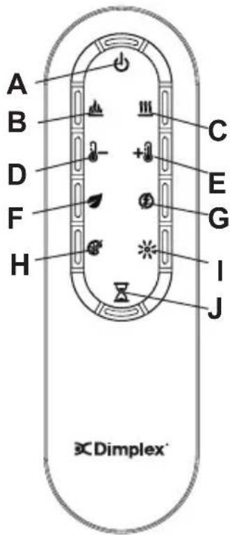
Controls
The unit can be controlled by either the manual controls which are located on the upper right of the fireplace or the remote (Figure 5 & 6).
A. Standby
Turns the unit On and Off.
→ Activated by pressing the Standby button on the remote or the unit.
- The unit will turn On with the same functions that it was set to when it was turned Off and the intake temperature will be indicated on the Display.
! NOTE: When any button is pressed on the unit the intake temperature will be displayed on the Display for 7 seconds.
B. Flame Effects
Turns the Flame Effect On and Off.
→ Activated by pressing the button on the remote.

Operation

text_image
Figure 5 C J Display A H IC. ≡ Heat ON/OFF
Turns the heater On and Off.
→ Activated by pressing the button on the remote.
- Indicated by the 🎄icon and the setpoint temperature will flash on the display, then the intake temperature will be displayed before turning off.
! NOTE: After the heater is switched off, there is a 2 minute fan delay, where the fan will continue running before turning off.
! NOTE: The unit can be operated in Heat Only Mode. When the unit is only running with the heater, the !!! icon will continuously be displayed on the Display.
! NOTE: The heater may emit a slight, harmless odor when first used. This odor is a normal condition caused by initial heating
Figure 6
text_image
A B C D E F G H I J ×Dimplex*of internal heater parts and will not occur again.
D — Temperature Down
Decreases the temperature setting.
→ Adjusted by repeatedly pressing the corresponding button on the remote.*
- Indicated by setpoint temperature on the Display decreasing and the speed of the fan decreasing to reduce the amount of heat being projected into the room.**
E. +Temperature Up
Increases the temperature setting.

Operation
→ Adjusted by repeatedly pressing the corresponding button on the remote.*
- Indicated by the setpoint on the Display increasing and the speed of the fan increasing to increase the amount of heat being projected into the room.
* The first time the button is pressed the current temperature set point will be displayed for 2 seconds.
** The temperature can be adjusted from 5 °C to 37 °C (41 °F to 99 °F).
! NOTE: Holding the ∴ and
the •• buttons down for two seconds, on the unit, will change the temperature scale from °C to °F, or vice versa.
F. Eco Operation
Runs the heater in a reduced wattage range when activated.
→ Adjusted by pressing the corresponding button on the remote when the heater is on.
- Indicated by the Display and a reduced fan speed.
G. Heat Boost
Turns the Heater Boost On and Off. Runs the unit at the full rated wattage.
→ Activated and adjusted by repeatedly pressing the corresponding button on the remote.
- Indicated by the heater running at full heat, for a user set amount of time, to quickly heat up a cold room/space. The Heat Boost can be set for a maximum of 20 minutes, in 5 minute increments.
Disable Heat
If desired, depending on the season, the heater on the unit can be disabled. The function of the remaining controls will continue to function as outlined in this manual.
Pressing the • and •• buttons on the unit at the same time and holding for 2 seconds will disable and enable the heater.
! NOTE: When the heater has been disabled and any of the heat related functions are used, the Display will indicate "---".
H. Color Themes
Different presets of lighting color combinations are available in the unit.
→ Changed by repeatedly pressing the corresponding button on the remote or the unit.

Operation
- Cycles through the different preset light settings of the unit, this includes different combinations of colors of the flame base and media lighting.
! NOTE: Two of the themes in the cycle are a prism where the unit cycles through a variety of colors. Pressing the stops the cycling and holds the unit on the preferred color, indicated by a solid circle. When the unit is on prism, and is cycling through the colors, a rotating circle will be displayed.

Brightness
Changes the Brightness of the lights in the unit.
→ Adjusted by repeatedly pressing the corresponding button on the remote or the unit.
- Indicated by the second digit on the Display changing to show: "H" (high), and "L" (low).
J. Sleep Timer
The Sleep Timer can be set to automatically shut off the fireplace after a preset time (from 30 minutes to 8 hours).
→ To set the timer press the timer button on the remote,
repeatedly, until the desired time is displayed.
- The Display will display the different times as it is adjusted. Once the timer has begun, pressing the button will display the time remaining before the unit turns Off.
! NOTE: The Sleep Timer can be cancelled at any time by pressing the 📄 button repeatedly until the sleep timer displays nothing.
Resetting the Temperature Cutoff Switch
Should the heater overheat, an automatic cut out will turn the whole unit off and it will not come back on without being reset. If the button on the unit is pressed, Er2 will be displayed on the unit. It can be reset by turning the unit off at the main disconnect panel and waiting 5 minutes before turning the unit back on.
CAUTION: If you need to continuously reset the heater, turn the unit off at the main disconnect panel and call technical support.

Operation

Maintenance
Remote Control Battery Replacement
To replace the Battery:
- Slide battery cover open on the remote control.
-
Correctly install one 3 Volt (CR2032 [longer life] or CR2025) Battery in the battery holder.
-
Close the battery cover.
Battery must be recycled or disposed of properly. Check with your Local Authority or Retailer for recycling advice in your area.
WARNING: Disconnect power and allow heater to cool before attempting any maintenance or cleaning to reduce the risk of fire, electric shock or damage to persons.
! NOTE: The fireplace should not be operated with an accumulation of dust or dirt on or in the unit, as this can cause a build up of heat and eventual damage. For this reason the heater must be inspected regularly, depending upon conditions and at a minimum yearly intervals.
Partially Reflective Glass Cleaning
The partially reflective glass is cleaned in the factory during the assembly operation. During shipment, installation, handling, etc., the partially reflective glass may collect dust particles; these can be removed by dusting lightly with a clean dry cloth.
To remove fingerprints or other marks, the partially reflective glass can be cleaned with a damp cloth. The partially reflective glass should be completely dried with a lint free cloth to prevent water spots. To prevent scratching, do not use abrasive cleaners.
Fireplace Surface Cleaning
Use only a damp cloth to clean painted surfaces of the fireplace. Do not use abrasive cleaners.
Recycling
At the end of the electrical products useful life it should not be disposed of with household waste. Please recycle where facilities exist. Check with your Local Authority or retailer for recycling advice in your country.

After Sales Service
Your product is guaranteed for one year from the date of purchase.
Within this period, we undertake to repair or exchange this product free of charge (excluding lamps & subject to availability) provided it has been installed and operated in accordance with these instructions.
Your rights under this guarantee are additional to your statutory rights, which in turn are not affected by this guarantee.
Should you require after sales service you should contact our customer services the contact number is located on your warranty card. It would assist us if you can quote the model number, series, date of purchase, and nature of the fault at the time of your call. The customer services help desk will also be able to advise you should you need to purchase any spares.
Please do not return a faulty product to us in the first instance as this may result in loss or damage and delay in providing you with a satisfactory service.
Please retain your receipt as proof of purchase.
text_image
Warning symbol with lightning bolt inside triangle, indicating electrical hazard or current warningVORSICHT
STROMSCHLAGGEFAHR
NICHT ÖFFNEN
ES BEFINDEN SICH KEINE TEILE IM GERÄT, DIE VOM
text_image
XLF50 50.31 in [1278 mm] XLF60 60.31 in [1532 mm] XLF74 74.31 in [1887 mm] XLF100 100.31 in [2548 mm] [16.49 in ] 419 mm XLF50 51.41 in [1306 mm] XLF60 61.41 in [1560 mm] XLF74 75.41 in [1941 mm] XLF100 101.41 in [2576 mm] [15.00 in ] 381 mm [15.82 in ] 402 mm [4.34 in ] 110 mm [5.79 in ] 47 mm
Montage des Kamins
natural_image
Technical line drawing of a wall-mounted air conditioner unit with a close-up inset showing internal components (no text or symbols)Allgemeiner Betrieb
text_image
A B C D E F G H I J ×Dimplex*text_image
Warning symbol with exclamation mark inside triangle, commonly used to indicate caution or hazardtext_image
XLF50 50.31 in [1278 mm] XLF60 60.31 in [1532 mm] XLF74 74.31 in [1887 mm] XLF100 100.31 in [2548 mm] 16.49 in 419 mm XLF50 51.41 in [1306 mm] XLF60 61.41 in [1560 mm] XLF74 75.41 in [1941 mm] XLF100 101.41 in [2576 mm] [15.00 in. 381 mm [15.82 in. 402 mm] [4.34 in. 110 mm] [5.79 in. 47 mm]
natural_image
Technical line drawing of a wall-mounted air conditioner unit with a close-up inset showing internal components (no text or symbols)Vaste bedrading
text_image
A B C D E F G H I J ×Dimplex*C. III Warmte AAn/UIT
text_image
Warning symbol with exclamation mark inside triangle, commonly used to indicate caution or hazardCONSERVEZ CES INSTRUCTIONS

text_image
XLF50 50.31 in [1278 mm] XLF60 60.31 in [1532 mm] XLF74 74.31 in [1887 mm] XLF100 100.31 in [2548 mm] [16.49 in ] 419 mm XLF50 51.41 in [1306 mm] XLF60 61.41 in [1560 mm] XLF74 75.41 in [1941 mm] XLF100 101.41 in [2576 mm] [15.00 in ] 381 mm [15.82 in ] 402 mm [4.34 in ] 110 mm [5.79 in ] 147 mm
natural_image
Technical line drawing of a rectangular electronic device with a close-up inset showing internal components (no text or symbols)text_image
Figure 5 C J Afficher A H IC. III Activation/désactivation de la chaleur
text_image
A B C D E F G H I J ×Dimplex*text_image
Warning symbol depicting a lightning bolt inside a triangle, indicating electrical hazard or current warning.ATENTIE
PERICOL DE ELECTROCUTARE
NU DESCHIDETI
ÎN INTERIOR NU EXISTĂ PIESE CE
POT FI REPARATE DE UTILIZATOR
text_image
Warning symbol with exclamation mark inside triangle, commonly used to indicate caution or hazardPĂSTRATI ACESTE INSTRUCTIUNI

text_image
XLF50 50.31 in [1278 mm] XLF60 60.31 in [1532 mm] XLF74 74.31 in [1887 mm] XLF100 100.31 in [2548 mm] [16.49 in ] 419 mm XLF50 51.41 in [1306 mm] XLF60 61.41 in [1560 mm] XLF74 75.41 in [1941 mm] XLF100 101.41 in [2576 mm] [15.00 in ] 381 mm [15.82 in ] 402 mm [4.34 in ] 110 mm [5.79 in ] 147 mm
Instalarea şemineului
natural_image
Line drawing of a wall-mounted air conditioner unit with a close-up inset showing the cable attachment detail (no text or symbols)Operarea generală
text_image
A B C D E F G H I J ×Dimplex*natural_image
Line drawing of a rectangular frame with a blank center and top border (no text or symbols)text_image
Warning symbol depicting a lightning bolt inside a triangle, indicating electrical hazard or current warning.ATTENZIONE
PERICOLO DI SCOSSE ELETTRICHE
NON APRIRE
ALL'INTERNO DELL'APPARECCHIATURA
NON SONO PRESENTI PARTI RIPARABILI
DALL'UTENTE

text_image
Warning symbol with exclamation mark inside triangle, commonly used to indicate caution or hazardCONSERVARE QUESTE ISTRUZIONI

Figura 1

XLF50 51.41 in [1306 mm]
XLF60 61.41 in [1560 mm]
XLF74 75.41 in [1941 mm]
XLF100 101.41 in [2576 mm]

natural_image
Technical line drawing of a wall-mounted air conditioner unit with a close-up inset showing internal components (no text or symbols)text_image
Figura 5 C J Display A H Itext_image
A B C D E F G H I J ×Dimplex®text_image
Warning symbol depicting a lightning bolt inside a triangle, indicating electrical hazard or current warning.PRZESTROGA
RYZYKO PORAŻENIA PRADEM ELEKTRYCZNYM
NIE OTWIERAĆ
URZĄDZENIE NIE POSIADA CZEŚCI
WYMAGAJĄCYCH OBSŁUGI UŻYTKOWNIKA
text_image
Warning symbol with exclamation mark inside triangle, commonly used to indicate caution or hazardtext_image
XLF50 50.31 in [1278 mm] XLF60 60.31 in [1532 mm] XLF74 74.31 in [1887 mm] XLF100 100.31 in [2548 mm] 16.49 in 419 mm XLF50 51.41 in [1306 mm] XLF60 61.41 in [1560 mm] XLF74 75.41 in [1941 mm] XLF100 101.41 in [2576 mm] 15.00 in. 381 mm [15.82 in. 402 mm] [4.34 in. 110 mm] [5.79 in. 147 mm]natural_image
Technical line drawing of a wall-mounted air conditioner unit with a close-up inset showing the cable attachment detail (no text or symbols)text_image
A B C D E F G H I J ×Dimplex*C. Ⅲ WŁ/WYŁ grzejnika
natural_image
Line drawing of a rectangular frame with a blank center and top border (no text or symbols)text_image
Warning symbol for electrical hazard, showing a lightning bolt inside a triangleRIESGO DE DESCARGA ELÉCTRICA
NO ABRIR
EN EL INTERIOR NO HAY PIEZAS
text_image
Warning symbol with exclamation mark inside triangle, commonly used to indicate caution or hazardGUARDAR ESTAS INSTRUCCIONES

text_image
XLF50 50.31 in [1278 mm] XLF60 60.31 in [1532 mm] XLF74 74.31 in [1887 mm] XLF100 100.31 in [2548 mm] [16.49 in ] 419 mm XLF50 51.41 in [1306 mm] XLF60 61.41 in [1560 mm] XLF74 75.41 in [1941 mm] XLF100 101.41 in [2576 mm] [15.00 in ] 381 mm [15.82 in ] 402 mm [4.34 in ] 110 mm [5.79 in ] 47 mm