
Prism BLF3451-AU - Fireplace DIMPLEX - Free user manual and instructions
Find the device manual for free Prism BLF3451-AU DIMPLEX in PDF.


| Product Type | Electric Fireplace |
| Model | Prism BLF3451-AU |
| Brand | Dimplex |
| Width | 34.5 inches (876 mm) |
| Height | 22.5 inches (572 mm) |
| Depth | 7.5 inches (190 mm) |
| Weight | Approximately 12.5 kg |
| Power Supply | 120 V ~ 60 Hz |
| Rated Power Consumption | 1500 W |
| Heater Type | Fan-forced |
| Flame Effect | LED with multiple color options |
| Control Method | Remote control and touch panel |
| Installation Type | Built-in or wall-mounted |
| Safety Features | Overheat protection, cool-touch glass |
| Maintenance | Clean glass with soft cloth; vacuum vents |
| Compatible with Smart Home | No (standalone unit) |
| Warranty | 1 year limited |
Frequently Asked Questions - Prism BLF3451-AU DIMPLEX
User questions about Prism BLF3451-AU DIMPLEX
0 question about this device. Answer the ones you know or ask your own.
Ask a new question about this device
Download the instructions for your Fireplace in PDF format for free! Find your manual Prism BLF3451-AU - DIMPLEX and take your electronic device back in hand. On this page are published all the documents necessary for the use of your device. Prism BLF3451-AU by DIMPLEX.
USER MANUAL Prism BLF3451-AU DIMPLEX
natural_image
Technical line drawing of a rectangular electronic device with internal slots and mounting brackets (no text or symbols)EN
IMPORTANT SAFETY INFORMATION: Always read this manual first before attempting to install or use this fireplace. For your safety, always comply with all warnings and safety instructions contained in this manual to prevent personal injury or property damage.

Table of Contents
i Welcome & Congratulations 3
IMPORTANT INSTRUCTIONS 4
Quick Reference Guide ..... 7
Fireplace Installation 8
Site Selection 8
Surface Installation 9
In-wall Recessed Installation - 100mm Deep 10
Flush Mounted Installation - 200mm Deep 11
Front Glass Installation 13
Operation 15
Maintenance 19
Contact Details 19
Always use a qualified technician or service agency to repair this fireplace.
! NOTE: Procedures and techniques that are considered important enough to emphasize.
CAUTION: Procedures and techniques which, if not carefully followed, will result in damage to the equipment.
WARNING: Procedures and techniques which, if not carefully followed, will expose the user to the risk of fire, serious injury, or death.

Welcome & Congratulations
Thank you and congratulations for choosing to purchase an electric fireplace from Dimplex, the world leader in electric fireplaces.
Please carefully read and save these instructions.

CAUTION: Read all instructions and warnings carefully before starting installation. Failure to follow these instructions may result in a possible electric shock, fire hazard and will void the warranty.
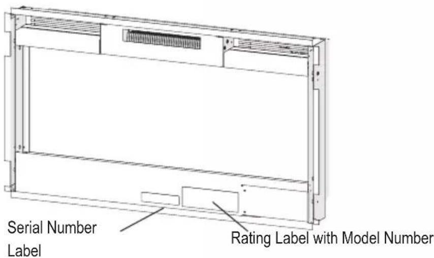
Please record your model and serial numbers below for future reference: model and serial numbers can be found on the Model and Serial Number Label of your fireplace.

NO NEED TO RETURN TO THE STORE
Questions With the Assembly? Require Parts Information?
Product Under Manufacturer's Warranty?

Call 1300 556 816
Please have your model number and product serial number ready. (See below)

IMPORTANT SAFETY INSTRUCTIONS
Read all instructions before using this appliance.
When using electrical appliances, basic precautions should always be followed to reduce the risk of fire, electrical shock and injury to persons, including the following:
- If the appliance is damaged, check with the supplier before installation and operation.
- Do not use outdoors.
- Do not use in the immediate surroundings of a bath, shower or swimming pool.
- Do not locate the appliance immediately below a fixed socket outlet or connection box.
- This appliance is not intended for use by persons (including children) with reduced physical, sensory or mental capabilities, or lack of experience and knowledge, unless they have been given supervision or instruction concerning use of the appliance by a person responsible for their safety. Children should be supervised to ensure that they do not play with the appliance. Cleaning and user maintenance shall not be made by Children. Children should be supervised to ensure that they do not play with the appliance.
- Do not use this appliance in series with a thermal control, a program controller, a timer or any other device that switches on the heat automatically, since a fire risk exists when the appliance is accidentally covered or displaced.
- Ensure that furniture, curtains or other combustible material are positioned no closer than 1 metre from the

IMPORTANT SAFETY INSTRUCTIONS
appliance.
- In the event of a fault unplug the appliance.
- Unplug the appliance when not required for long periods.
- Although this appliance complies with safety standards, we do not recommend its use on deep pile carpets or on long hair type of rugs.
- The appliance must be positioned so that the plug is accessible.
- If the supply cord is damaged it must be replaced by the manufacturer or service agent or a similarly qualified person in order to avoid a hazard.
- Keep the supply cord away from the front of the appliance.
WARNING: In order to avoid overheating, do not cover the appliance. Do not place material or garments on the appliance, or obstruct the air circulation around the appliance, for instance by curtains or furniture, as this could cause overheating and a fire risk.
WARNING: In order to avoid a hazard due to inadvertent resetting of the thermal cut-out, this appliance must not be supplied through an external switching device, such as a timer, or connected to a circuit that is regularly switched on and off by the utility.
CAUTION: Some parts of this product can become very hot and cause burns. Particular attention has to be given where children and vulnerable people are present.

IMPORTANT SAFETY INSTRUCTIONS
It is necessary to allow disconnection of the appliance from the supply after installation. The disconnection can be achieved by having the plug accessible or by incorporating a switch in the fixed wiring in accordance with the wiring rules.
⚠ WARNING: The heater must not be used if the glass panels are damaged.
WARNING: KEEP BATTERIES OUT OF REACH OF CHILDREN
- Swallowing may lead to serious injury in as little as 2 hours or death, due to the chemical burns and potential perforation of the oesophagus.
- If you suspect your child has swallowed or inserted a button battery immediately call the 24-hour Poisons Information Centre on 13 11 26 (in Australia) or 0800 764 766 (in New Zealand) for fast, expert advice.
- Examine devices and make sure the battery compartment is correctly secured, e.g. that the screw or other mechanical fastener is tightened. Do not use if the compartment is not secure.
- Dispose of used button batteries immediately and safely. flat batteries can still be dangerous.

The heater carries the Warning Symbol [p y] indicating that it must not be covered SAVE THESE INSTRUCTIONS
① The electrical information regarding your electric fireplace can be found on the rating label located on the front of the unit, behind the glass.
Before installation, please record your fireplace's serial number below for future reference.
② If you have any technical questions or concerns regarding the operation of your electric fireplace, or require service contact customer service.
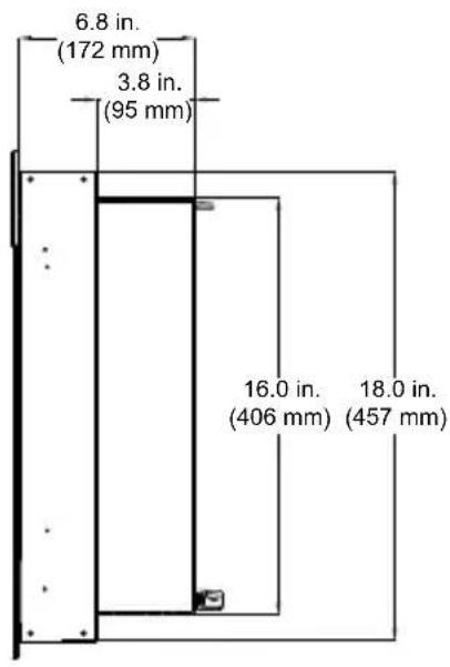
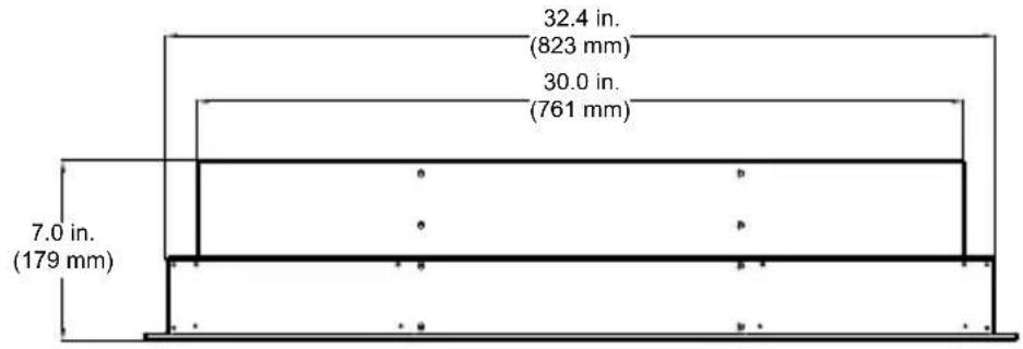
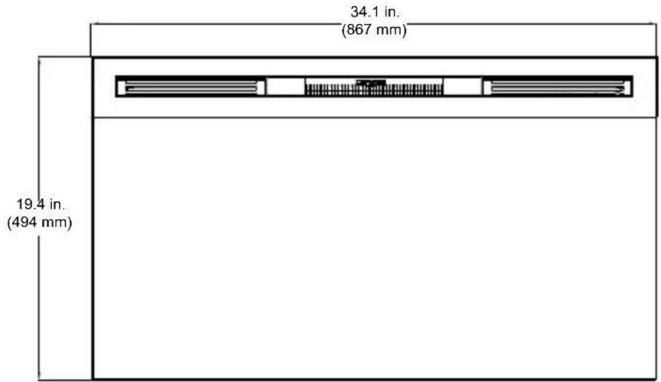
③ For dimensions of your fireplace, refer to Figure 1.
Figure 1
Site Selection
Review and consider all of the following conditions for installation:
- Dimensions of the unit: 870mm x 495mm
- Unit requires a minimum of three (3) wall studs in order to ensure a secure installation
Three possible installation methods:
• Installation method: Surface mount; In-wall Recessed; or Flush mount
• Hardwired or plug-in method

WARNING: Ensure the power cord is not installed so that it is pinched or against a sharp edge and ensure that the power cord is stored or secured to avoid tripping or snagging to reduce the risk of fire, electric shock or injury to persons.
Construction and electrical outlet wiring must comply with local building codes and other applicable regulations to reduce the risk of fire, electric shock and injury to persons.
-
Select a location that is not susceptible to moisture and is away from drapes, furniture and high traffic.
-
For ease of electrical hook up you may wish to locate the fireplace near an existing outlet (for plug-in convenience).
! NOTE 1: A 10 Amp, 230-240 Volt circuit is required. A dedicated circuit is preferred but not essential in all cases. A dedicated circuit will be required if, after installation, the circuit breaker trips or fuse blows on a regular basis when the heater is operating. Additional appliances on the same circuit may exceed the current rating of the circuit breaker.
-
Remove fireplace, front glass and hardware from box and remove all packaging materials before installation.
-
Store the fireplace in a safe, dry and dust free location until you are ready to install the fireplace.

Fireplace Installation
The fireplace is packaged with a three prong plug installed for plug-in convenience. Hard wiring the fireplace is also an option by removing the plug from the factory fitted cord and completing the wiring according to National and Local Electrical Codes.
The appliance must be fitted with means for disconnection from the supply mains having a contact separation in all poles that provide full disconnection under overvoltage category III conditions, and these means must be incorporated in the fixed wiring in accordance with the wiring rules.

WARNING: Do not attempt to wire your own new outlets or circuits. To reduce the risk of fire, electric shock or injury to persons, always use a licensed electrician.

WARNING: Ensure that the 3-Position Switch is set to the Off position ("O") and that the circuit on which the fireplace is to be installed has the power cut off at the service panel until installation is complete.
Surface Installation

CAUTION: Two people will be required for various steps of
this procedure.
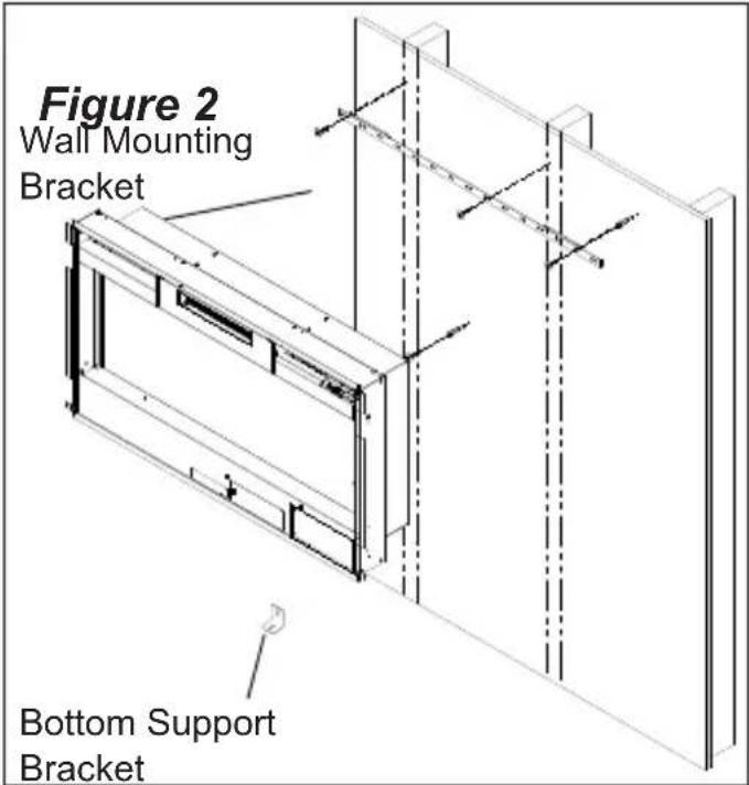
- Determine the mounting location of the unit so that the wall-mounting bracket can be installed into 3 wall studs.
! NOTE: It is recommended that the mounting bracket be installed 56 in. (1420mm) off of the ground to maintain an optimized viewing angle of the flame.
-
Hold the wall mounting bracket, with the bubble level on the top, on the wall so that the bubble on the level is centered between the two black lines.
-
Mark the 4 mounting screw locations, on the wall, ensuring that the wall bracket stays level. (Figure 2)
-
In locations where the screws

Fireplace Installation
Figure 3
natural_image
Technical line drawing of a flat-screen monitor mounted on a stand, with an inset showing a close-up of the screen (no text or symbols present)are being installed only into drywall, install the supplied wall anchors before installing the screw (predrill if required).
- Secure the wall bracket to the wall using the supplied 1 12 in. (38mm) mounting screws and washers into the wall and/or wall anchors.
- Install the bottom support bracket to the wall centered with the wall mounting bracket, using the appropriate mounting hardware, 13 34 " (350mm) below the wall mounting bracket. (Figure 2)
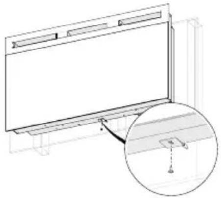
- Remove the center screw from the bottom of the fireplace. (Figure 3)
- Hang the fireplace from the bracket.
- Install the removed screw through the bottom support
bracket into the fireplace.
- Refer to Front Glass Installation section final installation procedures.
In-wall Recessed Installation - 100mm Deep

CAUTION: Two people may be required for various steps of this procedure.
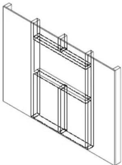
- Prepare a wall with a framed opening of 775mm wide x 420 mm high (Figure 4).
! NOTE: The sizing has allowed for 7mm around the fireplace insert for ease of installation. This fireplace does not require any additional venting. -
Choose your method of supplying power to the unit:
-
Plug in (you may run the power cord out of the framed wall opening to an existing outlet or install an outlet on a nearby wall stud within the wall).
- Hard wire the fireplace.
! NOTE: Hard wiring can be done by removing the plug from the factory fitted cord and completing the wiring according to National and Local Electrical Codes.

Fireplace Installation
The appliance must be fitted with means for disconnection from the supply mains having a contact separation in all poles that provide full disconnection under overvoltage category III conditions, and these means must be incorporated in the fixed wiring in accordance with the wiring rules.
WARNING: Do not attempt to wire your own new outlets or circuits. To reduce the risk of fire, electric shock or injury to persons, always use a licensed electrician.
Ensure that the 3-Position Switch is set to the Off position ("O") and that the circuit on which the fireplace is to be installed has the power cut off at the service panel until installation is complete.
- Lift fireplace and insert into opening (Figure 5).
- Use bubble level (supplied) to level the fireplace within the framing. Adjust as required.
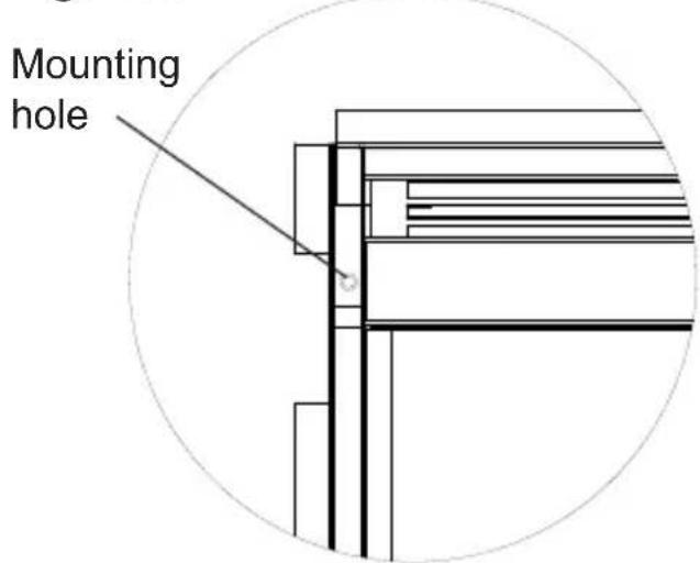
- Drive four (4) supplied mounting screws through the four (4) mounting holes located in each corner of the fireplace chassis, into wall studs (Figure 6).
- Refer to Front Glass Installation section, for final
Figure 4
natural_image
Isometric line drawing of a structural frame or panel assembly (no text or symbols)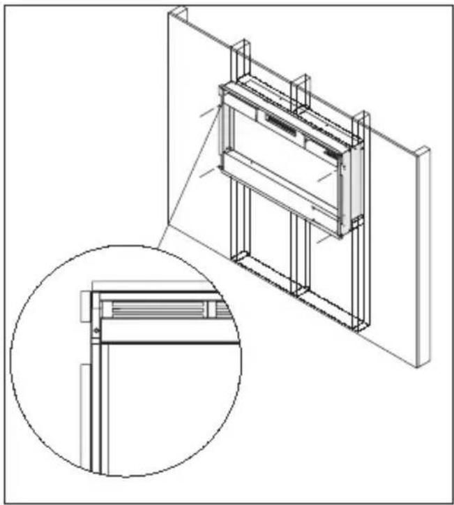
natural_image
Technical line drawing of a modular HVAC unit with structural supports and a magnified inset showing internal components (no text or symbols)
Fireplace Installation
Figure 6
installation procedures.
Flush Mounted Installation - 200mm Deep

CAUTION: Two people may be required for various steps of this procedure.
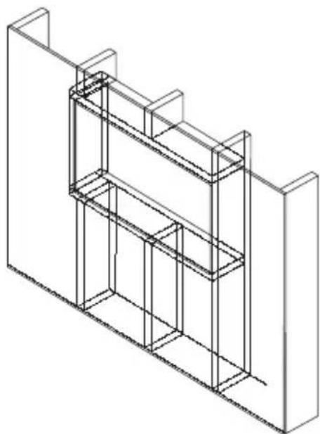
- Prepare a wall with a framed opening of 837mm wide x 470 mm high (Figure 7).
! NOTE: The sizing has allowed for approx 7mm around the fireplace insert for ease of installation. This fireplace does not require any additional venting.
- Choose your method of supplying power to the unit:
- Plug in (you may run the power cord out of the framed wall opening to an existing outlet or install an outlet on a nearby wall stud within the wall).
- Hard wire the fireplace.
! NOTE: Hard wiring can be done by removing the plug from the factory fitted cord and completing the wiring according to National and Local Electrical Codes. The appliance must be fitted with means for disconnection from the supply mains having a contact separation in all poles that provide full disconnection under overvoltage category III conditions, and these means must be incorporated in the fixed wiring in accordance with the wiring rules.
Figure 7
natural_image
Isometric line drawing of a multi-level building structure with vertical supports (no text or symbols)
Fireplace Installation
WARNING: Do not attempt to wire your own new outlets or circuits. To reduce the risk of fire, electric shock or injury to persons, always use a licensed electrician.
Ensure that the 3-Position Switch is set to the Off position ("O") and that the circuit on which the fireplace is to be installed has the power cut off at the service panel until installation is complete.
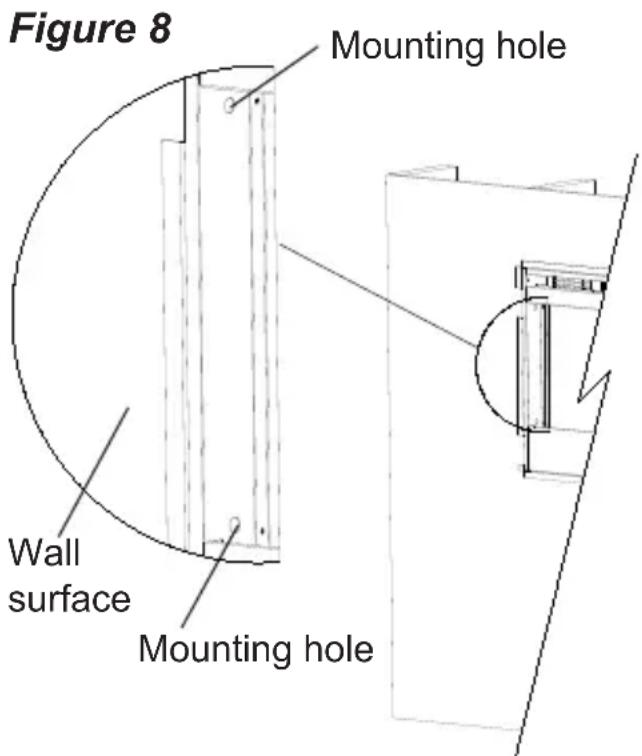
- Lift fireplace and insert into opening. The fireplace's mounting trim should be flush against the wall (Figure 8).
- Use bubble level (supplied) to level the fireplace within the framing. Adjust as required.
- Drive four (4) supplied mounting screws through the four (4) mounting holes located on the inside surface of the fireplace chassis, into wall studs (Figure 8).
- Refer to Front Glass Installation section, for final installation procedures.
Front Glass Installation
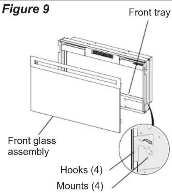
- Evenly distribute supplied glass rock on the front tray of the fireplace (Figure 9).
- Carefully mount front glass
assembly so that the front glass hooks (4) hang on the front glass mounts on the fireplace (4) (Figure 9).
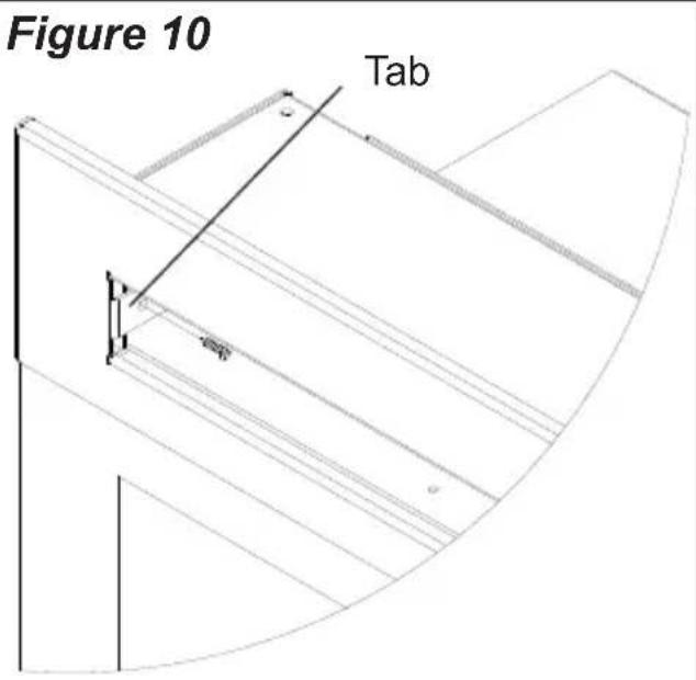
- Use the supplied two (2) Phillips sheet metal screws to fasten the glass assembly tabs to the fireplace (Figure 11).
- Ensure the fireplace's 3-Position Switch is switched to the Off position ("O").
- If unit is not hard-wired, plug fireplace into a 10 Amp, 230-240 Volt outlet.(refer to NOTE 1).

Operation
Figure 11
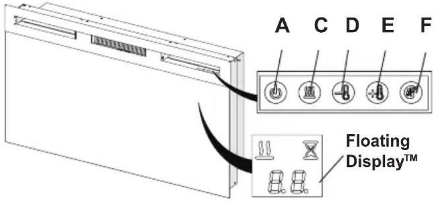
Figure 12
A B D F
WARNING: This electric firebox must be properly installed before it is used.
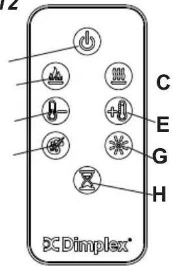
The unit can be controlled by either the manual controls which are located on the upper right of the fireplace or the remote (Figure 11 & 12).
The fireplace is supplied with an IR multifunction remote control.
! NOTE: To operate correctly, the remote control must be pointed towards the Floating Display™.
A. ⏻ Standby
Turns the unit On and Off.
→ Activated by pressing the Standby button on the remote or the unit.
• The unit will turn on with the same
functions that it was set to when it was turned Off and the intake temperature will be indicated on the Floating Display ^TM .
! NOTE: When any button is pressed the intake temperature will be displayed on the Floating Display™ for 5 seconds.
B. Flame Effects
Turns the flame effect On and Off.
→ Activated by pressing the button on the remote.
C. Heat ON/OFF
Turns the heater On and Off.
→ Activated by pressing the 🎨 button on the unit or the remote.

Operation
- Indicated by the 🎨icon and the intake temperature being displayed on the Floating Display™, for 5 seconds before turning off.
! NOTE: After the heater is switched off, there is a 60 second fan delay, where the fan will continue running before turning off.
! NOTE: The unit can be operated in Heat Only Mode. When the unit is only running with the heater, the 🎩icon will continuously be displayed on the Floating Display™.
! NOTE: The heater may emit a slight, harmless odor when first used. This odor is a normal condition caused by initial heating of internal heater parts and will not occur again.
D & E. Thermostat Controls
Adjusts the temperature set point to your individual requirements. Once the desired set temperature is reached the heater will turn off. The heater will cycle on and off to maintain the desired set temperature. The default temperature setting is 72^ F ( 22^ C).
→ Adjusted by pressing the to decrease the setpoint and the
+ to increase the setpoint on the unit or the remote.
- The Floating Display™ will indicate the temperature setpoint as it is adjusted.
! NOTE: Holding the + and the 🔒 buttons down for two seconds, on the unit, will change the temperature from °C to °F, or vice versa.
Disable Heat
If desired, depending on the season, the heater on the unit can be disabled. The unit will operate in the same fashion, with remainder of the controls.
Pressing the 🎨 and 🔒 — buttons on the unit at the same time and holding for 2 seconds will disable and enable the heater.
! NOTE: When the heater has been disabled and either the 🖱 or the + pressed the Floating Display™ will indicate "--".
F. Color Themes
Different presets of ambient lighting color combinations contained in the unit.

Operation
→ Changed by repeatedly pressing the corresponding button on the remote or the unit.
- Cycles through the different preset ambient lighting settings of the unit, this includes different combinations of colours of the flame base and media lighting.
! NOTE: The last theme of the cycle is a prism where the unit cycles through a variety of colours.
Pressing the ⚙ button stops the cycling and holds the unit on the preferred color, indicated by a "U" - Unfreeze or a "F" - Freeze on the display.
G. Brightness
Changes the brightness of the lights in the unit.
→Adjusted by repeatedly pressing the corresponding button on the remote.
- Indicated by the second digit on the Floating Display™ changing to show: "H" (high), and "L" (low).
H. Sleep Timer
The Sleep Timer can be set to automatically shut off the fireplace after a preset time (from 30 minutes to 8 hours).
→ To set the timer press the timer button on the remote, repeatedly, until the desired time is displayed.
- The Floating Display™ will display the different times as it is adjusted. Once the timer has begun, pressing the X button will display the time remaining before the unit turns Off.
! NOTE: The Sleep Timer can be cancelled at any time by pressing the 📄 button repeatedly until the sleep timer displays nothing.
Resetting the Temperature Cutoff Switch
Should the heater overheat, an automatic cut out will turn the whole unit off and it will not come back on without being reset. It can be reset by turning the unit off at the main disconnect panel and waiting 5 minutes before turning the unit back on.

Operation

Maintenance
Remote Control Battery Replacement
To replace the battery:
- Slide battery cover open on the remote control.
- Correctly install one 3 Volt (CR2032 [longer life] or CR2025) battery in the battery holder.
- Close the battery cover.

Battery must be recycled or disposed of properly. Check with your Local
Authority or Retailer for recycling advice in your area

WARNING: Disconnect wer before attempting any intenance or cleaning to uce the risk of fire, electric ock or damage to persons.
Partially Reflective Glass Cleaning
The partially reflective glass is cleaned in the factory during the assembly operation. During shipment, installation, handling, etc., the partially reflective glass may collect dust particles; these can be removed by dusting lightly with a clean dry cloth.
To remove fingerprints or other marks, the partially reflective glass can be cleaned with a damp cloth. The partially reflective glass should be completely dried with a lint free cloth to prevent water spots. To prevent scratching, do not use abrasive cleaners.

Maintenance
Fireplace Surface Cleaning
Use only a damp cloth to clean painted surfaces of the fireplace. Do not use abrasive cleaners.
Servicing
Except for installation and cleaning described in this manual, an authorized service representative should perform any other servicing.

Contact Details
Glen Dimplex Australia Pty Ltd
8 Lakeview Drive, Scoresby,
VIC 3179
Australia
Phone: 1300 556 816
Email: sales@glendimplex.com.au
Web: www.dimplex.com.au
Glen Dimplex New Zealand Pty Ltd
38 Harris Road
East Tamaki, 2013 Auckland
New Zealand
Ph: 0800 666 2824
Email: sales@glendimplex.co.nz
Web: www.dimplex.co.nz
- Table of Contents
- Welcome & Congratulations
- Please carefully read and save these instructions.
- NO NEED TO RETURN TO THE STORE
- IMPORTANT SAFETY INSTRUCTIONS
- Read all instructions before using this appliance.
- Site Selection
- Fireplace Installation
- Surface Installation
- In-wall Recessed Installation - 100mm Deep
- Flush Mounted Installation - 200mm Deep
- Front Glass Installation
- Operation
- ⏻ Standby
- Flame Effects
- Heat ON/OFF
- D & E. Thermostat Controls
- Disable Heat
- Color Themes
- Brightness
- Sleep Timer
- Resetting the Temperature Cutoff Switch
- Maintenance
- Remote Control Battery Replacement
- Partially Reflective Glass Cleaning
- Fireplace Surface Cleaning
- Servicing
- Contact Details
Brand : DIMPLEX
Model : Prism BLF3451-AU
Category : Fireplace