
GDS3710 - Video Intercom GRANDSTREAM - Free user manual and instructions
Find the device manual for free GDS3710 GRANDSTREAM in PDF.

| Product Type | IP Video Intercom |
| Brand | Grandstream |
| Model | GDS3710 |
| Dimensions (approx.) | 250 x 150 x 50 mm |
| Weight (approx.) | 1 kg |
| Power Supply | PoE Class 3 (48-57V) or DC 12V, 1A minimum |
| Power Consumption | Max 12W (PoE Class 3) |
| Operating Temperature | -30°C to 60°C |
| Operating Humidity | 10% to 90% RH (non-condensing) |
| Video Resolution | HD (1920x1080) |
| Viewing Angle | 120° (horizontal) |
| Audio | Built-in microphone and speaker, two-way audio |
| Network Interface | RJ45 10/100/1000 Mbps |
| Supported Protocols | SIP, HTTPS, IPv4/IPv6, DHCP |
| Main Functions | Video call, access control (electric lock), live viewing via web |
| Mounting | Wall (surface) or flush mount (optional kit) |
| Protection Rating | IP66 (weather resistant) |
| Security | Anti-tamper screws, web access via HTTPS, administrator password |
| Maintenance and Cleaning | Clean with a soft, dry cloth. Do not use abrasive products. |
| Spare Parts and Repairability | Contact Grandstream after-sales service or an authorized reseller. |
| General Information | Manual available in several languages at notice-facile.com. Weight and dimensions are approximate. |
Frequently Asked Questions - GDS3710 GRANDSTREAM
User questions about GDS3710 GRANDSTREAM
0 question about this device. Answer the ones you know or ask your own.
Ask a new question about this device
Download the instructions for your Video Intercom in PDF format for free! Find your manual GDS3710 - GRANDSTREAM and take your electronic device back in hand. On this page are published all the documents necessary for the use of your device. GDS3710 by GRANDSTREAM.
USER MANUAL GDS3710 GRANDSTREAM
Grandstream Networks, Inc.
126 Brookline Ave, 3rd Floor
Boston, MA 02215. USA
Tel: +1 (617) 566-9300
For Warranty and RMA information, please visit www.grandsstream.com
EU Agent:
Picus Advisors Ltd
Taivalmaki 9F1-02200 Espoo, FINLAND
https://www.picus.fi
Note: For European Union only
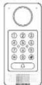
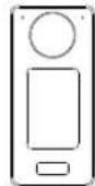
GDS3710
Hemispheric HD IP Video Door System
Quick Installation Guide
Content
English. 1
简体中文 11
Espanol. 21
Francais. 31
Deutsch. 41
Italiano. 51
Pycckn. 61
Portugues. 71
Polski. 81
PRECAUTIONS
- Do not attempt to disassemble or modify the device
- Strictly follow the requirement of power source
- Do not expose this device to temperatures out the range of -30^ to 60^ for operating and -35^ to 60^ for storage
- Do not expose this device to environments outside of the following humidity range: 10 - 90% RH (non-condensing)
- Please strictly follow the instruction to install or hire professionals to install properly
PACKAGE CONTENTS

MOUNTING GDS3710
On-Wall (Surface) Mounting
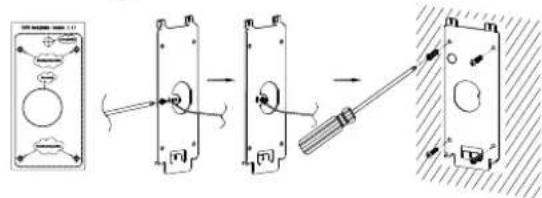
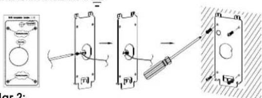
Step 1:
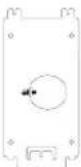
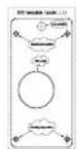
Refer to the "drilling template" to drill holes at targeted place on wall then mount the installation bracket using the four screws and anchors provided (screwdriver not provided). Connect and tight-en "Ground" wire to the bracket ground marked with printed icon
Step 2:
Pull Cat5e or Cat6 cable (not provided) through the rubber gasket selecting the correct size and the back cover panel piece, please refer to "GDS3710WIRINGTABLE" at the end of QIG for Pin connections.
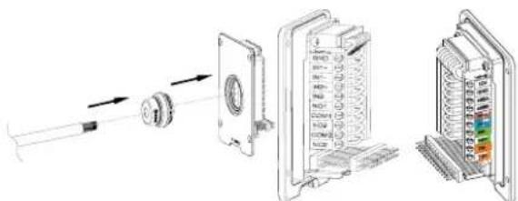
Note:
Needle nose plier highly recommended and 2.5mm flat screwdriver required (not provided). Stripping outer plastic shield of the cable in less than 2 inches suggested. Do NOT leave bare metal outside the socket by over stripping the inner plastic shield of the wires.
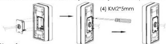
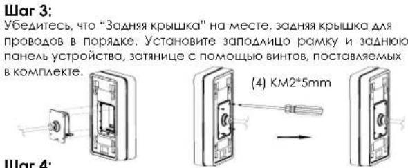
Step 3: Make sure the "Back Cover Frame" is in place, the wired back cover panel is good. Flush the back cover panel piece with the whole back surface of device, tighten it using the screws provided.
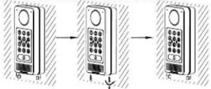
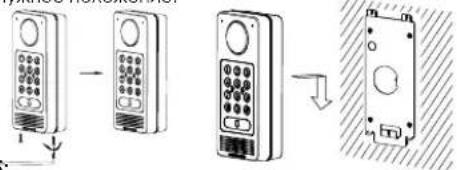
Step 4: Take out the two preinstalled anti-tamper screws using the hex key provided. Carefully align the GDS3710 to the metal bracket on wall, press and pull the GDS3710 down to the right position.
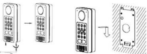
Step 5: Install the two anti-tamper screws back using the hex key provided (do NOT over tighten the screws). Cover the two screw holes on the bottom of "Back Cover Frame" piece using the two silicon plugs provided. Final check and finish the installation.
In-Wall (Embedded) Mounting
Please refer to the "In-Wall (Embedded) Mouting Kit", which can be purchased separately from Grandstream.
CONNECTING THE GDS3710
Refer to the illustration below and follow the instructions on the next page.
POWER OFF GDS3710 when connecting wires or inserting/removing the back cover panel piece!
Option A: RJ45 Ethernet Cable to (Class 3) Power over Ethernet (PoE) Switch.

Note: Choose Option A if using PoE switch (Class 3); OR: Option B if using 3rd party power source.
Option A
Plug an RJ45 Ethernet cable into the (Class 3) Power over Ethernet(PoE) switch.
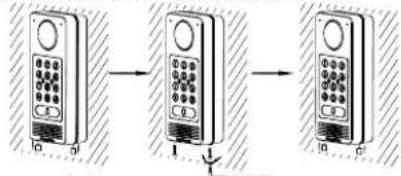
Option B
Step 1:
Select an external DC12V, minimum 1A power source (not provided). Wire correctly the "+" cable of the power into the "12V, GND" connector of the GDS3710 socket (refer to the previous mounting page for instruction). Connect the power source.
Step 2:
Plug an RJ45 Ethernet cable into a network switch/hub or router.
Note:
Please refer to "Step 2" of "MOUNTING GDS3710" and "GDS3710 WIRING TABLE" at the end of QIG for all the wiring and connection illustration and instructions.
GDS3710 CONFIGURATION
The GDS3710 is by default configured to obtain the IP address from DHCP server where the unit is located.
In order to know which IP address is assigned to your GDS3710, please use GS_Search tool as illustrated in following steps.
Note:
If no DHCP server is available, the GDS3710 default IP address (after 5 minutes DHCP timeout) is 192.168.1.168.
Step 1: Download and install GS_Search tool: http://www.grandstream.com/support/tools
Step 2: Run the Grandstream GS Search tool on a computer connected to same network/ DHCP server.
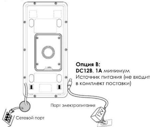
Step 3: Click on button to start device detection.
Step 4: The detected devices will appear in the output field as below.
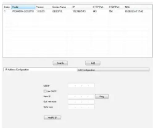
Step 5: Open the web browser and type the displayed IP address of GDS3710 with leading https:// to access the web GUI. (For security reasons, the default web access of GDS3710 is using HTTPS and port 443.)
Step 6: Enter username and password to login. (The default administrator username is "admin" and the default random password can be found at the sticker on the GDS3710).
Note: For security reasons, make sure to change the default admin password from System Settings > User Management.

Step 7: After login into the webGUI, click the left side menu in the web interface for more detailed and advanced configuration.
7 8
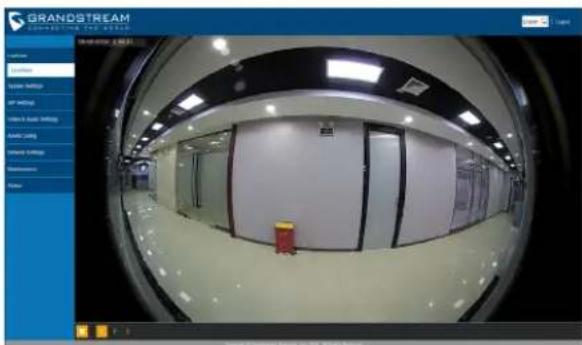
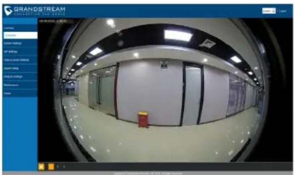
Step 8: To view video feed, access to LiveView .The browser will indicate that Active-X or Video Plug-in is required. Follow the displayed instruction to download and install it.
Click "Play" button to view the selected video feed.
Below is an example screenshot with the successful Active-X or Plug-in installation.
Refer to online documents and FAQ for more
detailed information:
http://www.grandsstream.com/our-products
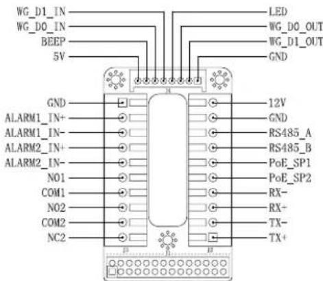
GDS3710 WIRING TABLE
| Jack Pin | Signd | Function |
| J2(Basic)3.81mm | 1 TX+(Orange/White) | Ethernet, PoE 802.3af Class3, 12.95W |
| 2 TX-(Orange) | ||
| 3 RX+(Green/White) | ||
| 4 RX-(Green) | ||
| 5 PoE SP2 (Blue + Blue/White) | ||
| 6 PoE SP1 (Brown + Brown/White) | ||
| 7 RS485 B | RS485 | |
| 8 RS485_A | ||
| 9 GND | Power Supply | |
| 10 2V | ||
| J3(Avanced)3.81mm | 1 GND | Alarm CND |
| 2 ALARM1_IN+ | ALARM IN | |
| 3 ALARM1_IN- | ||
| 4 ALARM2_IN+ | ||
| 5 ALARM2_IN- | ||
| 6 NO1 | Alarm Out | |
| 7 COM1 | ||
| 8 NO2 | Electric Lock | |
| 9 COM2 | ||
| 10 NC2 | ||
| J4(Special)2.0mm | 1 GND (Black) | Wiegand Power CND |
| 2 WG_D1_OUT (Orange) | Wiegand Output Signal | |
| 3 WG_D0_OUT (Brown) | ||
| 4 LED (Blue) | Wiegand Output LED Signal | |
| 5 WG_D1_IN (White) | Wiegand Input Signal | |
| 6 WG_D0_IN (Green) | ||
| 7 BEEP (Yellow) | Wiegand Output BEEP Signal | |
| 8 5V (Red) Wiegand Power Output | ||
For more details regarding GDS3710 wiring, please refer to User Manual.
| Electric Lock GDS3710 Connection | Door | ||||
| Type Power On Power Off NC2 | NO2 COM2 | Normal Status | |||
| Fail Safe Lock Open | ■ Lock | ||||
| ■ Open | |||||
| Fail Secure Open Lock | ■ Lock | ||||
| ■ Open | |||||
| NOTE: Please select the correct wiring based on different electric strike/lock and the normal status of door. Electric Magnetic Lock will work at Fall Safe mode ONLY. | |||||
Note:
1) Power PoE_SP1, PoE_SP2 with DC, the voltage range is 48V~57V, no polarity.
2) Power with PoE the cable wiring:
PoE SP1, brown and brown/white binding
- PoE SP2, blue and blue/white binding
3) DC Power could be correctly sourced from qualified PoE Injector.
This product is covered by one or more of the U.S. patents (and any foreign patent counterparts thereof) identified on www.rmpatents.com.
注意事项
http://www.grandstream.com/our-products
http://www.grondstream.com/our-products
TABLE DE CONNEXION DU GDS3710
| ConnecteurPI | NSignaFlonction | |
| J2(Basique)3.81mm | 1 TX+ (Orange/Blanc) | Ethemet, PoE 802.3af Class3, 12.95W |
| 2 TX- (Orange) | ||
| 3 RX+ (Veri/Blanc) | ||
| 4 RX- (Veri) | ||
| 5 PoE_5P2 (Bluc + Bluc/Blanc) | ||
| 6 PoE SP1 (Marron + Mar-ron/Blanc) | ||
| 7 RS485 B | RS485 | |
| 8 RS485_A | ||
| 9 CND | Source d'alimentation | |
| 10 L2V | ||
| J3(Avantée)3.81mm | 1 CND Masse Alarme | |
| 2 ALARM1_IN+ | Entrée Alarme | |
| 3 ALARM1_IN- | ||
| 4 ALARM2_IN+ | ||
| 5 ALARM2_IN- | ||
| 6 NO1 | Sortie Alarme | |
| 7 COM1 | ||
| 8 NO2 | Verrouillage Electrique9 Co | |
| 10 NC2 | ||
| J4(Speciale)2.0mm | 1 CND (Noir) Masse Wiegand | |
| 2 WG_D1_OUT(Orange) | Signal de sortie Wiegand | |
| 3 WG_D0_OUT(Marron) | ||
| 4 LED(Blau) | Signal de sortie LED Wie-gand | |
| 5 WG_D1_IN(Blanc) | Signal d'entree Wiegand | |
| 6 WG_D0_IN(Veri) | ||
| 7 BEEP(Jaune) | Signal de sortie Beep Wiegand | |
| 8 SV(Rouge)Alimentation Wiegand |
http://www.grandsstream.com/our-products
MEPbI IPEAOCTOPOXHOCTN
He nItaIteb otKpbibatb, pa36npaH NAn NImeHrtb yctpOCTBO
- Ctporo co6AIOaIte Tpe6oBaHn HCTOHTHKa NHTAHN
-He noaBepraTe BO3AeCTBnHO TEMnepaTpyb HBe dHaana3oHa ot-30°C 60°C npn 3Knayataun n ot -35°C 60°C npn xpaHHeHH
HeOnyckaeTcHCCNoA30BAtyCTPOIcTBnPnTHOCHTeALHO BAOXHOCTN BHE ANa3OHa 10-90 (6e3 KOHAcHcTa)
- PnKAsyIcTa, cTporo CLeAynTe NInHCTpyKUINM NO yCTAHOBKe HAIIMNTe npOpeccnHOHaAD AAR PPABNAHOBYCTAHOBKN
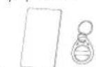
KOMIIAEKTIOCTABKN
1xKoHUITeH AAAyctaHOBOKI
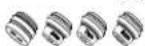


1xIIeCTHPOAHBKAOKIPOTHOB3AOMHOTCYPTOCTBA
1xKapTa paAnovactoTHO
AeHTHnKALMn
1xRFHD KAPN

6XBHNTHnDHKepbKPOHJUHTHO
IxKabeAb Wiegand

1x3aAHRAKpbLLKA

IXKTHBdAMOCHKTNANHbI

IXKpTKepyKOBCTBO
NoA3OBTeA
1XAIeHnGPL
MOHTAX GDS3710
HacteHHbI (noBepxHocTHbI) MOHTAX
War 1:
Ncnoa3yra"w6aoHAA CBepeHn" npocBepante OTBepTna Ha BbipahHom MeCTe Ha CTHe, 3ATEM CMOHTpyTE YCTAOBOHHBI KPOHLITEHN, Ncnoa3yra 4 BNHTA NHKEPA, BXOAJIuHE B KOMTAEKT NOCTABKN (OTBEPKBA KOMTAEKT He BXOAnI). POAKAOHTNE IN 3AKPENNTPEPOBAD 3a3EMeHnK 3eMaek PKOHLITEHNOMEYEHHOHKOH.
War 2:
PpOHTHHe Ka6eBcA15e HnCai6(He BxoAaBt B KOMNAEKTOCTBKN)peep3peHHOBYIO pOKAAqky, BbIbPaB HyKbHpa3Mepn,H 3aHOIO NaHEb, NOXAYnctA, CMOTpTeUbtpbKoBBHe COeAHENHnB T"BA5HNIE KABEAHON PA3BOADKnGDS 3710" B KOHue KpatKoro pykBOAcTBA no yCTaHOBe.

PnmeaHne:
PEKOMEHAYETCA HNOABOBATB OCTpOy6bln POCKYIO OTBepTKY 2.5 MM (HE BXOA8T B KOMPAEKT NOCTABKN).PEKOMEHAOBAHO 3aHIIATb PPOBOHa Ha MeHee He 2 AIOMa. HE AOYCKaTe HAHmOroA ORAHHO METAAH BHe PO3ETKn, B CaeACTBHe 13bIOTHO CHTRN NAGCTHKOBON H0AUNHN PPOBODa.
War 4: Bbkyntte ABA BNHTa 3aunntb ot BCKpBnra C nomouLbO UeTfPahHOTAO KAAQHa.TUATEAeBHO npKMMTE GDS3710 K Metaannneckon ckoBe Ha CTHe, HAKMITE N NotAHTE GDS3710 BHN3 BHYKHoe IOAOXEHNE.
War 5: BkyTInTe ABA BnHTa 3aunHbI O BCKpbHnBnHTbO6paTHo C nmoLIOu LueCTHPaHHO KAIOHa (He nepetraNBaTE BnHTb). 3aKpOte ABA OTBePCTNAA BnHTOB HnKHeY qactn "3aHei KpbUHK"HCNOAByA BBe pe3HOBbIX 3aayUk. CaeAitE cHNAHHy npOBepKY aBepUHtne yctAOHBKy.
HacteHHbB (BCTPOeHHbB) MOHTAX
Pokaaynta, HNOA3byte "KOMNAKT DAA HACTeHHoro
(BCTPOeHHoro) MOHTaKa, KOtOpB MoXHO OTaEaHo 3aKa3aTb B
KoMaNaHn Grandstream.
NOAKAOYEHGEDS3710 CMOTPNE HIO6paXeHHe HIXe N CLEdyTe INCTpyKUaM Ha cAeDyUoIe CTpaHnIe.
OTKAOHTe HNTAHNE GDS3710 npn noaKIOHcHHN PPOBOAOB NnnoaCOeAHHeHHN/OTCoeAHHeHHN 3aAHe NNOHEH
OnuA: RJ45 Ethernet Ka6eAb B (KAcc 3) Power over Ethernet (PoE) kommtyarop.
PnmeaHne:
Bb6epntoOnuA, npn nCnoAb3OBAHn PoE KOMMyTaTopa (Kacc 3);
NAI:OnuB, npn nCnoAb3OBAHn CTOpOHHeToCTOHHKa
PiHTAAH.
OnuA
BCTaBte RJ45 Ethernet ka6eAb B (Kaacc 3) Power over Ethernet(PoE) kOmmyiatop.
OnuB
War 1:
Bb6epnte BHEHIN HCTOHHN NHTAHN DC12B, MHHMmY 1A (He BXOANT B KOMTAEKT NOCTABKJI).PABNAHBO NOAKAOHYTE, COBAOADNOAOCOBKY ^+ , CAAOBIO Ka6eAb K pa3bEmy "12V, GND" rhe3daGDS3710 (HnCTpykUIN CMOTpHe Ha npeBaIyuee CTpaHnue).PiKaONHNE HCTOHHN THTAHN.
War 2:
PiKaIOHte Ethernet Ka6eAb K cTei, KOmmYatOpy/ KOHcHTpatOpTy Hm MapuPtyn3atOpy
PnmeaHne:
IpaKaAyncta,cmOpnte "Uar 2"Bpa3aeMe"MOHTAK GDS3710" nTAPAAUY KAEAbHOI PA3BOkIN GDS3710" B KOHeue KpaTKoHnCTpyKUnnNo yCtAHOBkeAAN3obpaxKeHn NnHcTpyKUnn PO p3BOKeN COeAnHEHNrA.
KOHΦIγPauJg GDS3710
No ymoan GDS3710 Hactpoen Ha noanyene IP-apeca ot DHCP-cebpapa KOTOPOM paonaoxeno yctpoictbo.
Ara TOrO 0To 6bl y3Hb KaKoIP-aDpe nPCHBOEH Baaemy GDS3710, NoaKaYrTa cNoAby3yIe CpeACTBo GS_SearCh, KAK oNkA3HO B HIXKcEAyUOuHXuAC
PnmuMeaHne:
ECAHDHCP Heaoctyhen, IP-apec GDS3710 no ymoaahnIO (hepe3 5 MInHT c TaMayTa DHCP) 6yder 192.168.1.168.
War 1: 3arpyynte uyctanohnne GS_Search tool: http://www.grandsstream.com/support/looks
War 2:3anyctnte GS_Search komnHn Grandstream Ho komblotepe, noaKIOUeyHOM K TOI ke cet/HDCHP-cebpety.
War3:UeAKHHTe HA KHOIky Search 3aIyCKa o6HApYxehnryCTpoiCTB.
War4:O6HApyXeHHoeYCTPOINCTBOOTOPa3HTCBAIOAEBBIOaKaK NOKa3aHO HIXke.
War 5: OTKpoIte Be6-6pay3ep N BBeIte OTo6paXeHHbI IPaDpe GDS3710 HauHnA C https:// AaB XoDa B Be6 TIN. (No coo6paKeHNAM 6eOanACHO, Aa Be6 aocTyNa GDS3710 nCnoAByet HTPS nOpT 443).
War 6: AAR BXOAG BBEANTE HMR NOAB3OBATEA IN NAPOA. (NMA NOAB3OBATEA DAMNHCTPATOPA NO YM0AQUHNO - "Admin", CAUYHbIIN NAPoA No YM0AQUHIO MOXHO HAHTH HA HAKAeKe Ha GDS3710).
PnMMeaHHe:No coo6paKHeHMAe3OanacHocTH,
OB8aTeAboH NmEHNTE npAOa aAMMHCTpATOPa NO
yMOAnHIO,pepeB A ChTeMaHbIe HAcTpoKn > YnpBaAeHne
NOAB3OBATEARMN.

War7: Pocae BxOaB Be6 HIN, UeAKHnTe No MeHO CxAeBa Be6 INHepeHcA AooE AeTaAAbbHbN pacuHpeHHbH hactpoek.
War 8: AANPOMOTPA BNAEOTPAHCARUN BOHNTBE LiveView. Bpaesep cooBHTO Heo6XoAMoCTN AcIve-X HAN BnDEO nAaHHa.CaeyITE OTo6pKaqMaBM INHCTpyKUHM AIN X CCKAHBAHNN YCTHOKN.
山AKHNTe no KHOKNE "Bocnpn3BecTH" AAR npocMOTpa Bb6paHHBnEOTpHaCnIN.
Hnke nokazoh ckpHHoT C npmepom ycneuho yctahOBKn Active-XnnnnaHa.
CMOTPHTe 3AekTPOHHBIE AOKyMeHbI n pa3aEA FAQ AAR 6oae noapobho HnΦopmauH:
http://www.grandstream.com/our-products
TABLEA DE Cabeamento DO GDS3710
| Jack-paëbëm | Ums | Cunhãn ΦúkHz | |
| J2 (Bazobë) 3.81mm | 1 TX+ (Орathкавл/Белý) | PoE 802.3cf Káacc3.12.95W | |
| 2 TX- (Орathнковы) | |||
| 3 RX+ (Зелýнь/Белý) | |||
| 4 RX- (Зелýнь) | |||
| 5 PoE SP2 (Синý +Синý/Белý) | |||
| 6 PoE SP1 (Коринець +Коринець/Белý) | |||
| 7 RS485 B | RS485 | ||
| 8 RS485_A | |||
| 9 CND | Балok ПИТАПИA | ||
| 10 D2V | |||
| J3 (RocL-PoHBM) 3.81mm | 1 GND | Синданетор задеменя | |
| 2 ALARM1 IN+ | Alarm BxOΔ | ||
| 3 ALARM1_IN- | |||
| 4 ALARM2_IN+ | |||
| 5 ALARM2_IN- | |||
| 6 NO1 | Alarm BxOΔ | ||
| 7 COM1 | |||
| 8 NO2 | Зелектуеский замок | ||
| 9 COM2 | |||
| 10 NC2 | |||
| J4 (CinL-PoHBM) 2.0mm | 1 GND (Черный) Wiegand GND | Wiegand blyxoановСИНДA | |
| 2 WG_D1_OUT (Орathкавл) | |||
| 3 WG_D0_OUT (Коринець) | |||
| 4 LED (Синý) | Wiegand blyxoановСИНДСИA | ||
| 5 WG_D1 IN (Белý) | Wiegand aхоановСИНДA | ||
| 6 WG_D0_IN (Зелýнь) | |||
| 7 BEEP (Жытý) | Wiegand abyxoанов3БукововСИНДA | ||
| 8 SV (Красный) | Wiegand blyxoановMOLUHOCb | ||
Aa 60ae noopobohn HcfoMaunn O KaebHoH pa3BOKe GDS3710, noxanyiCTa, CMOTpnte PykoB0ACTBO NOABOBATEA.

6 x Bucas e parafusoso Supporting of installation

4 x Parafuso de seguranga
Chave sexttavada [len] de seguranga
1x Cabo Wiegand
1 x Pano de limpeza da lenle
1 x Cartao RFID 1 x Chaveiro RFID

http://www.grandstream.com/our-products
TABLEA DE Cabeamento DO GDS3710
| TomadaPIN Sinali:função | ||
| J2(Básico)3.81mm | 1 TX+ (Laranja/ Branco) | Ethemet, PoE 802.3af Class3, 12.95W |
| 2 TX- (Laranja) | ||
| 3 RX+ (Verde/ Branco) | ||
| 4 RX- (Verde) | ||
| 5 PoE_5P2 (Azul + Azul/ Branco) | ||
| 6 PoE SP1 (Castanho + Castanho/ Branco) | ||
| 7 RS485 B | RS485 | |
| 8 RS485_A | ||
| 9 GND | Fonde de alimentação | |
| 10 V2V | ||
| J3(Avantagem)3.81mm | 1 GND Alerramento do Alarme | |
| 2 ALARM1_IN+ | ALARM IN | |
| 3 ALARM1_IN- | ||
| 4 ALARM2_IN+ | ||
| 5 ALARM2_IN- | ||
| 6 NO1 | Alarm Out | |
| 7 COM1 | ||
| 8 NO2 | Fechadura Elétrica9 COM | |
| 10 NIC2 | ||
| J4(Espezial)2.0mm | 1 GND (Negro) Wiegand Power GND | |
| 2 WG_D1_OUT (Laranja) | Sinal de saía Wiegand | |
| 3 WG_D0_OUT (Castanho) | ||
| 4 LED (Azul) | Sinal de saía Wiegand LED | |
| 5 WG_D1_IN (Branco) | Sinal de entrada Wie-gand | |
| 6 WG_D0_IN (Verde) | ||
| 7 BEEP (Amarelo) | Beep do sinal de saía Wiegand | |
| 8 SV (Vermelho) | Saida de energia Wie-gand | |
http://www.grandsstream.com/our-products
TABLEA PRZEWODOW GDS3710