IAN 315093 - Faucet MIOMARE - Free user manual and instructions
Find the device manual for free IAN 315093 MIOMARE in PDF.
| Product type | Basin mixer tap |
| Brand | Miomare |
| Model | IAN 315093 |
| Intended use | Hot/cold water regulation for washbasins, pressure systems ≥ 1.5 bar |
| Connections | G 3/8" |
| Minimum flow pressure | 1.5 bar |
| Eco function | Flow limited to approx. 6 l/min, saves up to 50% water |
| Delivery contents | Tap with fixing kit, waste fitting, 2 flexible hoses, Allen key, manual |
| Main material | Chrome-plated brass |
| Minimum ambient temperature | 0 °C |
| Maintenance | Clean with soft cloth and mild detergent; descale aerator |
| Wear parts | Replaceable cartridge |
| Safety | Installation by a specialist recommended; turn off water before mounting |
| Warranty | 5 years from date of purchase |
| After-sales service | K&H Sanitary GmbH, Daimlerstraße 45, D-50170 Kerpen, Germany |
Frequently Asked Questions - IAN 315093 MIOMARE
User questions about IAN 315093 MIOMARE
0 question about this device. Answer the ones you know or ask your own.
Ask a new question about this device
Download the instructions for your Faucet in PDF format for free! Find your manual IAN 315093 - MIOMARE and take your electronic device back in hand. On this page are published all the documents necessary for the use of your device. IAN 315093 by MIOMARE.
USER MANUAL IAN 315093 MIOMARE
text_image
PDF ONLINE www.lidl-service.com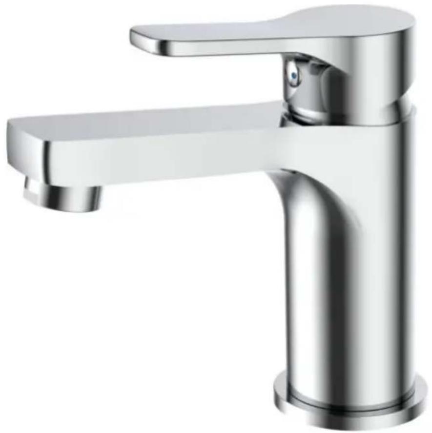
natural_image
Modern stainless steel faucet with handle and faucet (no text or symbols visible)BASIN MIXER TAP
GB IE NI
BASIN MIXER TAP
Assembly, operating and safety instructions
FR BE
MITIGEUR DE LAVABO
Before reading, unfold the page containing the illustrations and familiarise yourself with all functions of the device.
DK
GB/IE/NI Assembly, operating and safety instructions Page 5
text_image
Exploded view diagram of a kitchen sink assembly with numbered parts for identificationList of pictograms used....Page 6
Introduction......Page 6
Intended use....Page 6
Parts description Page 6
Technical data......Page 7
Delivery contents....Page 7
Safety instructions....Page 7
Installation......Page 7
Installing the tap....Page 8
Setting up the drain plug....Page 8
Installing the drain set....Page 8
Initial use....Page 9
Operation Page 9
Using the Eco function (water saving effect)....Page 9
Maintenance and cleaning......Page 9
Cleaning the tap Page 9
Replacing the cartridge Page 10
Disposal Page 10
Information......Page 10
Checking if tap water is drinkable....Page 10
Warranty and Service......Page 10
| List of pictograms used | |||
 | Read the assembly and operating instructions! | Danger to life and risk of accidents for infants and children | |
 | Observe the warnings and safety instructions! | Warning - risk of electric shock!Danger to life! | |
  | There is a danger of severe or fatal injuries! | ||
Basin Mixer Tap
- Introduction
Congratulations on the purchase of your new product. You have chosen a high-quality product. The assembly and operating instructions are part of this product. Please read these assembly and operating instructions carefully before use and observe all the information. These instructions contain important information about installation, settings and care. Therefore we ask that you retain these assembly and operating instructions and pass them on to any future owner.
Intendeduse
The tap is exclusively designed for the regulation of hot and cold water flow and for installation on washbasins. This tap is suitable for use with all pressure-tight hot water systems such as central heating, instantaneous water heaters, pressurised boilers, etc. It is not suitable for low pressure water heaters such as wood or coal water heaters, oil or gas water heaters or open electrical storage heaters. If in doubt, consult a plumber or heating specialist. Any use for purposes other than those specified above or any modification to the tap is not permitted and may cause damage to the tap. Furthermore, improper use may result in life-threatening risks and injuries. The tap is only for private use and is not intended for medical or commercial use. The manufacturer is not liable for damages due to improper use.
Partsdescription
| 1 | Tap lever* |
| 2 | Hot/cold plaque* |
| 3 | Allen grub screw* |
| 4 | Tap spout* |
| 5 | Aerator seal* |
| 6 | Aerator* |
| 7 | Aerator housing* |
| 8 | Tap body* |
| 9 | Base ring |
| 10 | Base ring seal |
| 11 | Drain plug* |
| 12 | Adjusting screw* |
| 13 | Lock nut* |
| 14 | Upper part of the drain set* |
| 15 | Upper drain seal* |
| 16 | Lower drain seal* |
| 17 | Lower part of the drain set* |
| 18 | Threaded flange |
| 19 | Wide sealing ring* |
| 20 | Allen key |
| 21 | Sphere* |
| 22 | Narrow sealing ring* |
| 23 | Eccentric nut* |
| 24 | Clamping plate* |
| 25 | Eccentric rod* |
| 26 | Eccentric connection* |
| 27 | 2 x Connecting hose (flexible) |
| 28 | Lower part of the pull rod |
| 29 | Upper part of the pull rod |
| 30 | Tap thread* |
| 31 | Sealing ring |
| 32 | Washer |
| 33 | Fastening nut |
| 34 | Cartridge base* |
35 Cartridge*
36 Cartridge safety device*
37 Cartridge covering ring*
*pre-assembled
- Technical data
Connections: G 38 " (G 12 " for Great Britain) Minimum flow pressure: 1.5 bar
- Delivery contents
1 Bathroom tap including fastening kit
1 Drain set
2 Flexible connecting hoses 38 (1/2" for Great Britain)
1 Allen key
1 Assembly and operating instructions

Safety instructions
KEEP ALL SAFETY INFORMATION AND INSTRUCTIONS FOR FUTURE REFERENCE.
DANGER TO LIFE AND RISK OF ACCIDENTS FOR INFANTS AND CHILDREN! Do not allow
children to play with the tap or to carry out cleaning or user maintenance unsupervised.
Do not allow children to play with the packaging film or parts of the packaging, otherwise they may become entangled in it whilst playing or swallow parts and suffocate.
BEWARE OF ELECTRIC SHOCK!
Any leaks or water discharge can cause danger to life through electric
shock.
- Check carefully that all connections are water-tight and that all wires for electrical devices near the sink unit are correctly and safely installed.
■ If in doubt, seek specialist advice.
■ CAUTION! DANGER OF SCALDING!
Ensure that the hot/cold plaque is inserted in
the correct position in order to avoid accidental scalding.
- Set the tap lever to open on a cold setting and then proceed to adjust the water temperature.
■ CAUTION! PROPERTY DAMAGE! Property damage can be caused by improper installation and use of the tap. Installation should be performed by a professional.
Before installation, turn off the water supply to your living area.
During installation, make sure that all the seals are placed correctly on the sealing surfaces. - Do not use the tap with low pressures and small-scale tank heaters.
■ Only use the tap if the ambient air temperature is above 0 °C.
If there is a danger of frost, cut off the water supply and drain the tap.
Do not use the tap if it displays signs of damage or its functionality is compromised.
■ Any leaks or water discharge can cause considerable damage to buildings and property. Therefore check carefully that all connections are watertight.
Before installation, familiarise yourself with all the on-site conditions, e.g. the available water connections and the shut-off device.
Do not carry out repairs yourself, instead hire a professional.
■ Only replace defective parts with original replacement parts.
- Installation
■ CAUTION! Turn off the hot and cold water supplies before you begin the installation.
■ CAUTION! Do not twist the connecting hoses and do not pull them taut.
■ CAUTION! Only screw on the connecting hoses by hand. Do not use pliers or a wrench, or else you could damage the connecting hoses.
Note: For the installation you will need a slot screwdriver and an open-end spanner SW 10 mm.
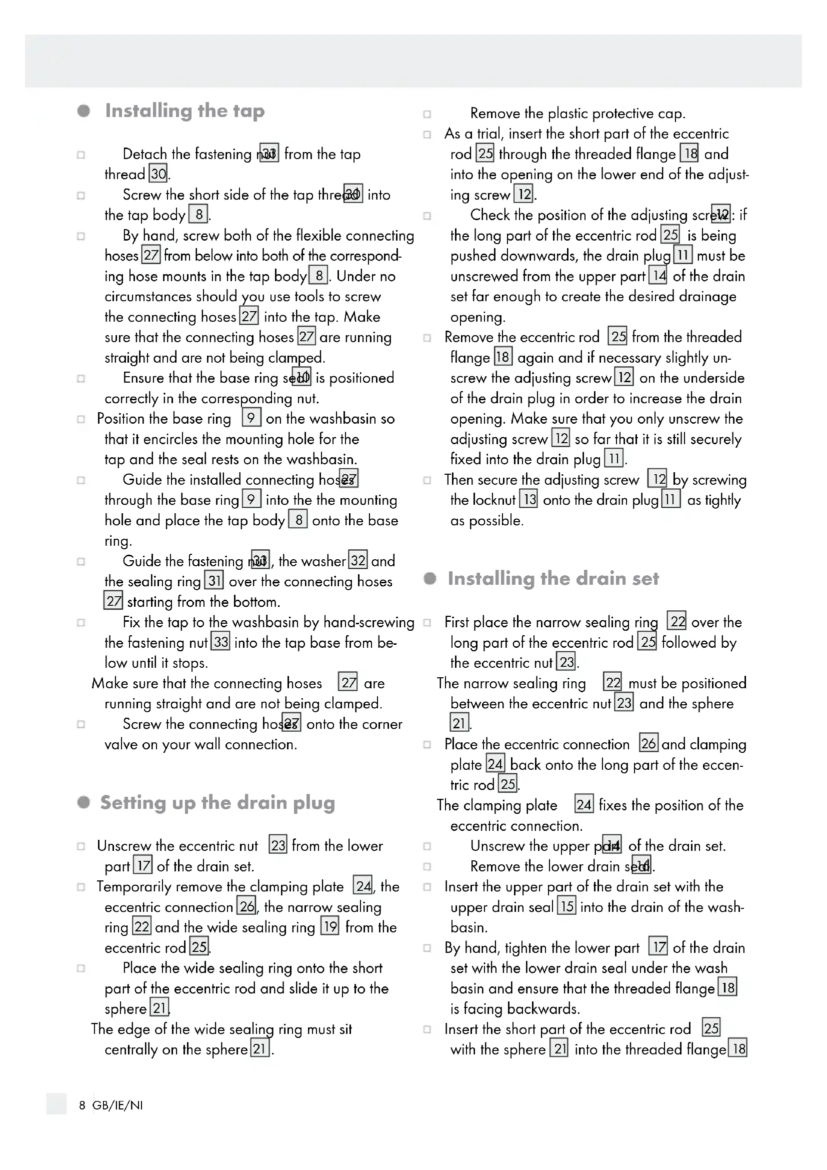
- Installing the tap
☐ Detach the fastening 33 from the tap thread 30.
Screw the short side of the tap three into the tap body 8.
By hand, screw both of the flexible connecting hoses 27 from below into both of the corresponding hose mounts in the tap body 8. Under no circumstances should you use tools to screw the connecting hoses 27 into the tap. Make sure that the connecting hoses 27 are running straight and are not being clamped.
☐ Ensure that the base ring set 10 is positioned correctly in the corresponding nut.
☐ Position the base ring 9 on the washbasin so that it encircles the mounting hole for the tap and the seal rests on the washbasin.
Guide the installed connecting hos23 through the base ring 9 into the the mounting hole and place the tap body 8 onto the base ring.
☐ Guide the fastening ring, the washer 32 and the sealing ring 31 over the connecting hoses 27 starting from the bottom.
Fix the tap to the washbasin by hand-screwing the fastening nut 33 into the tap base from below until it stops.
Make sure that the connecting hoses 27 are running straight and are not being clamped.
Screw the connecting hos28 onto the corner valve on your wall connection.
- Setting up the drain plug
☐ Unscrew the eccentric nut 23 from the lower part 17 of the drain set.
☐ Temporarily remove the clamping plate 24, the eccentric connection 26, the narrow sealing ring 22 and the wide sealing ring 19 from the eccentric rod 25.
Place the wide sealing ring onto the short part of the eccentric rod and slide it up to the sphere 21.
The edge of the wide sealing ring must sit centrally on the sphere 21.
Remove the plastic protective cap.
As a trial, insert the short part of the eccentric rod 25 through the threaded flange 18 and into the opening on the lower end of the adjusting screw 12.
Check the position of the adjusting screw: if the long part of the eccentric rod 25 is being pushed downwards, the drain plug 11 must be unscrewed from the upper part 14 of the drain set far enough to create the desired drainage opening.
Remove the eccentric rod 25 from the threaded flange 18 again and if necessary slightly unscrew the adjusting screw 12 on the underside of the drain plug in order to increase the drain opening. Make sure that you only unscrew the adjusting screw 12 so far that it is still securely fixed into the drain plug 11.
☐ Then secure the adjusting screw 12 by screwing the locknut 13 onto the drain plug 11 as tightly as possible.
- Installing the drain set
☐ First place the narrow sealing ring 22 over the long part of the eccentric rod 25 followed by the eccentric nut 23.
The narrow sealing ring 22 must be positioned between the eccentric nut 23 and the sphere 21.
Place the eccentric connection 26 and clamping plate 24 back onto the long part of the eccentric rod 25.
The clamping plate 24 fixes the position of the eccentric connection.
□ Unscrew the upper pda of the drain set.
Remove the lower drain set.
☐ Insert the upper part of the drain set with the upper drain seal 15 into the drain of the wash-basin.
By hand, tighten the lower part 17 of the drain set with the lower drain seal under the wash basin and ensure that the threaded flange 18 is facing backwards.
☐ Insert the short part of the eccentric rod 25 with the sphere 21 into the threaded flange 18
so that the eccentric rod 25 passes into the opening on the lower end of the adjusting screw 12.
☐ Screw the eccentric nut 23 with the narrow sealing ring onto the threaded flange 18.
☐ Insert the upper part 29 of the pull rod through the corresponding hole in the tap body 8.
☐ Insert the lower part 28 of the pull rod through the eccentric connection.
☐ Screw both parts of the pull rod together.
☐ Fix the lower part of the pull rod into the eccentric connection by tightening the cross-head screw.
☐ Check that the drain set is working properly.
☐ If necessary, adjust the position of the eccentric connection on the lower part of the pull rod by loosening the cross-head screw by a few turns and tightening it again after adjusting.
After successfully installing the product, turn on the hot and cold water supplies.
- Initial use
After the first use, carefully check all connections for leaks. In order to remove any possible impurities, the tap must be flushed before the first use.
To do this, proceed as follows:
□ Unscrew the aerator housing 19, the aerator 20 and the aerator seal 21 from the tap spout 4 in an anti-clockwise direction.
Open the main water supply and allow the water to flow for two minutes to flush out any residues.
☐ Then screw the aerator housing 19, the aerator 20 and the aerator seal 21 back onto the tap spout 4 in a clockwise direction.
Operation
☐ Tilt the tap lever 1 upwards or press it downwards to regulate the strength of the water flow.
Turn the tap lever 1 in either a clockwise or anti-clockwise direction to regulate the temperature of the water flow:
For cold water, turn the tap lever 1 anti-clockwise (to the right).
For hot water, turn the tap lever 1 clockwise (to the left).
● Using the Eco function (water saving effect)
The cartridge in this tap has an Eco function. When you move the tap lever 1, you will notice a slight resistance.
The Eco function limits the water flow to 6 l/min. This allows you to save up to 50% more water.
Tilt the tap lever until you notice a slight resistance.
☐ To increase the flow rate, exert slight pressure on the tap lever 1 until you overcome the resistance.
● Maintenance and cleaning
■ CAUTION! RISK OF DAMAGE! In order to properly clean and maintain the tap, observe the following instructions to avoid damage.
Never clean with petrol, solvents or abrasive cleaners, or hard bristled brushes etc. This could damage the tap surface.
- Cleaning the tap
Dry off your taps with a cloth after every use in order to prevent a build-up of limescale.
☐ Wipe the tap clean using a damp, soft cloth and if necessary, a mild cleaning agent.
To clean the aerator 6, unscrew the aerator housing 7 in an anti-clockwise direction and remove the aerator 6 from the aerator seal 5. Clean any limescale from the aerator and then screw the individual parts back together.
- Replacing the cartridge
Cartridges are wearing parts that must be replaced at regular intervals depending on the lime content and contamination levels of the water. If the tap lever becomes stiff to operate, this can be a sign that the cartridge must be replaced. Replacement cartridges can be obtained directly at the specified service point.
Proceed as follows:
☐ Carefully remove the hot/cold plaque 2 from the tap lever 1 with the help of a small flat-tip screwdriver.
☐ Loosen the underlying Allen grub screw 3 using the Allen key 20 by turning it anti-clockwise for a few turns. Do not unscrew the Allen grub screw 3 completely, only loosen it until the tap lever 1 can be easily removed.
Remove the tap level.
□ Unscrew the cartridge covering ring by hand in an anti-clockwise direction.
□ Unscrew the cartridge safety device 36 using a pipe wrench in an anti-clockwise direction.
☐ Pull the cartridge 35 out.
☐ Carefully insert the new cartridge.
Make sure that the seals under the cartridge are positioned correctly and that the leads are inserted into the openings provided.
Screw in the cartridge safety device tightly using a pipe wrench.
☐ Screw in the cartridge covering ring tightly by hand.
☐ Insert the tap lever into the cartridge.
Fix the tap level by tightening the Allen grub screw 3 in a clockwise direction using the Allen key 20.
☐ Insert the hot/cold plaque into the tap lever 1. Pay attention to the correct orientation: left = red (hot water) right = blue (cold water).
Note: If you tighten the cartridge safety ring too firmly, the tap lever 1 can be very difficult to move. In this case, slightly loosen the cartridge safety ring again.
●Disposal
The packaging is made entirely of recyclable materials, which you may dispose of at local recycling facilities.
Contact your local refuse disposal authority for more details of how to dispose of your worn-out product.
- Information
- Checking if tap water is drinkable
Ask your local authorities whether the water in your town/municipality is drinkable.
In general the following recommendations apply for the drinking water quality of tap water:
☐ Do not use any stagnant water to prepare dishes or drinks, and in particular to feed infants.
Failure to observe these instructions may have negative health effects. You can tell when water is fresh because it comes out of the tap noticeably colder than stagnant water.
☐ Run water from the tap for a short while if the tap has not been used for longer than four hours.
☐ If you are allergic to nickel, do not use any stagnant water from chromed pipes either for consumption or for washing in. Such water can have a high nickel content and can cause allergic reactions.
☐ Do not use drinking water from pipes containing lead to prepare food for infants and / or to prepare foods during pregnancy.
Lead is released into drinking water and poses particular heath dangers for pregnant women, infants and small children.
● Warranty and Service
The product has been manufactured to strict quality guidelines and meticulously examined before delivery. In the event of product defects you have legal rights against the retailer of this product. Your legal
rights are not limited in any way by our warranty detailed below.
The warranty for this product is 5 years from the date of purchase. Should this product show any fault in materials or manufacture within 5 years from the date of purchase, we will repair or replace it - at our choice - free of charge to you.
The warranty period begins on the date of purchase. Please keep the original sales receipt in a safe location. This document is required as your proof of purchase. This warranty becomes void if the product has been damaged, or used or maintained improperly.
The warranty applies to defects in material or manufacture. This warranty does not cover product parts subject to normal wear, thus possibly considered consumables (e.g. batteries) or for damage to fragile parts, e.g. switches, rechargeable batteries or glass parts.
Customer service
K&H Sanitary GmbH
DaimlerstraBe 45
D-50170 Kerpen
DEUTSCHLAND
Tel: 0049 2273 56680
Fax: 0049 2273 566825
E-Mail: service@kh-sanitary.de
IAN 315093\_1904
For all enquiries please have your receipt and the article number e.g. IAN 12345 ready as your proof of purchase.
De anvendte piktogrammers legende....Side 14
Indledning ......Side 14
Montering....Side 15
PRENEZ GARDE AU RISQUE

links = rot (Warmwasser)