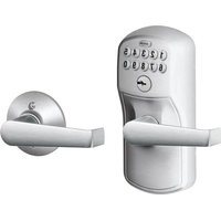
FE410 - Smart lock Schlage - Free user manual and instructions
Find the device manual for free FE410 Schlage in PDF.
| Product type | Smart lock with deadbolt and latch |
| Brand | Schlage |
| Model | FE410 (Control™) |
| Power supply | Batteries (not included, type not specified) |
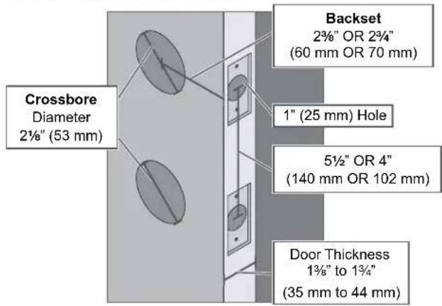
| Backset | 60 mm (2 3/8") or 70 mm (2 3/4") |
| Compatible door thickness | 35 to 44 mm (1 3/8" to 1 3/4") |
| Bore hole diameter | 53 mm (2 1/2") |
| Weight | Approximately 1.5 kg (estimated) |
| Material | Metal and robust plastic |
| Main functions | Locking/unlocking via code, key or smartphone; exterior lever free without code |
| Latch type | Deadbolt and latch |
| Security | Fire bolt included; break-in resistance |
| Installation | On existing door, tools: Phillips screwdriver, tape measure |
| Maintenance | Clean with a soft dry cloth; do not use chemicals |
| Compatibility | Works with Schlage Control™ systems and mobile apps |
| Number of batteries | Not specified, probably 4 AA batteries |
| Connectivity type | Wireless (Bluetooth or Z-Wave, depending on version) |
| Repairability | Spare parts available via customer service |
| Customer service | 1-800-847-1864 (Allegion) |
Frequently Asked Questions - FE410 Schlage
User questions about FE410 Schlage
0 question about this device. Answer the ones you know or ask your own.
Ask a new question about this device
Download the instructions for your Smart lock in PDF format for free! Find your manual FE410 - Schlage and take your electronic device back in hand. On this page are published all the documents necessary for the use of your device. FE410 by Schlage.
USER MANUAL FE410 Schlage
with Engage Technology

Installation Instructions
Credentials not included.
Warnings and Cautions

WARNING
Warnings indicate potentially hazardous conditions, which if not avoided or corrected, may cause death or serious injury.

CAUTION
Cautions indicate potentially hazardous conditions, which if not avoided or corrected, may cause minor or moderate injury. Cautions may also warn against unsafe practices.
Caution: Cautions indicate a condition that may cause equipment or property damage only.
Prepare for Installation
Tools Needed
• Phillips screwdriver
- Tape measure
Optional Tools
- Flathead screwdriver
- Torx ^TM driver
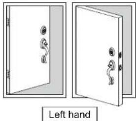
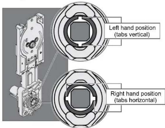
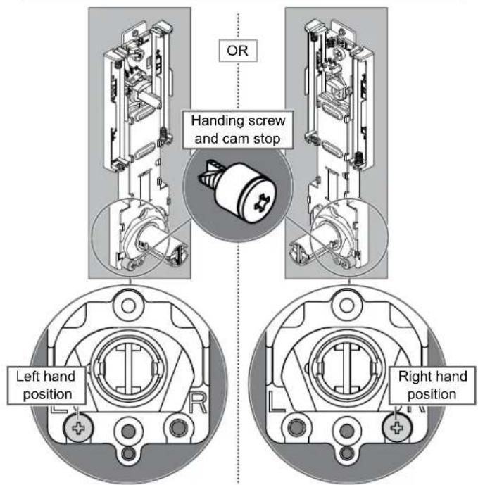
Determine the Handing
Determine the handing of your door. Directions for changing lock handing are provided throughout the instructions.
Outside of door
natural_image
Diagram showing two open doors with handles and a left-hand door, no text or symbols present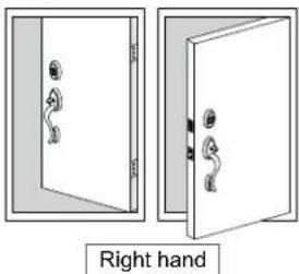
natural_image
Two views of a door with handles, one open and one closed, labeled 'Right hand' below (no other text or symbols)
CAUTION
If the handing is incorrect, locking and unlocking could be reversed, resulting in an unsecured residence.
Important Notes

WARNING
Install and test lock with door open to avoid being locked in or out!
Caution: Use provided bolt!
DO NOT use a power drill for installation!
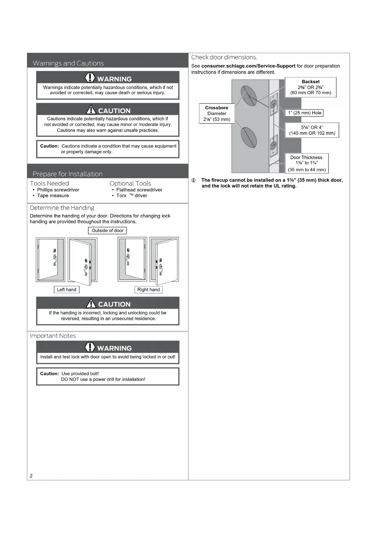
Check door dimensions.
See consumer.schlage.com/Service-Support for door preparation instructions if dimensions are different.
① The firecup cannot be installed on a 1 ^3/8 " (35 mm) thick door, and the lock will not retain the UL rating.
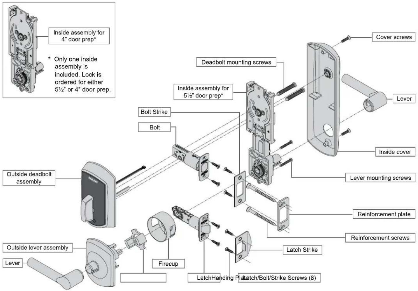
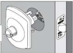
Install the Lock
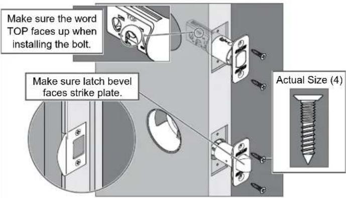
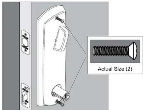
1 Install the bolt and latch.
Caution: Use provided bolt!
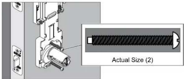
1a Adjust bolt length, if necessary.
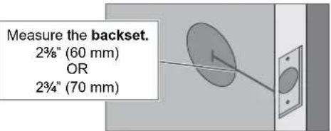
If the measurement is 234 " (70 mm), extend the bolt.
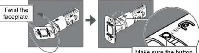
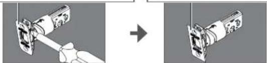
1b If desired, change to the square-corner faceplate.
- Use a flathead screwdriver to pry the faceplate off.
natural_image
Diagram showing a hand holding a device before and after transformation, with no visible text or symbols① The faceplate for the latch can be changed in the same way.
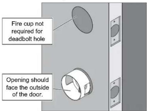
1c Install the firecup into the lower hole.
① DO NOT install the firecup on a 1 ^3/8 " thick door.
1d Install the bolt and the latch into the door.
CAUTION
If the bolt does not remain retracted throughout installation, locking and unlocking could be reversed, resulting in an unsecured residence.
2 Install the top part of the lock.
2a Install the outside deadbolt assembly on the outside of the door.
CAUTION
If the bolt does not remain retracted throughout installation, locking and unlocking could be reversed, resulting in an unsecured residence.
2b Adjust the spindle on the inside assembly, if necessary.

CAUTION
If the spindle is not in the correct position, locking and unlocking could be reversed, resulting in an unsecured residence.
① See Determine the Handing on page 2 to determine the hand of your door.
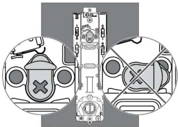
2c Make sure the cam on the inside assembly is in the correct position.

CAUTION
If the cam is not in the correct position during installation, locking and unlocking could be reversed, resulting in an unsecured residence.
natural_image
Diagram showing safety symbols and crossed-out device layout (no text or labels)2d Install the inside assembly on the inside of the door.
① Bolt must remain retracted!
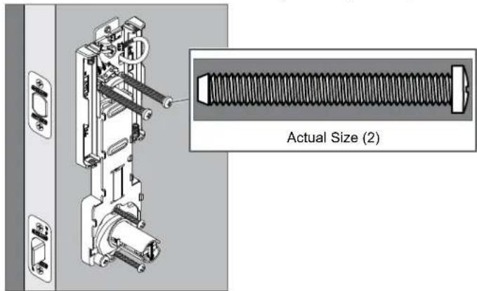
2e Secure the inside assembly with the two top screws.
① If the screw holes are blocked by the cam, see step 2c.
3 Install the bottom part of the lock.
3a Install the handing plate into the lever assembly.
CAUTION
If the handing plate is not in the correct position, locking and unlocking could be reversed, resulting in an unsecured residence.
① See Determine the Handing on page 2 to determine the hand of your door.
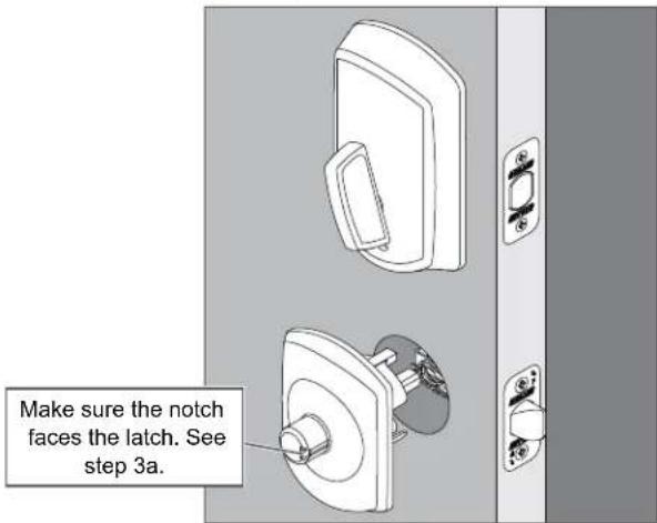
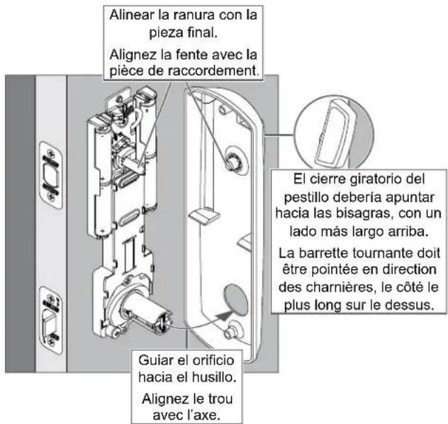
- Rotate the assembly so the notch faces the latch
natural_image
Technical illustration of a mechanical assembly with a flanged component and a separate close-up view (no text or symbols)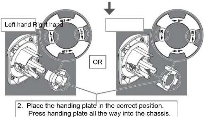
3b Install the lever assembly on the outside of the door.
① The lever will be installed later.
3c Secure the inside assembly with the two bottom screws.
3d Move the handing screw and cam stop to the appropriate position, if necessary.
① See Determine the Handing on page 2 to determine the hand of your door.
CAUTION
If the handing screw is not in the correct position, locking and unlocking could be reversed, resulting in an unsecured residence.
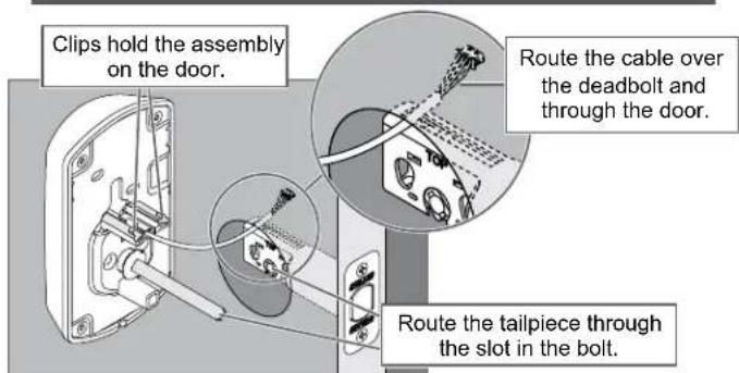
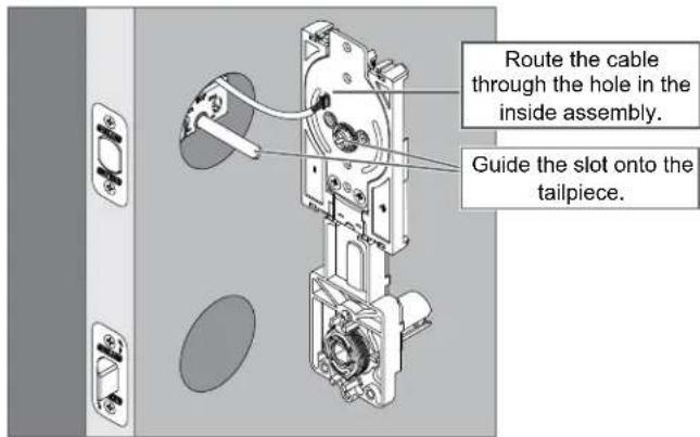
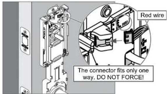
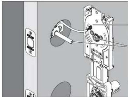
4 Apply power to the lock.
4a Connect the cable to the inside assembly.
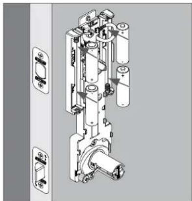
4b Install the batteries.
natural_image
Technical line drawing of a mechanical assembly with multiple components and mounting brackets (no text or symbols)5 Install the inside cover.
5a Place the inside cover on the door.
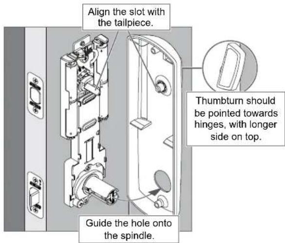
5b Secure the inside cover with two screws.
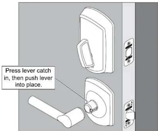
6 Install the levers.
6a Install the lever on the inside of the door.
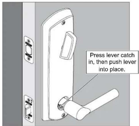
6b Install the lever on the outside of the door.
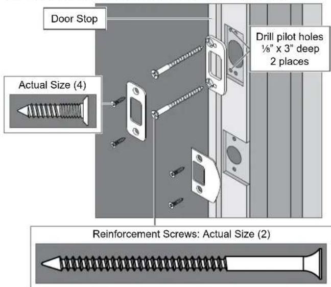
7 Install the strikes.
7a Install the strikes into the frame.
① Install all the parts shown for maximum security.
8 Test the lock.
8a Extend and then retract the bolt using the inside bolt throw.
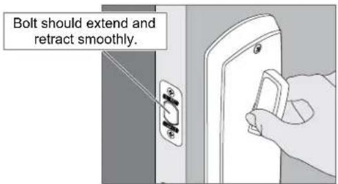
① Outside bolt throw should spin freely until a valid credential is presented.
8b Extend the bolt using the bolt throw and then rotate the inside lever.
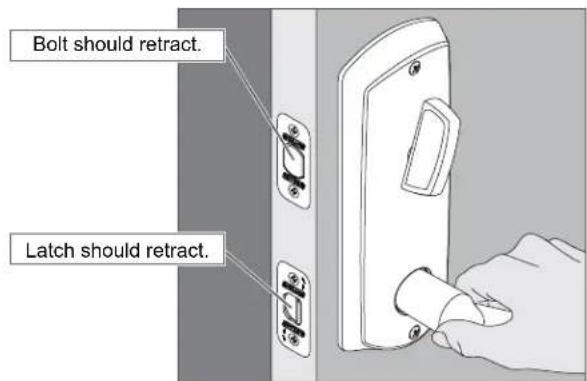
8c Rotate the outside lever.
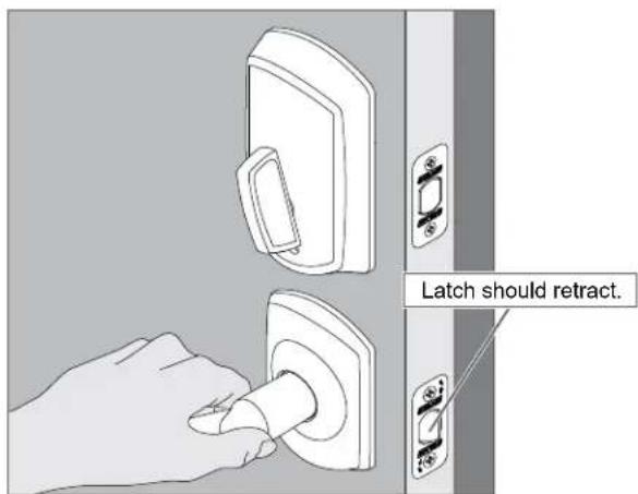
If the lock did not operate as described, please see Troubleshooting on page 8.
9 Set up the lock.
Continue to www.schlage.com to download the Schlage Control Smart Locks User Guide.
Troubleshooting
Most installation problems are related to handing. See Determine the Handing on page 2 to determine the hand of your door.
| Problem Solution Step | ||
| Inside lever will not rotate up. Lock is installed correctly. Inside lever should not rotate up. — | ||
| Inside lever rotates up. Inside lever should not rotate up. Check the handling. 3d, 3a, 2b | ||
| Inside lever will not rotate down. Check the handing. 3d, 3a, 2b | ||
| Rotating the inside lever down does not retract the latch. Check the handling. 3d, 3a, 2b | ||
| Outside lever will not rotate up. Lock is installed correctly. Outside lever should not rotate up. — | ||
| Outside lever rotates up. Outside lever should not rotate up. Check the handling. 3d, 3a, 2b | ||
| Outside lever will not rotate down. Check the handing. 3d, 3a, 2b | ||
| When in the locked state, rotating the outside lever unlocks the deadbolt without a valid credential being presented. | Check the handing. 3d, 3a, 2b | |
| Make sure the cam is in the correct position. 2c | ||
| When in the locked state, presenting a valid credential and rotating the outside thumbturn does not unlock the deadbolt. | Make sure the cam is in the correct position. 2c | |
| Make sure the batteries are installed correctly and are not dead. 4b | ||
| Make sure the cable is connected. | 4a | |
natural_image
Diagram showing a hand holding a tool interacting with a mechanical component, before and after transformation (no text or symbols)natural_image
Diagram showing two circular views of a vehicle interior with no visible text or symbols2d Instalar la unidad interna del lado interior de la puerta. Installez l'assemblage interne à l'intérieur de la porte.
① ¡El perno debe permanecer retraído!
① Le pêne doit demeurer rétracté!
natural_image
Mechanical assembly diagram showing a door lock mechanism with attached components and wiring (no text or symbols visible)natural_image
Technical illustration of a mechanical device with attached components and a close-up inset showing a threaded component (no text or symbols present)natural_image
Close-up of a standard threaded screw with a flat head and pointed tip (no text or symbols)natural_image
Technical illustration of a mechanical assembly with a flanged component and a separate view of a wall-mounted socket (no text or symbols)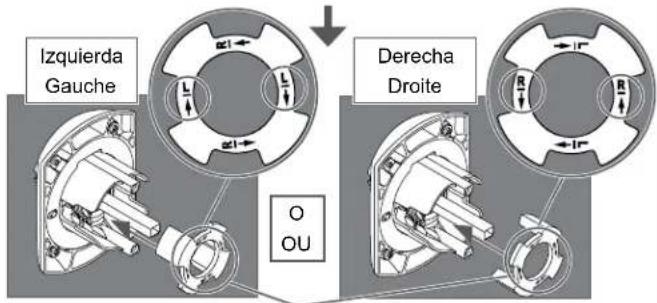
natural_image
Technical line drawing of a mechanical device with multiple cylindrical components and mounting brackets (no text or symbols)5 Instalar la tapa interna. Installez le couvercle interne.
5a Colocar la tapa interna en la puerta. Posez le couvercle interne sur la porte.
P517-266 Rev. 05/16-d2
BEGINNING SHEET
FOLDED SHEET
| Additional Notes: Revision History Revision Description: |
| 1. None A B C D E F |
| D2 > Revised artwork | |||||||||
| 061998 063431 065205 | |||||||||
| Material White Paper | Edited By Approved By EC | Number Release Date | |||||||
| M. Sasso P. Bockelman 065205 05-05-16 | |||||||||
| Notes1. folded booklet style2. saddle-stitched3. printed two sides4. printed black5. tolerance ± .136. printed in country may vary7. drawings not to scale | Title FE410 Installation Instructions | ||||||||
| Creation Date 03-27-2015 | Number P517-266 | Revision D2 | |||||||
| Created By M. Sasso | Activity 3899 Hancock Expwy Security, CO 80911 | © Allegion 2016 | |||||||
| Software: InDesign CS6 | |||||||||