Powerduction 160LG - Cooker GYS - Free user manual and instructions
Find the device manual for free Powerduction 160LG GYS in PDF.

User questions about Powerduction 160LG GYS
0 question about this device. Answer the ones you know or ask your own.
Ask a new question about this device
Download the instructions for your Cooker in PDF format for free! Find your manual Powerduction 160LG - GYS and take your electronic device back in hand. On this page are published all the documents necessary for the use of your device. Powerduction 160LG by GYS.
USER MANUAL Powerduction 160LG GYS
natural_image
Line drawing of three industrial electrical equipment units with wheels and vertical supports (no text or symbols)FR 2-9 / 10-22 / 101-112
EN 2-9 / 22-35 / 101-112
DE 2-9 / 35-48 / 101-112
ES 2-9 / 48-61 / 101-112
RU 2-9 / 61-74 / 101-112
NL 2-9 / 74-87 / 101-112
IT 2-9 / 87-100 / 101-112
POWERDUCTION
110LG
160LG
220LG
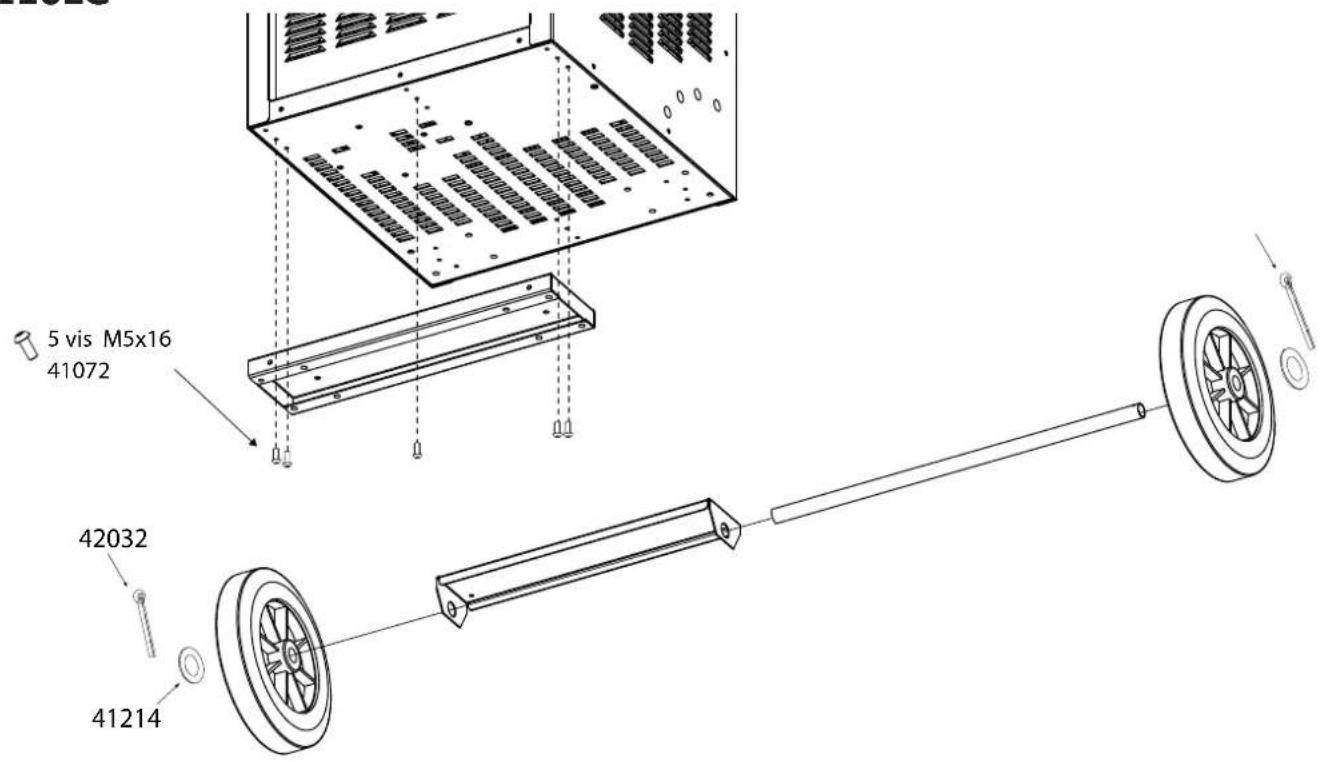
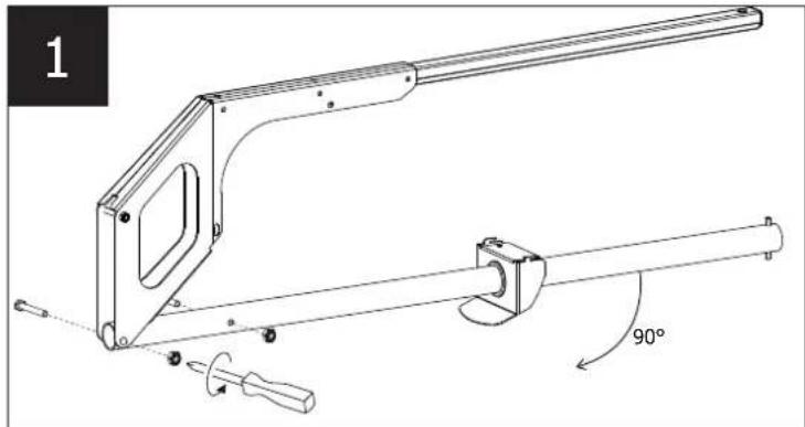
MONTAGE / MOUNTING / MONTAGE / MONTAJE / MOHTAK / MONTAGE / MONTAGGIO
110LG
text_image
5 vis M5x16 41072 42032 41214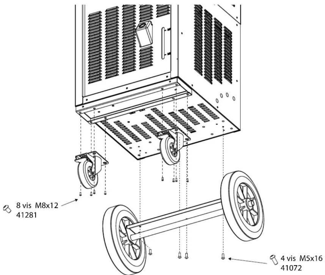
text_image
8 vis M8x12 41281 4 vis M5x16 41072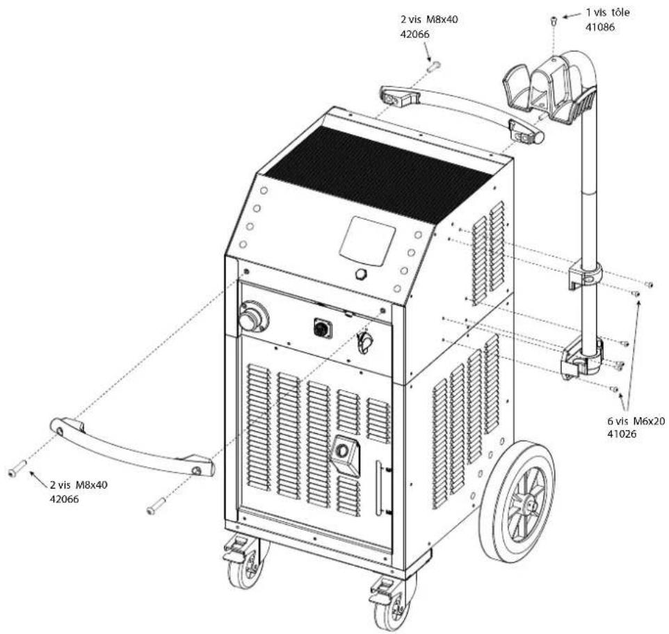
text_image
2 vis M8x40 42066 2 vis M8x40 42066 1 vis tôle 41086 6 vis M6x20 41026 2 vis M8x40 42066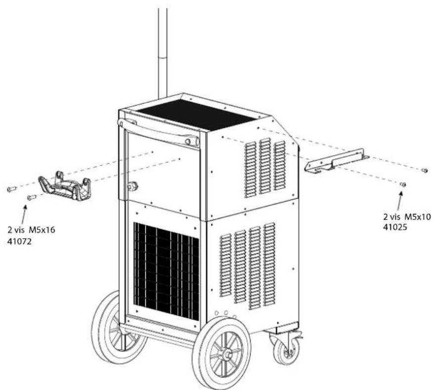
text_image
2 vis M5x16 41072 2 vis M5x10 41025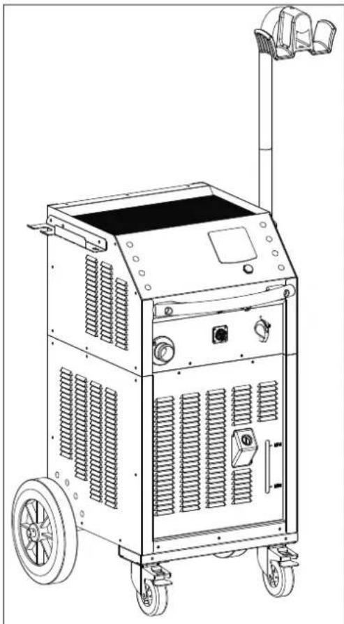
natural_image
Line drawing of a portable industrial machine with wheels and control panel (no text or symbols)160 LG / 220 LG
| Vis Screw | Vis Screw | Écrou frein Lock-nut |
| M8x20 M8x60 M8 | ||
| x 4 x2 x 2 | ||
natural_image
Technical line drawing of a mechanical lever assembly with 90-degree angle annotation (no text or symbols beyond label)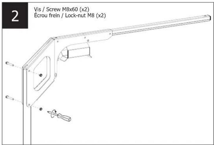
text_image
2 Vis / Screw M8x60 (x2) Écrou frein / Lock-nut M8 (x2)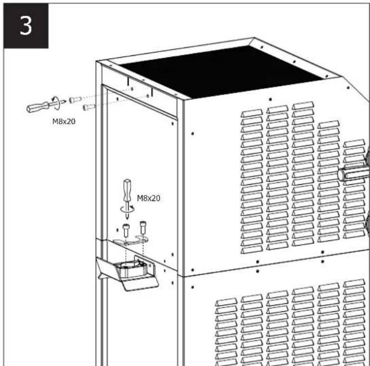
text_image
3 M8x20 M8x20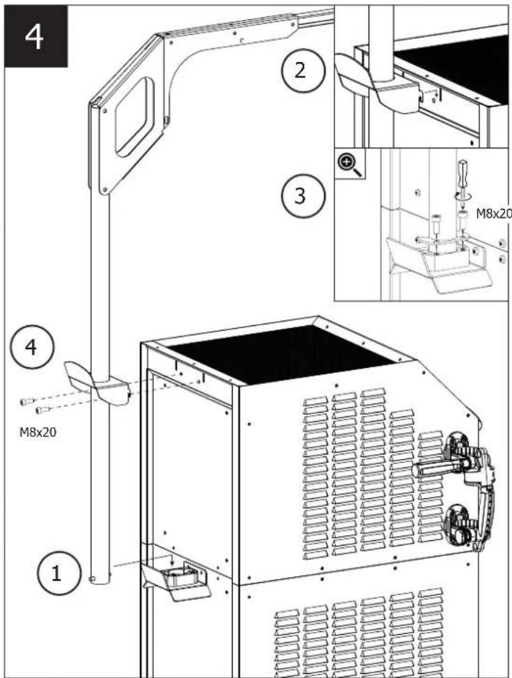
text_image
4 2 3 M8x20 1 4 M8x20
natural_image
Line drawing of a portable industrial machine with wheels and a handle (no text or symbols)Poignée amovible / Removable handle / Abnehmbarer Griff / Asa desmontable / Съемная ручка / Verwijderbaar handvat / Maniglia rimovibile
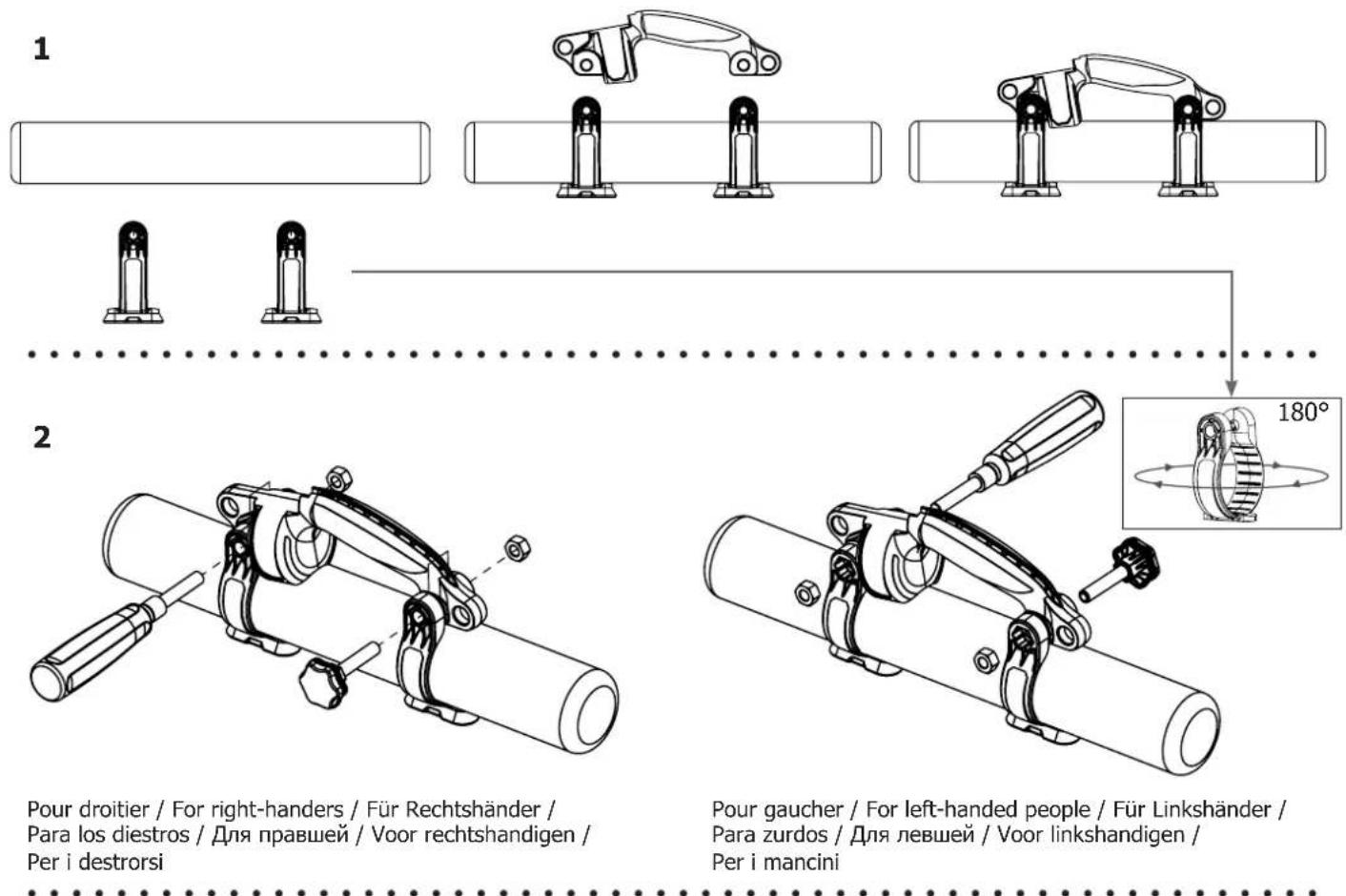
Pour droitier / For right-handers / Für Rechtshänder / Para los diestros / Для правшей / Voor rechtshandigen / Per i destrorsi
Pour gaucher / For left-handed people / Für Linkshänder / Para zurdos / Для левшей / Voor linkshandigen / Per i mancini
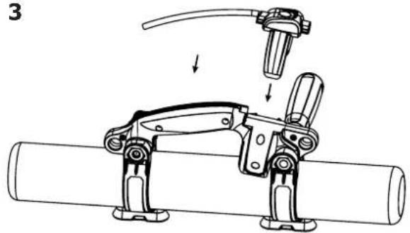
3
natural_image
Mechanical assembly diagram showing a tool interacting with a cylindrical pipe (no text or symbols present)4
natural_image
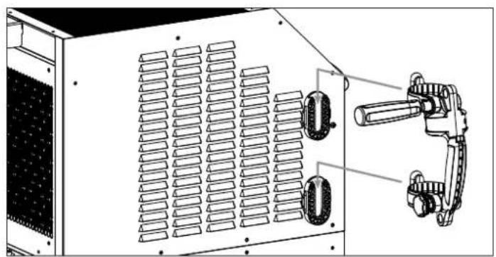
Technical line drawing of a server rack unit with ventilation grilles and mechanical clamps (no text or symbols)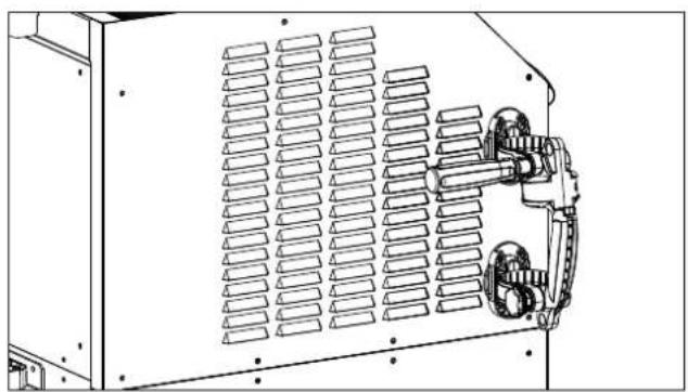
natural_image
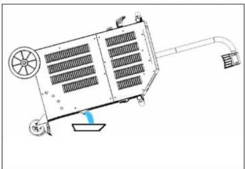
Technical line drawing of a mechanical or electrical enclosure with ventilation grilles and mounting brackets (no text or symbols)MISE EN EAU DU RÉSERVOIR / IMPOUNDMENT OF THE RESERVOIR / BEWÄSSERUNG DES SPEICHERS / RIEGO DEL EMBALSE / ЗАПОЛНЕНИЕ РЕЗЕРВУАРА / BEWATERING VAN HET RESERVOIR / IRRIGAZIONE DEL SERBATOIO
110LG

text_image
Diagram illustrating a medical device with labeled parts and directional arrows, including 'Press x 2' annotation.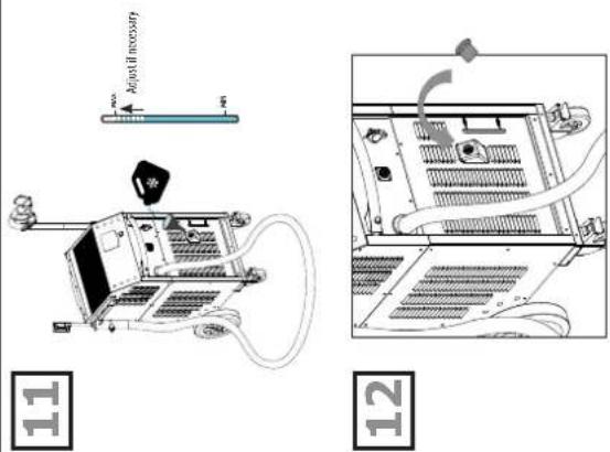
text_image
Adjust if necessary 11 12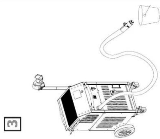
natural_image
Line drawing of a mechanical device with hoses and a bucket, no text or symbols present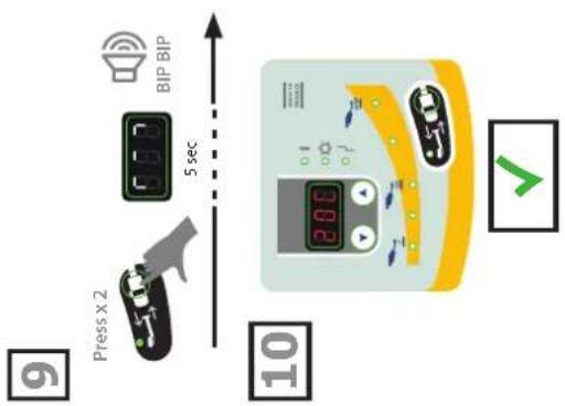
text_image
BIP BIP 5 sec Press x 2 10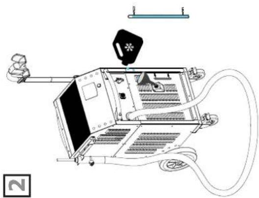
natural_image
Technical line drawing of a mechanical device with hoses and a central component (no text or symbols)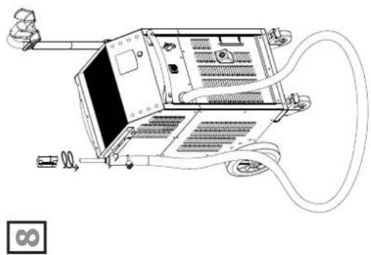
natural_image
Line drawing of a computer chassis with attached cables and connectors (no text or symbols)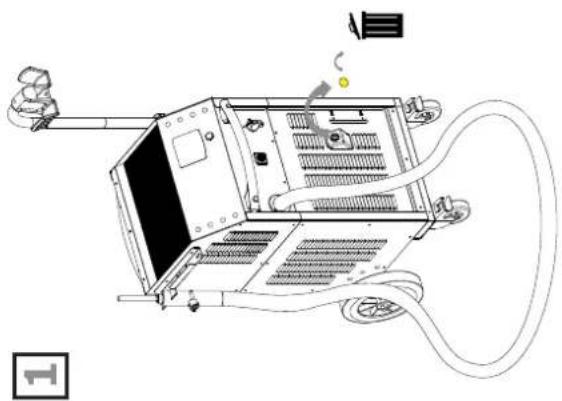
natural_image
Line drawing of a computer setup with monitor, keyboard, and cables (no text or symbols)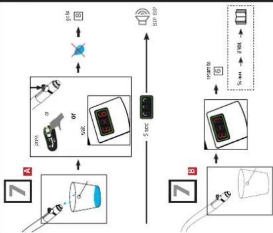
flowchart
graph TD
    A["7"] --> B["7"]
    B --> C["7"]
    C --> D["7"]
    D --> E["7"]
    E --> F["7"]
    F --> G["7"]
    G --> H["7"]
    H --> I["7"]
    I --> J["7"]
    J --> K["7"]
    K --> L["7"]
    L --> M["7"]
    M --> N["7"]
    N --> O["7"]
    O --> P["7"]
    P --> Q["7"]
    Q --> R["7"]
    R --> S["7"]
    S --> T["7"]
    T --> U["7"]
    U --> V["7"]
    V --> W["7"]
    W --> X["7"]
    X --> Y["7"]
    Y --> Z["7"]
    Z --> AA["7"]
    AA --> AB["7"]
    AB --> AC["7"]
    AC --> AD["7"]
    AD --> AE["7"]
    AE --> AF["7"]
    AF --> AG["7"]
    AG --> AH["7"]
    AH --> AI["7"]
    AI --> AJ["7"]
    AJ --> AK["7"]
    AK --> AL["7"]
    AL --> AM["7"]
    AM --> AN["7"]
    AN --> AO["7"]
    AO --> AP["7"]
    AP --> AQ["7"]
    AQ --> AR["7"]
    AR --> AS["7"]
    AS --> AT["7"]
    AT --> AU["7"]
    AU --> AV["7"]
    AV --> AW["7"]
    AW --> AX["7"]
    AX --> AY["7"]
    AY --> AZ["7"]
    AZ --> BA["7"]
    BA --> BB["7"]
    BB --> BC["7"]
    BC --> BD["7"]
    BD --> BE["7"]
    BE --> BF["7"]
    BF --> BG["7"]
    BG --> BH["7"]
    BH --> BI["7"]
    BI --> BJ["7"]
    BJ --> BK["7"]
    BK --> BL["7"]
    BL --> BM["7"]
    BM --> BN["7"]
    BN --> BO["7"]
    BO --> BP["7"]
    BP --> BQ["7"]
    BQ --> BR["7"]
    BR --> BS["7"]
    BS --> BT["7"]
    BT --> BU["7"]
    BU --> BV["7"]
    BV --> BW["7"]
    BW --> BX["7"]
    BX --> BY["7"]
    BY --> BZ["7"]
160LG / 220LG
text_image
Diagram illustrating vehicle charging process with icons and labeled steps 4, 5, 6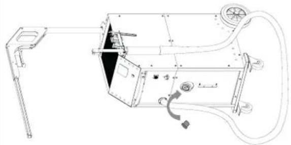
natural_image
Technical line drawing of a mechanical device with no visible text or symbols
natural_image
Technical line drawing of a mechanical device with hoses and components (no text or symbols)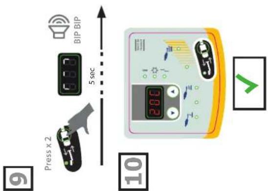
text_image
BIP BIP 5 sec Press x 2 10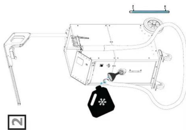
natural_image
Technical line drawing of a mechanical device with attached components and a black bag (no text or symbols)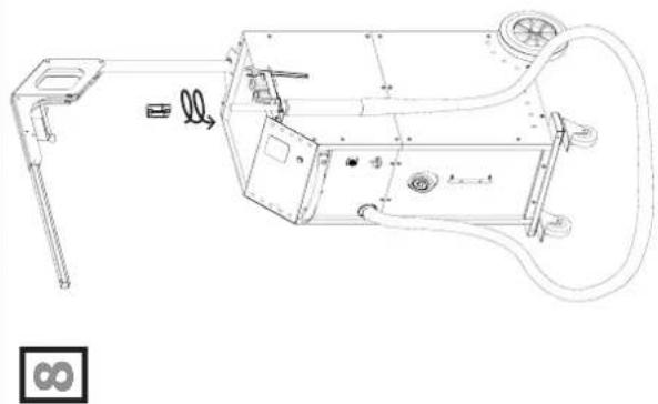
natural_image
Technical line drawing of a mechanical device with exploded view and internal components (no text or symbols)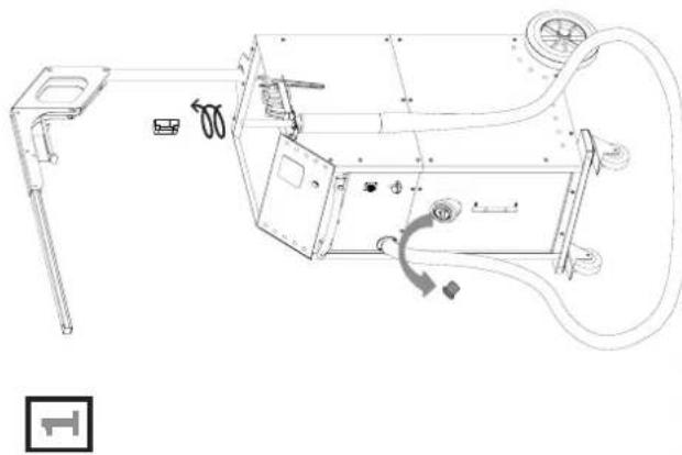
natural_image
Technical line drawing of a mechanical device with exploded view and internal components (no text or symbols)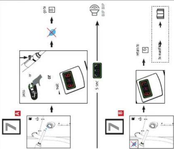
flowchart
graph TD
    A["Car"] -->|go to| B["BIP BIP"]
    B --> C["Sensor"]
    C --> D["5 sec"]
    D --> E["Return to"]
    E --> F["Car"]
    F --> G["Sensor"]
    G --> H["5 sec"]
    H --> I["Display"]
    style A fill:#f9f,stroke:#333
    style B fill:#ccf,stroke:#333
    style C fill:#cfc,stroke:#333
    style D fill:#fcc,stroke:#333
    style E fill:#cff,stroke:#333
    style F fill:#ffc,stroke:#333
    style G fill:#cfc,stroke:#333
    style H fill:#fcc,stroke:#333
I
text_image
POWERDUCTION 160LG 17 18 2 15 12 11 GYS 19 1 110 LG 208-240 V 18 17 GYS 208-240 V 75352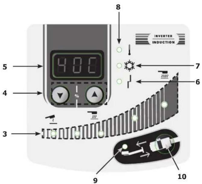
text_image
4.00 5 4 3 8 INVERTER INDUCTION 7 6 9 10- Ne pas tordre la lance !
- Do not twist the lance!
- Den Speer nicht knicken!
- iNo retuerzas la lanza!
- Verdraai de speer niet!
- Non torcere la lancia!
text_image
20 - Verdural de spect met: - Non torcere la lancia!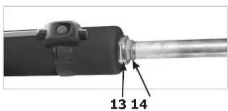
text_image
13 14II
Réaction des témoins lumineux / Reaction of the indicator lights / Reaktion der Kontrollleuchten / Reacción de las luces indicadoras / Реакция световых приборов / Reactie van de indicatielampjes / Reazione delle spie luminose
natural_image
Diagram showing a curved surface with vertical stripes and circular markers, no text or symbols present| État du voyant / Indicator status / Indikatorstatus / Estado del indicador / Состояние индикатора / Indicatorstatus / Stato dell'indicatore | |
| Allumé / Light on / Licht an / Luz encendida / Горит / Oplichten / Luce accesa | |
| Clignote lentement / Flashing slowly / Blinkt langsam / Parpadea lentamente / мигает медленно / Knippert langzaam / Lampeggia lentamente | |
| Clignote rapidement / Flashing quickly / Blinkt schnell / Parpadea rápidamente / Мигает быстро / knippert snel / Lampeggia rapidamente | |
| Éteint / Off / Aus / Apagado / Выключен / Uit / Spento | |
| % | Puissance (W) / Power (W) / Leistung (W) / Potencia (W) / Мощность (W) / Vermogen (W) / Potenza (W) | |||||||
| 110 LG 160 LG 220LG | ||||||||
| 10 1,1 kW | 1,6 kW 2,2 kW | |||||||
| 20 2,2 kW | 3,2 kW 4,4 kW | |||||||
| 30 3,3 kW | 4,8 kW 6,6 kW | |||||||
| 40 4,4 kW | 6,4 kW 8,8 kW | |||||||
| 50 5,5 kW | 8 kW 11 kW | |||||||
| 60 6,6 kW | 9,6 kW 13,2 kW | |||||||
| 70 7,7 kW | 11,2 kW 15,4 kW | |||||||
| 80 8,8 kW | 12,8 kW 17,6 kW | |||||||
| 90 9,9 kW | 14,4 kW 19,8 kW | |||||||
| 100 11 kW | 16 kW 22 kW | |||||||
| Hi 11 kW | 16 kW 22 kW | |||||||
text_image
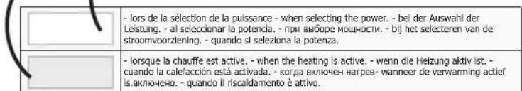
- lors de la sélection de la puissance - when selecting the power. - bei der Auswahl der Leistung. - al seleccionar la potencia. - при выборе мощности. - bij het selecteren van de stroomvoorziening. - quando si seleziona la potenza. - lorsque la chauffe est active, - when the heating is active, - wenn die Heizung aktiv ist. - cuando la calefacción está activada. - когда включен нагрев- wanneer de verwarming actief is, vключено. - quando il riscaldamento è attivo.CONSIGNE GÉNÉRALE

SPÉCIFICATIONS DU PRODUIT
110LG 160LG 220LG
natural_image
Hand interacting with a black electronic device, showing a green arrow and a green square (no text or symbols)MODE «TEMPORISATION»\*
natural_image
Close-up of a black industrial tool with a metallic shaft and cylindrical component (no visible text or symbols)Couple de serrage max = 7 Nm
natural_image
Mechanical device with numbered components and a circular motion indicator (no visible text or symbols)natural_image
Technical line drawing of a mechanical device with labeled component '110 LG' (no other text or symbols)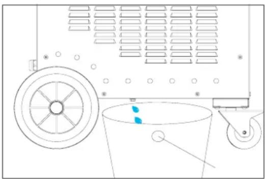
natural_image
Technical line drawing of a mechanical device with pulley, bucket, and wheel (no text or symbols)natural_image
Close-up of a mechanical component with a 7 Nm scale indicator (no text or symbols on the object itself)CONDITIONS DE GARANTIE
This manual contains safety and operating instructions.
Please read it carefully before using the device for the first time and keep it for future reference.
Read and understand the following safety instructions before use.
Any modification or updates that are not specified in the instruction's manual should not be undertaken.
The manufacturer is not liable for any injury or damage due to non-compliance with the instructions featured in this manual.
If there is any issue or uncertainty, please consult a qualified individual to operate the equipment correctly.
This machine should only be used for heating ferrous materials within the limits indicated on the machine and in the instruction manual. The operator must observe the safety precautions. In case of improper or unsafe use, the manufacturer cannot be held liable.
ENVIRONMENT
Operating temperature:
Use between -10 and +40°C (+14 and +104°F).
Store between -25 and +55°C (-13 and 131°F).
Air humidity:
Lower or equal to 50% at 40°C (104°F).
Lower or equal to 90% at 20°C (68°F).
Altitude:
Up to 1000 meters above sea level (3280 feet).
INDIVIDUAL PROTECTION & OTHERS
Induction heating can be dangerous and cause serious injury or death.
Induction heating exposes people to a source of heat, electromagnetic fields and light radiation that can be dangerous.
To protect oneself as well as others, ensure the following safety precautions are taken:


- To protect yourself from optical radiation and metal splashes, use a helmet or protective goggles with shade 5.
- In order to protect you from burns and radiations, wear clothing without turn-up or cuffs. These clothes must be insulating, dry, fireproof, in good condition and cover the whole body.
- Do not wear clothing with metal fasteners, metal buttons, or metal covers of any kind.
- Wear protective gloves which guarantee electrical and thermal insulation.
- Not for use by pacemaker users.
- People wearing pacemakers are advised to not come close to the machine.
- Risk of disruption of pacemaker operations when close to the machine.
- Entry prohibited for holders of metal implants
- People wearing pacemakers are advised to not come close to the machine.
- Make sure that jewellery (especially wedding rings) or metal parts (keys, watch) do not come near the induction system and inductor during operation.
- Remove all jewellery and other metal objects from your body before using this equipment
RISK OF BURNS

Induction heating increases the temperature of the metal very quickly!
- Do not touch hot parts or the inductor with bare hands.
- Wait for the parts and pieces to cool down before handling them.
- In case of burn, rince thoroughly with water and consult a doctor as soon as possible.
FIRE AND EXPLOSION RISKS


- Do not position the machine on, or near flammable surfaces
- Do not position the machine near flammable materials.
- Do not heat containers, vessels or pipes that contain or have contained flammable liquids or gases.
-
Do not overheat parts and adhesives.
-
In case of fire, use a fire extinguisher or fire blanket.
- Do not use the device in an explosive atmosphere.
- Do not heat pressurised containers.
- Keep airbags, gas cannisters or other pressurised gas containers away from the induction heating machine.»
VAPOUR AND GAS RISK
- Keep the head away from the fumes, do not inhale.
- If working inside, ventilate the area or use a fume extractor to evacuate the gases and fumes.
- Induction heating of certain materials such as adhesives and flux can generate fumes and gases. Breathing these fumes and gases can be dangerous for your health. For example, heating urethane generates a gas: hydrogen cyanide, potentially mortal for humans.
- If the ventilation is insufficient, use an approved respiratory unit.
- Read the safety data sheets (MSDS) and the manufacturer's instructions for adhesives, flux, metals, consumables, coatings, cleaning agents, corrosives, and paint strippers.
- Work in a confined area only if it's well ventilated, or use an approved respiratory/filtration unit. Make sure that a qualified person is around to watch over you. The fumes and gases released while heating can replace oxygen or air, causing accidents or death. Check the quality of the air you're breathing
- Do not use the heater on parts being degreased or sprayed. The heat might react with fumes and generate highly toxic gases.
- Do not overheat metals, such as galvanised steel, covered with lead or cadmium, unless the coating is removed from the surface before it's heated, that the area is well ventilated, and if needed, use an approved filtration/respiratory unit. Foundry pieces and all metals containing such elements may generate toxic fumes if overheated.
Check the MSDS for temperature related details.
ELECTROMAGNETIC FIELD EMISSIONS


- During operation, the inductor generates strong electromagnetic fields that are not visible.
- The equipment has been designed to minimise the risks from electromagnetic fields, however residual risks remain.
- Maintain a minimum safety distance of 30 cm between the inductor and the operator's head or torso.
- The inductor must be aimed exclusively at the metal parts to be heated.
- Never wrap the cables around the body.
OPTICAL RADIATIONS

- Risk of optical emission when heated metal elements approach and approach and reach fusion.
- Optical radiation can be harmful to the eyes and skin.
ELECTRICAL RISK

An electric shock could cause serious injuries or potentially even deadly accidents.

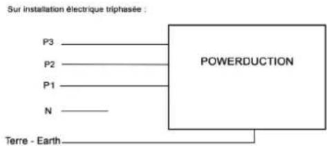
| 110LG / 160LG / 220LG400 V | The appliance is class I and should only be used on a 3-phase 400V (50/60 Hz) four-wire electrical installation with a neutral conductor connected to earth. |
| 110LG / 160LGUL Standard | The appliance is class I and should only be used on a 3-phase 208-240V (50/60 Hz) four-wire electrical installation with a neutral conductor connected to earth. |
- The maximum absorbed current (I1) is indicated on the equipment for the maximum operating conditions. Check that the power supply and its protection (fuse and/or circuit breaker) are compatible with the current needed by the machine.
- The maximum absorbed current (I1) is indicated on the equipment for the maximum operating conditions.
- Do not use the appliance if the power cable, the mains plug or the lance are damaged.
- Do not use the inductor in the rain or on wet or submerged parts.»
EMC CLASSIFICATION

220LG only
- These Class A devices are not intended to be used on a residential site where the electric current is supplied by the public network, with a low voltage power supply. There may be potential difficulties in ensuring electromagnetic compatibility at these sites, due to conducted interferences as well as radiation.
- This equipment complies with IEC 61000-3-12, provided that the power of the short-circuit Ssc is equal to or greater than 7.6 MVA at the interface between the machine and the mains power network.
- It is the responsibility of the installer or user of the equipment to ensure if necessary by consulting the operator of the mains electricity, that the equipment is only connected to a power supply where the power of short-circuit ssc is equal to or greater than 2.8MVA.
- This equipment does not comply with IEC 61000-3-12 and is intended to be connected to domestic low-voltage systems interfacing with the public supply only at the medium- or high-voltage level. If connected to a public low-voltage power grid, the installer or user of the machine has to ensure, by checking with the network operator, that the device can be connected.
- This equipment complies with the IEC 61000-3-11 standard.
MAINTENANCE / RECOMMENDATIONS

- Maintenance should only be carried out by a qualified person. A yearly maintenance is recommended.
- Warning ! Always disconnect from the mains before performing maintenance on the device. High Voltage and currents inside the machine.
- Remove the casing on a regular basis, to remove any excess dust. Take this opportunity to have the electrical connections checked by a qualified person, using an insulated tool.
- Do not use solvents or any agressive cleaning products.
-
Clean the device's surfaces with a dry cloth.
-
If the power cable or connection cables are damaged, they must be replaced by the manufacturer, its after sales service or an equally qualified person to prevent danger.
- If the internal fuse is melted, it must be replaced by the manufacturer, its after-sales service or by an equally qualified person to prevent any accidents.»
- Do not obstruct the machine's air intake, which facilitates air circulation. Check the installation chapter before using the device.
- Maintain at least 50 cm of free space around the equipment.
TRANSPORT
- Do not use the power cable or nozzle to move the unit. It must be moved in a vertical position.
- The handle cannot be used to lift the product.
REGULATIONS
• The device complies with the European directives,
- The declaration of conformity is available on our website (see cover page).
• EAC conformity mark (Eurasian Economic Commission)
- Material conforms to UK requirements.
- The UK Declaration of Conformity is available on our website (see cover page).
• Device compliant with Moroccan standards.
- The C_ (CMIM) declaration of conformity is available on our website.
WASTE MANAGEMENT

- This product should be disposed of in an appropriate recycling facility. Do not throw away in a household bin.
• This product should be recycled appropriately
• Recyclable product that falls within waste sorting recommendations
PRODUCT IDENTIFICATION
At the back of the product, there is an identification plate that contains the following information:
- Name and address of the manufacturer
• Date of manufacture - Model
- Product Type
- Operating Voltage
This data must be specified for each maintenance intervention, or if spare parts are requested.
PRODUCT SPECIFICATIONS
| 110LG 160LG 220LG | |||||
| Rated input voltage 208-240 V 400 V 208-240 V 400 V | |||||
| Rated frequency 50 Hz - 60 Hz | |||||
| Number of conductors 3 Phases + Ground | |||||
| Rated input current 32 A 16 A 45 A 29 A 32 A | |||||
| Rated input power 11 000 W 16 000 W 22 000 W | |||||
| Processing frequency | 20-60 kHz microprocessor controlled. | ||||
| Rated output power 5 500 W | 8 000 W | 11 000 W | |||
| Length of power cable | 5 m | 4 m | |||
| Length of lance | 4 m | 6 m | 6 m / 10 m | ||
| Tank capacity | 7 litres | 30 litres | |||
| Coolant | Special welding liquid coolant (ref. 052246) | ||||
| Protection class | IP 21 | ||||
| Dimensions (cm) | 88 x 60 x 60 cm | 118 x 80 x 60 | |||
| Weight (kg) | 86 | 80 | 146 | 136 | 141 |
| Internal fuse | T5A - 250VAC - 6.3x32 | T2.5A - 500VAC - 6.3x32 | T5A - 250VAC - 6.3x32 | T2.5A - 500VAC - 6.3x32 | |
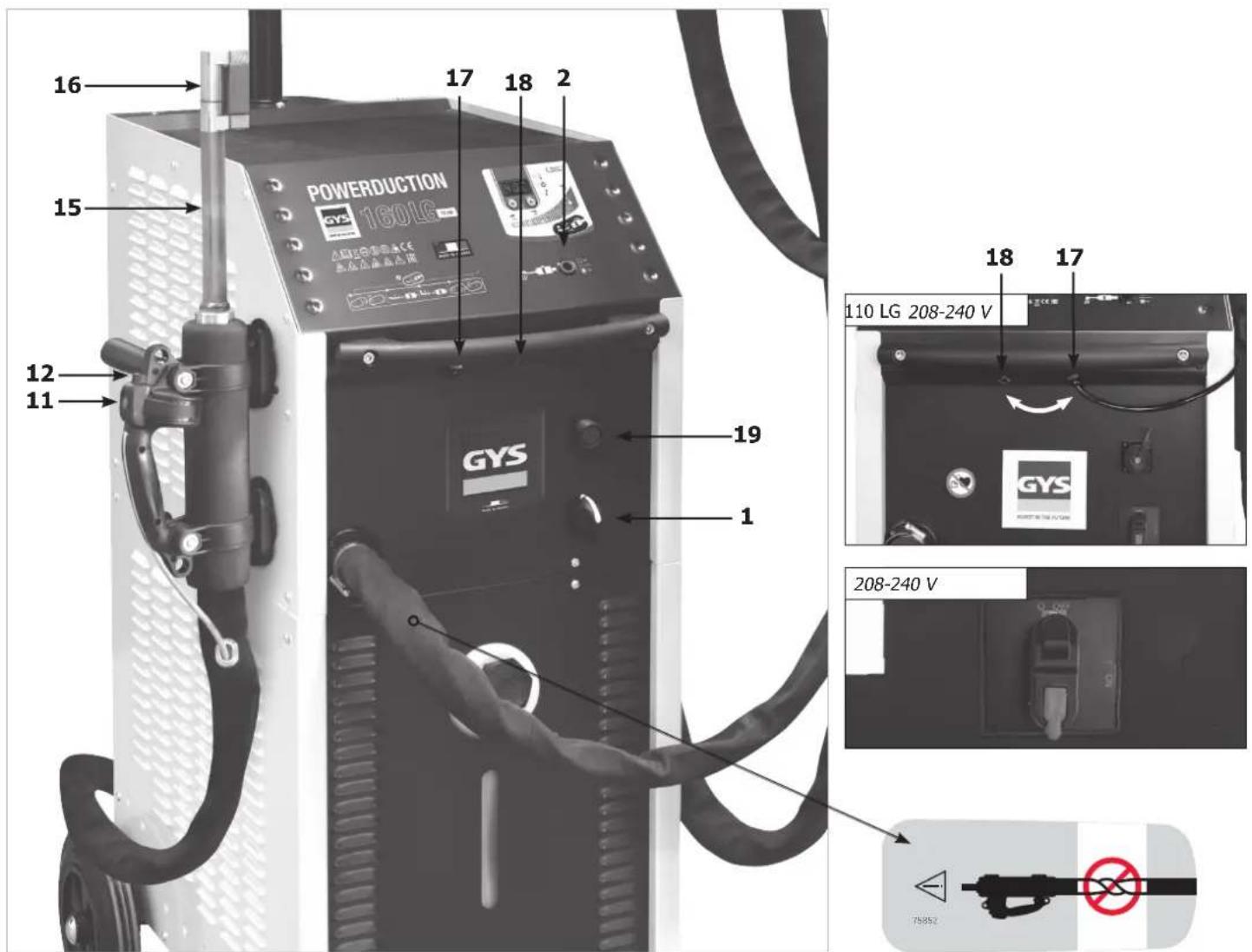
DESCRIPTION OF THE MACHINE (FIG I)
| 1 | Heat authorisation illuminated button |
| 2 | Main switch |
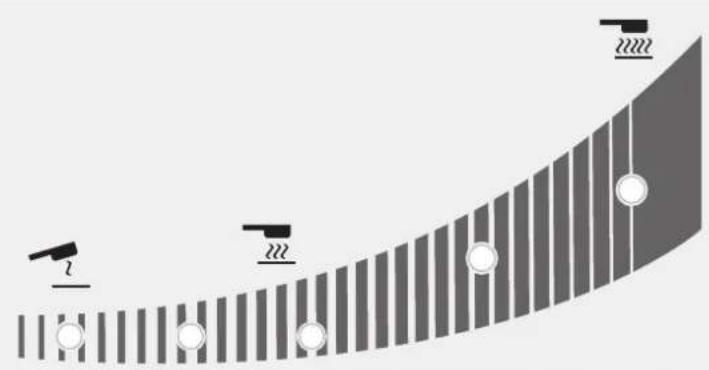
| 3 | Heating power indicator (110LG : 1 kW – 11 kW, 160LG : 1 kW – 16 kW 220LG : 2 kW – 22 kW). |
| 4 | Heating power settings or temperature unit button |
| 5 | Cooling liquid temperature |
| 6 | Inductor or machine fault indicator |
| 7 | Cooling circuit warning alarm indicator |
| 8 | Machine or cooling circuit thermal protection indicator |
| 9 | Inductor change indicator |
| 10 | Inductor change mode activation button |
| 11 | Lance button : start the heat |
| 12 | LED worklight (illuminates the heating point) |
| 13 | Lance attachment. For a 36 mm spanner |
| 14 | Adapter attachment : 27 mm spanner |
| 15 | Adaptor |
| 16 | Inductor |
| 17 | Pneumatic pedal connection |
| 18 | USB reprogramming socket |
| 19 | Outdoor temperature control connector (160LG) |
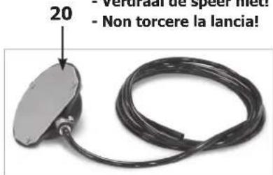
| 20 | Pneumatic pedal |
FIRST USE
The POWERDUCTION 110LG (except 208-240V) is supplied with a 5 m power cable fitted with a 16A, 5-pin, earthed plug. The POWERDUCTION 160LG / 220LG (except 208-240V) is supplied with an 4 m power cable fitted with a 32A, 5-pole earthed plug.
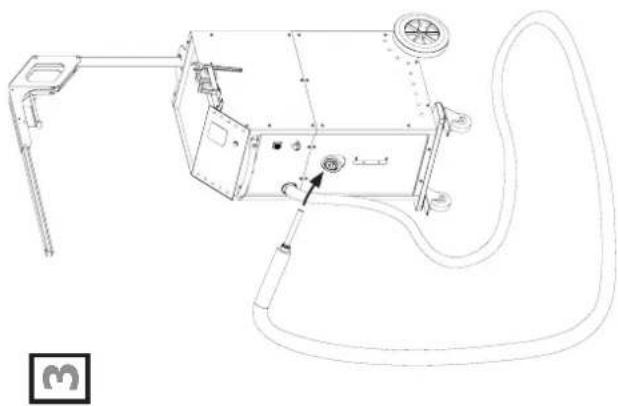
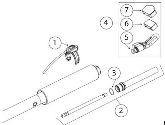
- Once the product is assembled, place the torch on its support. Unscrew the inductor and the tank's cap.
- Fill up the tank to the maximum using special welding liquid coolant (30 l / 7 l).
- Take the lance and place it at the tank inlet or above the filling canister.
- Connect the machine to the mains. Switch on the machine (1).
- The machine starts and will systematically display Error 6 or 7 («E-6» or «E-7»).
- Press the accessory change button (10) twice. The purge cycle takes 5 seconds (a loading icon should be displayed during it) and a double «beep» sound indicates completion.
- As soon as the liquid is coming out of the torch, stop the torch by pressing the torch button, the accessory change button or the heat authorisation button. Or wait for «E-6» to be displayed. If Error 7 is displayed, start again from step 6 (five times max, see default E-7 explanation).
- Screw the inductor by hand.
- Press the accessory change button (10) twice. The purge cycle takes 5 seconds (a loading icon should be displayed during it) and a double «beep» sound indicates completion.
- The temperature of the cooling liquid and the power instruction are displayed.
- Top up the tank with cooling liquid if required.
- Replace the tank cap. The product is ready to operate.
Solving fault E-7
If the issue remains, check that the pump is working correctly or that the pipe is not blocked.
After five unsuccessful purge cycles, it is possible to:
- Stretch the torch above the machine to clear any pocket of water and for the pump to kick in.
- Put the machine at a 30^ angle towards the torch.
- It is possible to blow the torch. Use an air blower and a cloth to keep it water proof and avoid projections.
- Re-attempt one or two cycles after each action.
If the issue remains, check that the pump is working correctly or that the pipe is not blocked.
INSTRUCTIONS
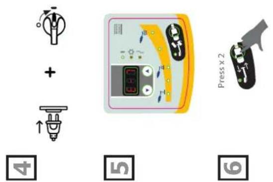
- Set the main switch (1) to ON.
The machine initialises in 2 seconds. - Press the heat authorisation button (2) as described on page 7. The indicator on button (2) and the lance support LED (12) both switch on, indicating that the machine is ready to operate.
- Position the inductor (13) flat on the workpiece (place the open part of the ferrite towards the workpiece).
- Press the button (11) on the lance or the pneumatic pedal to start the heating; if necessary move the inductor to heat a larger area. Two indicators indicate that the heating is active:
- The brightness of the LED illuminating the inductor (12) decreases*.
- The minimum power indicator light on the heating power indicator (3) flashes quickly (in HI mode both min & max lights flash).

Do not heat the same area for too long (a few seconds are sufficient depending on the thickness) to prevent the metal piece from melting.
It is possible to change the rated power during the heating.

The heating set point can be set to Hi. The power is identical to the 100% mode but the Powerduction behaves differently:
- At 100%: he wears the part red and maintains the right power for a few seconds before slowly reaching its maximum power.
- In Hi mode: it rises to its maximum power regardless of the condition of the room to be heated. Remain very vigilant, the heating is strong and fast and may damage the part without a control of this mode.
The display provides a continuous update of the cooling liquid temperature (max 60°C/140°F).
- During the powering up phase, the pump and the cooling fan activate for a few seconds, to check that they are working properly.
- After the heating stops, let the cooling circuit operate to cool down the inductor, before switching off the machine.
- To modify the cooling liquid temperature unit, press and hold both settings buttons (4) until the desired unit is displayed (" -F-" = Farenheit / " -C-" = Celsius). Release the buttons, the change is saved and in effect.

The machine has been designed to minimise the risks due to electromagnetic fields. Some residual risks persist and it is recommended to observe a security distance between the inductor and the operator's head/torso.
Heat on standby
For security reasons, the product deactivates the heat authorisation after 5 minutes of inactivity. The heat authorisation button indicator and the lance support LED both switch off.
To reactivate the machine, press the heat authorisation button (2) or press and hold the lance button (11) for 1 second. This feature is disabled after 20 minutes of inactivity.
It allows the user to stay in a working position without the need to reach for the machine.
INDUCTOR PRESERVATION
The heated metal radiates heat on to the inductor at the square of the temperature to which it is heated. The inductor is therefore highly exposed. When the metal is dark red, the temperature is below 850^ C. If it turns bright red/orange, the temperature exceeds 1000^ C. If it turns white, the temperature exceeds 1200^ C
(the chart below is available in colour on the website manual).
600 °C 900 °C 1300 °C
To preserve the inductor and extend its life, it is necessary to keep the temperature around 850^ C as much as possible and avoid prolonged use.
The ferrite included in the inductor has a higher coefficient of expansion than its mechanical support. Excessive heating of the inductor causes distortion to the ferrite. It is up to the user to avoid this excessive heating.

Therefore, the inductor, or ferrite when they are removable, are consumables to which the warranty does not apply.
WARNING LIGHTS
- The indicator 6 signals a machine/inductor fault.
- The indicator 7 signals a cooling circuit liquid flow fault.
- The indicator 8 signals a thermal protection of the power block or the excessive temperature of the cooling liquid which is 60^ C/140°F.
Wait for the indicator to switch off and the machine is ready to operate.
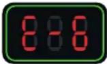
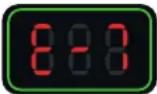
The display 5 displays the fault code :
| Fault code Cause | ||
| E - 1 Heat | authorisation button (2) is stuck. In short-circuit or mechanically blocked. | |
| E - 2 Lance | button (11) is stuck. In short-circuit or mechanically blocked. | |
| E - 3 Keypad | buttons are stuck (9) and (11). In short-circuit or mechanically blocked. | |
| E - 4* | Inductor intensity is too high or not compatible. | Faulty lance or inductor in short circuit. |
| E - 5* | inductor intensity is too low. Inductor is not screwed properly or faulty lance. | |
| E - 6 | Flow is too high >6 l/min. | Pierced hose or missing inductor. |
| E - 7 Flow | too low <4 l/min. | Hose is pinched or obstructed, the pump does not operate. |
| E - 8* | Internal fault. Disconnected flat command cable. | |
| E - 9 Voltage | network fault. The network voltage is too low. | |
| E - 10 Power-up fault | Pneumatic pedal active when powered up. | |
| E - 11 | Regulation temperature measurement fault | The temperature sensor is off or short-circuit. |
| E - 12 | The temperature does not change during heating | Incorrectly positioned temperature sensor. |
| E - 13 Power relay fault. Connection cable unplugged. | ||
| E - 14 Power-up fault | The pneumatic foot pedal is active at power-up when the Powerduction Heat Controller is connected to the product. | |
| --- | Overvoltage fault. | Voltage above 460 V sector. |
| + | No phase | Disconnected phase in socket / product or fuse / switch off |
*In the case of faults E-4, E-5 and E-8, restart the product after correcting the fault.
| Fault code E5Inductor screwing problem :(check screwing, be careful not to overtighten!) | Fault code E6Flow rate fault refer to pages 6, 7 & 13 | Fault code E7Flow rate fault refer to pages 6, 7 & 13 |
 |  |  |
NB : In the event of a warning alarm, the machine does not work.
The machine is fitted with several protect ion systems against electrical overcharge and cooling faults.
The thermal protection mostly activates when heating stainless steel, aluminium and copper parts. To reactivate the machine, simply wait for the cooling phase to end. For other protections, switch off the machine using the main switch and switch it back on. For fault alarms E-6 and E-7, check that there is no leak or an obstructed/broken hose, that the pump is not blocked or deactivated and that there is enough cooling liquid in the tank.
If the problem appears to have been rectified, press the «inductor change» button twice (10). The cooling circuit is performing a purge cycle. It is ready to operate.
Press x 2
natural_image
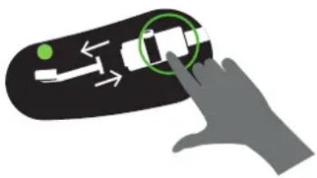
Hand interacting with a device on a black surface, showing a green dot and directional arrows (no text or symbols)TIME DELAY MODE\*
The "Timing" function allows you to control the heating time of the Powerduction.
The time is adjustable from 1 to 30 s.* (Time adjustable from 1 to 120 s from Soft V6.50 version)*.
To enter this mode:
-
Press the heating authorization button (2). Its indicator light comes on.
-
Then press both power adjustment buttons (4) simultaneously. The display shows "SEC" then "T 00" or "SEC" then "ON" if a time has already been set.
-
The power setting buttons (4) become time setting buttons. Change the setpoint from time to time as desired.
⚠️ If the time value has not been changed beyond 3 seconds and still shows "T 00", the Powerduction returns to normal mode.
Use in "Timer" mode:
Once the time setpoint has been selected, the product is ready for operation. The lighting LED (12) is lit.
-
Press the lance button (11). The intensity of the LED (12) decreases to indicate that the heating is active.
-
The heating stops at the end of the time limit. As long as the lance button (11) is pressed, the LED (12) and the heating enable button (2) flash to warn that the power is off. Adjust the time setpoint if necessary.
-
Press the lance button (11) for a new heating cycle.
Exit the "Timer" mode
The mode remains active at all times, even when the Powerduction is switched off and then on again.
- To exit the mode, set the time setpoint on or press both power control buttons (4) simultaneously. The Powerduction returns to normal operating mode. The display shows "SEC" then "OFF".
Special feature of the power setting in this mode
As explained, in normal use mode the setting buttons allow you to change the power while in this mode they change the time setpoint. To change the power without leaving the mode:
-
Press the heating authorization button (2). Its green light goes out.
-
The setting buttons (4) allow you to change the power. Adjust the power.
-
Press button (2) again. Its indicator light comes on again. The setting buttons (4) become the time setting again.
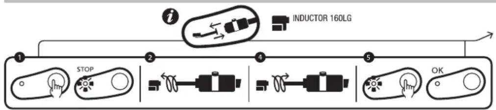
«ACCESSORY CHANGE» MODE
flowchart
graph LR
    A["1 STOP"] --> B["2 Inductor 160LG"]
    B --> C["4"]
    C --> D["5 OK"]
product serigraphy
natural_image
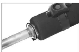
Close-up of a mechanical tool or component with a metallic shaft and black housing (no visible text or symbols)Tightening torque max = 7N
This mode is accessible only if the heating isn't activated (green button switched off).
- Press the button (10), the pump stops and the LED (9) switches on.
- Place the lance on its supports and put the cable on the ground (to prevent loss of cooling liquid).
- Unscrew the inductor by hand.
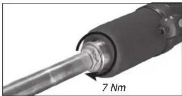
- Depending on the choice of the new inductor: unscrew the adapter with the supplied wrench and then screw the appropriate adapter back on (max. 7 N.m) or keep the adapter already in place.
- Screw the new inductor back on.
- Press the button again (10).
The pump activates. For 5 seconds, the LEDs display a wait pattern.
If the flow is correct, the machine emits a double «BEEP» and the product is ready to operate.
natural_image
Mechanical device with numbered components, no visible text or symbolsOtherwise a fault is displayed (refer to the fault code table).
Inductors et Adaptators
The Powerduction 110LG/160LG/220Lg are delivered as standard with the 32L adapter and the L90 or L20B4 inductor. (depending on model).
The other accessories are optional, they allow to extend the heating possibilities to multiple applications.

| Adaptators | ||||||
| 32LRef. 064515 | 32SRef. 064508 | |||||
| Inductors | ||||||
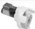
 | L90Ref. 059788 |  | L20/B4Ref. 067882 |  | S90Ref. 058927 |  S70Ref. 061569 S70Ref. 061569 |
 | L70Ref. 059771 |  | L20 ALU GLOVERef. 069114 |  | S180Ref. 059269 |  S20/B1Ref. 064874 S20/B1Ref. 064874 |
 | L180Ref. 059795 |  | L180 D80Ref. 069121 |  | S180/B1Ref. 064881 |  S180/B3 WRef. 067899 S180/B3 WRef. 067899 |
 | L180 SPIRALRef. 065000 | |||||
WEIGHT OF POWERDUCTION LANCES
The weight of the spears was measured with the arm extended. (These measurements are for guidance only and cannot be 100% accurate as they depend on the position of the spear on the scale).
| 37LG 39/50LG 110LG 160/220LG | |||||
| S90 inductor (without liquid) | 1.4 kg 1.5 | kg The excluded beam | |||
| Inductor S90 (with liquid circulation) | 1.6 kg 1.7 | kg The excluded beam | |||
| S180B3 inductor (without liquid) | 1.4 kg The | excluded beam | |||
| Inductor S180B3W (with liquid circulation) | 1.6 kg The | excluded beam | |||
| C20B1 inductor (without liquid) | 1.4 kg The | excluded beam | |||
| Inductor C20B1 (with liquid circulation) | 1.6 kg The | excluded beam | |||
| L90 inductor (without liquid) | 4.8 kg 3.4 kg | Stem diagram (110) + balancer diagram | |||
| 4.6 kg 4.5 kg The excluded beam | |||||
| Inductor L90 (with liquid circulation) | 5.3 kg 3.6 kg | Stem diagram (110) + balancer diagram | |||
| 5 kg 5.1 kg The excluded beam | |||||
| L20B4 inductor (without liquid) | 4.7 kg 2.9 kg | Stem diagram (110) + balancer diagram | |||
| 4.5 kg 4.3 kg The excluded beam | |||||
| Inductor L20B4 (with liquid circulation) | 5.1 kg 3.2 kg | Stem diagram (110) + balancer diagram | |||
| 4.9 kg 4.7 kg The excluded beam | |||||
«PURGE» MODE
This mode is only available if the heat is not activated (green switch is off).
- Push the button (10), the pump stops and the LED (9) lights up.
- Position the torch on its support and place the cable on the floor (to avoid liquid spillage).
- Unscrew the accessory by hand.
- Push and hold the heat authorisation button (2) for 3 seconds until it lights up.
- Place the torch button above a bucket with a capacity of 10 l minimum.
- Push the torch button (11). The pump activates until the debit falls under 2 l/minute or for 2 minutes. The machine displays the debit in decilitre per minute. To interrupt the pump during the cycle, push any button.
- To empty the cooling circuit, use a blower to blow air (30PSI) at the end of the torch until you can hear the air flowing or projections of liquid coming out of the tank.
- To remove the remaining liquid from the bottom of the tank
110 LG: use a vacuum pump or tilt the product to the front.
160LG/220LG: unscrew the cap under the Powerduction with a wrench (6 pan of 8).
Once the tank is completely empty, screw the cap back on.
natural_image
Technical line drawing of a mechanical device with fan, wheels, and control panel (no text or symbols)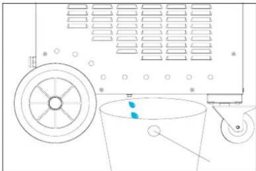
natural_image
Technical line drawing of a mechanical device with pulley, bucket, and wheel (no text or symbols)- To top up the cooling liquid, refer to the installation instructions (p9/10).
It is advisable to change the coolant every year if you are using it intensively, otherwise the Powerduction lance will deteriorate.
COOLING CIRCUIT AND «FORCED COOLING» MODE
The Powerduction is equipped with fans. The first, common to 110LG, 160LG and 220LG, starts when the coolant temperature reaches 35^ C ( 95^ F). The second, only available on the 160LG and 220LG, starts when the temperature reaches 40^ C ( 104^ F). As soon as the liquid temperature drops below the setpoint values ( 35^ C or 40^ C), the fans switch off.
During long periods of use, the POWERDUCTION has a forced cooling mode. To activate it :
- Set the main switch (1) to ON.
The machine initialises in 2 seconds.
-
Press the activation button (2). The indicator on button (2) and the lance support LED (12) both switch on, indicating that the machine is ready to operate.
-
Hold (>3 seconds) the button (10). The « Forced cooling» mode is activated.
The cooling fan then starts automatically. The cooling fan will be audible and the «Fan ON» message will appear on the display.
To stop the «Forced cooling», press the activation button to stop the heating or hold the button (10) again. The message «Fan OFF» is displayed.
IMPLEMENTATION OF OUTDOOR TEMPERATURE CONTROL
- Use a pyrometer or thermocouple sensor with an analog output.
In this case, the value of the shunt resistance must be adjusted to U T° according to the set point and the desired accuracy.
Correspondence table
| Voltage U T° Temperature in Celsius Temperature in fahrenheit | |
| 1 V 0°C 32°F | |
| 2 V 100°C 210°F | |
| 3 V 200°C 390°F | |
| 4 V 300°C 570°F | |
| 4.5 V 350°C 660°F |
Or
- Use the device provided for this purpose on the POWERDUCTION (061644 - POWERDUCTION HEAT CONTROLLER & 064119 - PYROMETER FOR POWERDUCTION HEAT CONTROLLER):
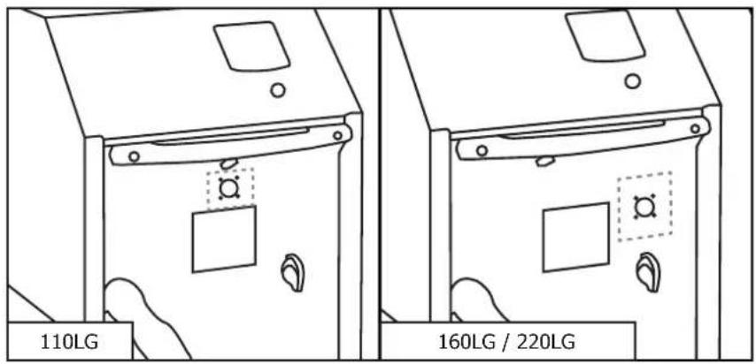
- Connect your temperature sensor to the outdoor temperature measurement interface (Option). In this case, refer to the instructions for the temperature control box.
- Connect the temperature sensor directly to the POWERDUCTION interface or directly to the front panel connector. Pin assignment of the front panel connector
text_image
110LG 160LG / 220LG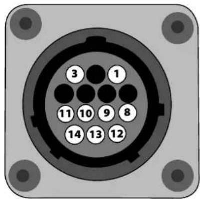
text_image
3 1 11 10 9 8 14 13 12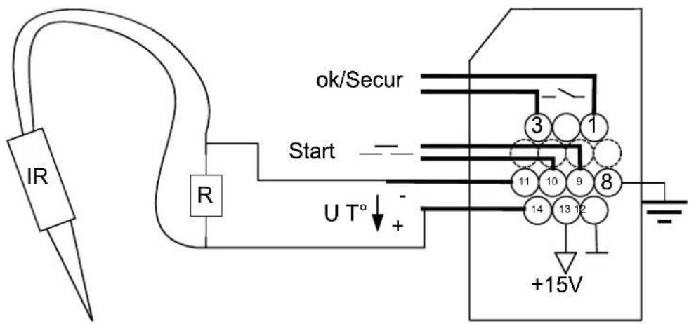
text_image
IR R Start ok/Secur 3 1 11 10 9 8 14 13 12 +15V| Fonction | Wire number | Type Electrical parameters Values | Logics | |
| Generator ready OK/Secur | 1/3 Digital output | Type Permissible direct current | Dry contact 5 A 30 V | Closed Generator ready to heat |
| Open Generator fault | ||||
| Earth 8 Earth Earth Earth | ||||
| Start | 9/10 Digital input | Residual voltage (open circuit)Input impedance | 15 V3.5 kΩ | Requires the use of a dry contact: a closed contact activates the heating. |
| Regulation voltage U T° | 11 - / 14+ | Analog input | Maximum input voltageInput impedanceAccuracy | 5 V5.4 kΩ+/-5%Image input of the measured temperature.See correspondence table |
| Interface power supply | 12/13 | Continuous power supply | Output voltageOutput impedance | 15 V100 Ω |
Manual mode
To enter the "outdoor temperature control" mode:
- Keep the heating enable button (2) pressed for 5 seconds.
- The button flashes every second and "rEG" is displayed.
→ The OK/Secure contact closes (Tab 1-3).

The button on the lance (11) and the pneumatic control (15) on the product are disabled in this mode!
To set and then activate the heating:
- Adjust the regulation set point: press the adjustment buttons (4).
The regulation set point varies from 80°C to 350°C (default value at 250°C) in 10°C steps.
The setpoint is displayed for 1 second.
-
Set the heating power set point (%): hold down the "inductor change" button (10) and press the control buttons (4). The heating power setpoint varies from 10% to 100% (default value is 50%). The power is updated on the bar graph.
-
Activate heating: Close the user contact (Start 9-10). As long as it remains closed, the heating is active.
The minimum power indicator light (3) flashes at 10 Hz to indicate that the power is active.
| It is possible to reset the heater when it is active. In this case, it is not necessary to perform step 3 since the user contact is already closed. The heating in progress adapts to his new instructions. | |
| When using the outdoor temperature interface, disconnect the pneumatic pedal from the product and connect it to the interface. |
PLC mode
It is possible to order the product via a PLC (see pinning).
Use the front panel connector or through the external interface.
To enter the "outdoor temperature control" mode:
- Switch on the product.
- Wait until the end of the start-up phase for 5 s.
- Close the Start contact.
- Wait for the OK/Secure output to close.
- Release the Start contact after detecting the OK/Secure.
- Check that the OK/Secure output remains closed.
The product enters the "external regulation mode" and generates a melody.
The heating enable button (2) and the lance button LED (11) flash once per second as long as the mode is activated.
To set the temperature set point and heating power, perform the same operation as in manual mode.
To activate the heating
- Close the Start contact. The product will heat up until it reaches and regulates the set temperature.
| If the product detects a fault, then the OK/Secure output opens and the heating stops. To acknowledge the fault, open the Start contact and press the heating enable button (2). The product returns to the “regulation” mode. |
Start chronogram by PLC
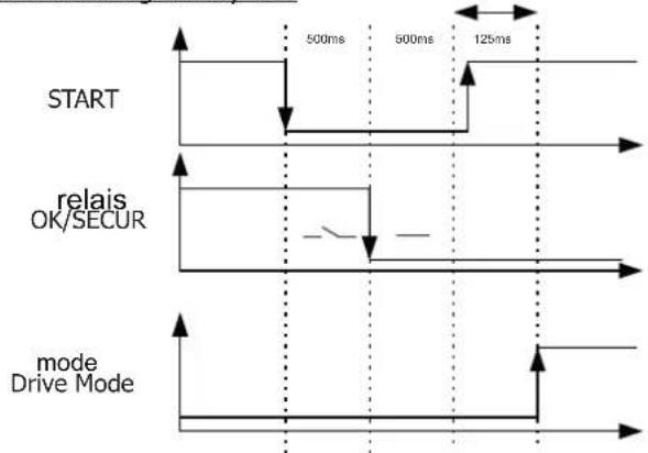
flowchart
graph TD
    A["START"] --> B["relais OK/SECUR"]
    B --> C["mode Drive Mode"]
    style A fill:#f9f,stroke:#333
    style B fill:#ccf,stroke:#333
    style C fill:#cfc,stroke:#333
Safety and fault setting of the device
- If the temperature input does not change after 5 s, the product goes into fault "E12".
- If a thermocouple cuts out, then the regulation stops because the voltage U T° exceeds the maximum voltage of 4.9 V.
- If the temperature drops significantly in a short period of time (when thermocouple probes are disconnected, for example), the heating stops and the product goes into fault "E11" (Manual mode >100°C, PLC mode >30°C).
- To have the most accurate regulation possible, the measuring point(s) must be as close as possible to the inductor. This is the reason for the 2 thermocouples on the external interface.
- The display shows the highest temperature measured by the sensors.
MAINTENANCE
General recommendations
- It is advisable to change the coolant every 2 years at the latest, regardless of use, otherwise the POWERDUCTION lance may deteriorate. Before adding the liquid, dust the product and check for leaks.
- Regularly check the tightening of the power screws and the appearance of the electrical power connections.
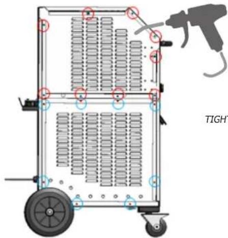
- Open the product every year (unplug it beforehand, and remove the 17 screws on the right-hand side) to remove dust. Or more regularly if the environment is very dusty. (On 160LG & 220LG models only.)
text_image
TIGHTTIGHTENING TORQUE 4 NM FOR SCREWING ON
Recommended tightening torque for power screws
| Dimensions screws M5 | M6 | M8 | M10 clamp | Gas _1/4 3/8 Gas | M28 M32 | Inductor16/22 | ||||
| Material steel steel brass brass copper copper copper | ||||||||||
| Torque | 4 Nm | 6 Nm | 7 Nm | 7 Nm | 2,5 Nm | 4 Nm | 7 Nm max | 7 Nm max | by hand,4 Nm max | |
- It is essential that the maintenance of the product is performed by qualified, authorised staff, that is fully aware of the recommendations outlined in this manual.
- Never clean, lubricate or perform maintenance on the product when it's being used.
- Before any maintenance work, set the On / Off switch to « 0 » to switch off the machine, .then disconnect it it from the mains power supply to prevent any electrical shock or other risks resulting from improper handling.
- Do not wear rings, watches, jewellery, hanging clothes (e.g. ties), torn clothes, scarves, unbuttoned or unzipped jackets, or anything that could get caught during the operation of the machine
natural_image
Close-up of a mechanical component with a 7 Nm radius annotation (no other text or symbols visible)- Rather wear clothing specifically designed for the prevention of accidents, such as: non-slip shoes, anti-noise helmets, protective goggles, safety shoes, etc ...
- Never use petrol or flammable solvents to clean the product. Prefer the use of water and, if necessary, non toxic commercial solvents.
• After maintenance, always put and secure the metal covers back on, before switching the machine on. - The ferrite on inducer can be replaced if damaged.
• Preventive maintenance
Meticulous inspections should be carried out at regular intervals to quickly detect and eliminate faults, so they will not cause damage to the device.

Prior to each use of the POWERDUCTION, check the unit's security systems and any anomalies that may hinder the proper operation of the device. Perform daily checks to identify signs of wear.

The operational safety of the product can only be guaranteed if the repairs are carried out using original spare parts, and if the maintenance instructions are followed.
After each use and once the product is switched off, it should be cleaned immediately to remove any dust or dirt that may impair cooling efficiency, affect the proper functioning of the product and reduce its lifespan. Before each use, check the good operation of the main systems, security systems, and all the electrical cables connection.

Perform periodic visual inspections to verify that there are no cooling liquid leaks, and check that the vents are not obstructed.
ELECTRICAL CONNECTIONS
The product is designed to operate on a single phase power supply from 208 V to 240 V or 340 V to 460 V.
The warranty covers faulty workmanship for 2 years from the date of purchase (parts and labour).
The warranty does not cover:
- Transit damage.
- Normal wear of parts (eg.: cables, clamps, etc...).
- Damages due to misuse (power supply error, dropping of equipment, disassembling).
- Environment related failures (pollution, rust, dust).
- Inductors and removable ferrites that are consumables.
In case of failure, return the unit to your distributor together with:
- The proof of purchase (receipt etc...)
- A description of the fault reported
SICHERHEITSHINWEISE
natural_image
Hand interacting with a device icon, showing green arrow and white body (no text or symbols)natural_image
Close-up of a mechanical component with a metallic shaft and cylindrical housing (no visible text or symbols)Max. Drehmoment = 7 Nm
natural_image
Mechanical assembly diagram showing a rotating component with numbered parts (no text or symbols visible)natural_image
Technical line drawing of a mechanical device with cooling fans and a piping (no text or symbols)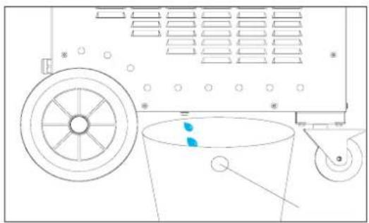
natural_image
Diagram of a mechanical device with a wheel, bucket, and wheel handle (no text or symbols)DREHMOMENT 4 NM ZUM NACHSCHRAUBEN
natural_image
Hand interacting with a device on a black surface, showing directional arrows and a green circle highlighting a point (no text or symbols)MODO "TEMPORIZADOR"
natural_image
Close-up of a black industrial tool with a metallic shaft and cylindrical component (no visible text or symbols)max = par 7N
natural_image
Mechanical device with numbered components and a rotating knob (no visible text or symbols) | L90Ref. 059788 |  | L20/B4Ref. 067882 |  | S90Ref. 058927 |  | S70Ref. 061569 |
 | L70Ref. 059771 |  | L20 ALU GLOVERef. 069114 |  | S180Ref. 059269 |  | S20/B1Ref. 064874 |
 | L180Ref. 059795 | 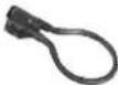 | L180 D80Ref. 069121 | 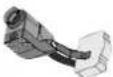 | S180/B1Ref. 064881 | 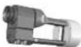 | S180/B3 WRef. 067899 |
PESO DE LAS LANZAS POWERDUCTION
natural_image
Technical diagram of a 110 LG air conditioning unit with fan and control panel (no text or symbols on the device itself)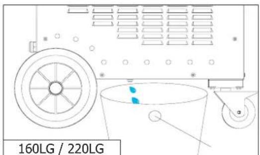
text_image
160LG / 220LGnatural_image
Close-up of a mechanical component with a 7 Nm scale indicator (no text or symbols on the object itself)natural_image
Hand interacting with a device icon, showing a green circle highlighting a button (no text or symbols present)natural_image
Close-up of a mechanical tool with a metallic shaft and black handle (no visible text or symbols)natural_image
Mechanical device with numbered components (2, 3, 4) showing assembly or mounting features (no visible text or symbols)natural_image
Technical line drawing of a 110 LG air duct system with fan and pipe (no text or symbols on the diagram itself)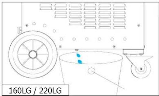
text_image
160LG / 220LGnatural_image
Close-up of a mechanical component with a 7 Nm radius annotation (no other text or symbols visible)BESCHRIJVING VAN HET APPARAAT (FIG I)
natural_image
Hand interacting with a black electronic device, showing a green dot and directional arrows (no text or symbols)TIJDVERTRAGINGSMODUS\*
natural_image
Close-up of a black industrial tool with a metallic shaft and cylindrical component (no visible text or symbols)maximumkoppel = 7N
natural_image
Mechanical device with numbered components (2, 3, 4) showing no visible text or symbolsInductoren & adapters
 32LRef. 064515 32LRef. 064515 |  32SRef. 064508 32SRef. 064508 | ||||
| Inductoren | |||||
 L90Ref. 059788 L90Ref. 059788 | 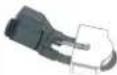 L20/B4Ref. 067882 L20/B4Ref. 067882 |  S90Ref. 058927 S90Ref. 058927 |  S70Ref. 061569 S70Ref. 061569 | ||
 L70Ref. 059771 L70Ref. 059771 |  L20 ALU GLOVERef. 069114 L20 ALU GLOVERef. 069114 |  S180Ref. 059269 S180Ref. 059269 | 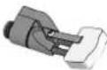 S20/B1Ref. 064874 S20/B1Ref. 064874 | ||
 L180Ref. 059795 L180Ref. 059795 |  L180 D80Ref. 069121 L180 D80Ref. 069121 |  S180/B1Ref. 064881 S180/B1Ref. 064881 |  S180/B3 WRef. 067899 S180/B3 WRef. 067899 | ||
 L180 SPIRALRef. 065000 L180 SPIRALRef. 065000 | |||||
GEWICHT VAN POWERDUCTION LANSEN
natural_image
Technical line drawing of a mechanical device with fan, wheels, and control panel (no text or symbols)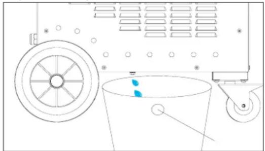
natural_image
Technical line drawing of a mechanical device with wheels, bucket, and wheel (no text or symbols)natural_image
Close-up of a mechanical component with a 7 Nm scale indicator (no text or symbols on the object itself)natural_image
Hand interacting with a device icon, showing directional arrows and a green dot (no text or symbols)"MODALITÀ "TIMER"\*
natural_image
Close-up of a black industrial tool with a metallic shaft and cylindrical component (no visible text or symbols)coppia massima = 7N
natural_image
Mechanical assembly with numbered components (no visible text or symbols)natural_image
Technical diagram of a 110 LG industrial machine with cooling fan and control panel (no text or symbols on the device itself)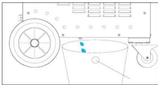
natural_image
Technical line drawing of a mechanical device with a wheel, bucket, and pulley (no text or symbols)natural_image
Close-up of a mechanical component with a 7 Nm scale indicator (no text or symbols on the object itself)text_image
Exploded view diagram of a mechanical assembly with numbered components for identificationtext_image
Technical diagram of a mechanical assembly with numbered components and an inset showing a close-up view of a cylindrical component.Powerduction 110 & 160 LG
text_image
Exploded view diagram of a mechanical assembly with numbered components for identification| N° Désignation | 160LG 220LG208-240 V 400 V | |||
| 1 Pompe / Pump / Pumpe / Bomba / Hacoc / Pomp / Pompa 71960 71745 | ||||
| 2 | Roue pivotante avec frein / Swivel wheel with brake / Schwenkrad mit Bremse / Rueda giratoria con freno / Шарнирное колесо с тормозом / Zwenkwiel met rem / Ruota girevole con freno | 71362 | ||
| 3 Roue / Wheel / Rad / Rueda / Колесо / Wiel / Ruota 71376 | ||||
| 4 | Axe de roue / Wheel axle / Radachse / Eje de la rueda / Ось колеса / Wielas / Asse delle ruote | 90082ST | ||
| 5 | Radiateur à eau / Water radiator / Wasserkühler / Radiador de agua / Водяной радиатор / Waterradiator / Radiatore dell'acqua | 71777 | ||
| 6 | Ventilateur 225x225x80 / Ventilator 225x225x80 / Beatmungsgerät225x225x80 / Ventilador 225x225x80 / Вентилятор 225x225x80 / Ventilator225x225x80 / Ventilatore 225x225x80 | 51004 51003 | ||
| 7 | Presse étoupe / Cable gland / Kabelverschraubung / Glándula de cable / кабельный ввод / Klier / Pressacavo | 71135 71164 | + 71164-1 | |
| 8 | Circuit primaire / Primary circuit / Primärer Kreislauf / Circuito primario / Первичный схема / Primair circuit / Circuito primario | E0152C 64674 | + 97461C E0152C | |
| 9 | Condensateur de résonnance / Resonance capacitor / Resonanzkondensator / Condensador de resonancia / Резонансный конденсатор / Resonantiecondensator / Condensatore di risonanza | 52251 52252 | ||
POWERDUCTION 110LG / 160LG / 220LG
| 10 | Transformateur / Transformer / Transformator / Transformador / Трансформатор / Transformator / Trasformatore | 96172 96137 | 96177 | ||
| 11 | Circuit CEM Powerduction / Powerduction EMC circuit / Leistungs-fluss-EMV-Schaltung / Circuito de conducción de energía EMC / Электромагнитная цепь электромагнитной совместимости / Elektriciteitsnet EMC-circuit / Circuito EMC a conduzione di potenza | 97472C | |||
| 12 | Ventilateur 120x120x38 / Ventilator 120x120x38 / Beatmungsgerät 120x120x38 / Ventilador 120x120x38 / Вентилятор 120x120x38 / Ventilator 120x120x38 / Ventilatore 120x120x38 | 51021 | |||
| 13 | Circuit alimentation / Power supply / Stromversorgung / Fuente de alimentación / Источник питания / Stroomvoorziening / Alimentazione | E0023C | E0023Csi fab ≥ 11/2021S81128*si fab < 11/2021 | E0023C | |
| 14 | Circuit CEM / EMC circuit / Leistungsfluss-EMV-Schaltung / Circuito de conducción de energía EMC / Электромагнитная цепь электромагнитной совместимости / Elektriciteitsnet EMC-circuit / Circuito EMC a conduzione di potenza | 97277C | |||
| 15 | Carte entrée puissance / Power input card / Leistungsaufnahme-Karte / Tarjeta de entrada de energía / Карта ввода мощности / Krachtinputkaart / Scheda di ingresso di potenza | E0028C | E0026Csi fab ≥ 11/2021S81128*si fab < 11/2021 | E0028C | |
| 16 | Interrupteur Marche/Arrêt / On/Off switch / Ein/Aus-Schalter / Interruptor de encendido y apagado / Переключатель Вкл/Выкл / Aan/uit-schakelaar / Interruttore On/Off | 52356 + 52360 51061 | |||
| 17 | Interrupteur pneumatique / pneumatic switch / pneumatischer Schalter / interruptor neumático / пневматический выключатель / pneumatische schakelaar / interruttore pneumatico | 71179 | |||
| 18 | Bouton lumineux vert / Green illuminated button / Grün beleuchtete Taste / Botón verde iluminado / Зеленая кнопка с подсветкой / Groen verlichte knop / Pulsante verde illuminato | 51403 | |||
| 19 Clavier / Keyboard / Tastatur / Teclado / Клавиатура / Toetsenbord / Tastiera 51967 | IND X | ||||
| 20 | Poignée plastique / Plastic handle / Kunststoffgriff / Mango de plástico / Пластиковая ручка / Kunststof handvat / Maniglia in plastica | 56014 | |||
| 21 | Capteur de débit / Flow sensor / Durchflusssensor / Sensor de flujo / Датчик расхода / Stromingssensor / Sensore di flusso | 81103 | |||
| 22 | Mat potence / Mat gallows / Matten-Galgen / La horca de esteras / Флагшток виселица / Matgalg / Forca di stuoia | 91148GF | |||
| 23 Rail potence 91129GT | |||||
| 24 Support faisceau potence 99942GT | |||||
| 25 | Carte de commande / Control card / Kontrollkarte / Tarjeta de control / Карта управления / Besturingskaart / Scheda di controllo | Si fab < 20.11 : S97788Si fab = 20.11 : Consulter SAVSi fab > 20.11 : 97788C | |||
| 26 | Cordon secteur / Power cord / Netzkabel / Cable de alimentación / шнур питания / Stroomkabel / Cavo di alimentazione | A0104 21470 | |||
| 27 | Lance / Induktorkabel / a lance / Lanza / горелка индуктора / de lans / Lancia | SA0091 | S93820 | SA0091(6 m) | SA0190(10 m) |
| 28 | Kit de remplacement boitier de raccordement Powerduction / Powerduction connection box replacement kit / Ersatzkit für die Anschlussbox von Powerduction | S81115 | |||
| 29 | Circuit adaptation interface clavier / Keyboard interface adaptation circuit / Schaltung zur Anpassung der Tastaturschnittstelle / Circuito de adaptación de la interfaz del teclado / Схема настройки интерфейса клавиатуры / Toetsen-bordinterface aanpassingscircuit / Circuito di adattamento dell'interfaccia della tastiera | 97782C | |||
| 30 Self / Self / Selbst / Self / Self / Zelf / 96173 96148 96173 | |||||
| 31 | Nappe / Ribbon cable / Flachbandkabel / Cable plano / ленточный кабель / Lint kabel / Cavo a nastro | 63781 | |||
*S81128 : Inclus le circuit d'alimentation et la carte entrée puissance / Includes power supply circuit and power input board / Inklusive Stromkreis und Leistungseingangskarte / Incluye circuito de alimentación y placa de entrada de energía / Vключает схему питания и плату ввода питания / Inclusief stroomtoevoercircuit en stroominvoerbord / Include il circuito di alimentazione e la scheda di ingresso dell'alimentazione.
text_image
Technical diagram of a mechanical device with numbered parts and exploded view, showing assembly steps from component 1 to final assembly.Powerduction 220LG
text_image
Technical diagram of mechanical assembly with numbered parts for identification| N° Désignation Ref | ||
| 1 | Collier de serrage / Hose clamp / Schlauchschelle / Abrazadera para tubo / Хомут / Klem / Morsetto | 56228 |
| 2 | Poignée axiale / Axial handle / Axialer Griff / Asa axial / Осевая ручка / Axiaal handvat / Maniglia assiale | 56276 |
| 3 | Kit poignée / Handle kit / Handgriff-Satz / Kit de asas / набор рукояток / Greep kit / Kit maniglia | SA0101 |
| 4 | Kit Molette / Knob Kit / Knopf-Kit / Kit de rueda / комплект колес / wielset / kit di ruote | SA0100 |
| 5 | Écrou M10 / nut M10 / Mutter M10 / Tuerca M10 / Гайка M10 / Moer M10 / Dado M10 | 41159 |
| 6 | Support Pince Fixation generateur / Support Clamp Generator mounting / Halteklammer Generatormontage / Abrazadera de soporte Montaje del generador / Опорный зажим Монтаж Генератор / Steun Klem Generator montage / Morsetto di supporto Montaggio del generatore | 56162 |