PA5240 - Receiver Monacor - Free user manual and instructions
Find the device manual for free PA5240 Monacor in PDF.
| Product Type | 5-zone Public Address amplifier-mixer |
| Brand | Monacor |
| Model | PA5240 |
| Total RMS power 100 V outputs | 240 W RMS (5 × 100 W max, total must not exceed 240 W) |
| RMS power 8 Ω output | 1 × 240 W RMS |
| Maximum output power | 340 W |
| Number of zones | 5 zones (individual attenuators) |
| Microphone inputs | 4 inputs (Mic 1-4), sensitivity 2.5 mV, balanced |
| Line inputs | 6 inputs: Line 2-4 (250 mV), Aux 5-7 (250 mV) |
| Speaker outputs | 5 × 100 V (zones), 1 × 100 V direct, 1 × 8 Ω direct |
| Distortion rate | < 1% |
| Frequency response | 55 – 16000 Hz |
| Signal/noise ratio (Line) | > 80 dB (A-weighted) |
| Signal/noise ratio (Mic) | > 70 dB (A-weighted) |
| Tone controls | Bass ±10 dB at 100 Hz, Treble ±10 dB at 10 kHz |
| Mains power supply | 230 V / 50 Hz, 750 VA |
| Emergency power supply | 24 V (--), max consumption 20 A |
| Dimensions (W × H × D) | 482 × 133 × 352 mm, 3U rack |
| Weight | 16 kg |
| Operating temperature | 0 – 40 °C |
| Maintenance and cleaning | Use a dry, soft cloth, no chemicals or water |
| Included accessories | Mains cord, terminal protection cover |
| Spare parts and repairability | Repair by qualified technician; replaceable fuse of same type |
Frequently Asked Questions - PA5240 Monacor
User questions about PA5240 Monacor
0 question about this device. Answer the ones you know or ask your own.
Ask a new question about this device
Download the instructions for your Receiver in PDF format for free! Find your manual PA5240 - Monacor and take your electronic device back in hand. On this page are published all the documents necessary for the use of your device. PA5240 by Monacor.
USER MANUAL PA5240 Monacor
PA Mixing Amplifier for 5 Zones
Please read these operating instructions carefully prior to operation and keep them for later reference. All operating elements and connections described can be found on the fold-out page 3.
Connection of the speakers (chapter 5) requires adequate technical knowledge in 100 V PA technology and is to be made by experts only. Operation of the amplifier is easy (chapter 6), even for adults without any expert knowledge. However, in case of any queries, please contact your installer or retailer.
1 Operating Elements and Connections
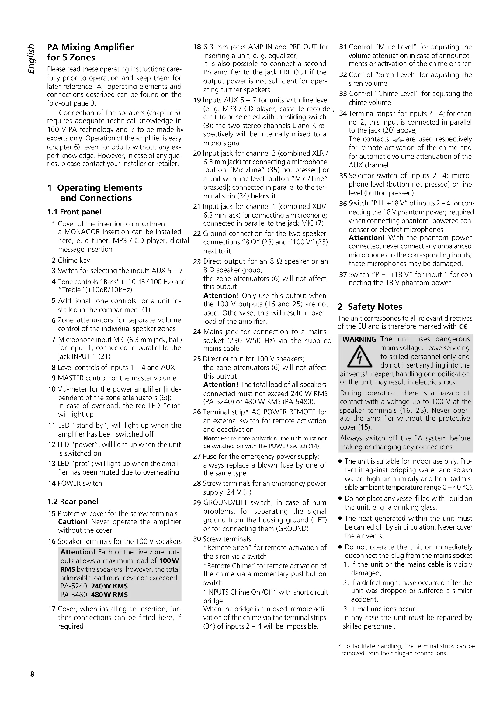
1.1 Front panel
1 Cover of the insertion compartment; a MONACOR insertion can be installed here, e. g tuner, MP3 / CD player, digital message insertion
2 Chime key
3 Switch for selecting the inputs AUX 5 - 7
4 Tone controls "Bass" (±10 dB / 100 Hz) and "Treble" (±10dB/10kHz)
5 Additional tone controls for a unit installed in the compartment (1)
6 Zone attenuators for separate volume control of the individual speaker zones
7 Microphone input MIC (6.3 mm jack, bal.) for input 1, connected in parallel to the jack INPUT-1 (21)
8 Level controls of inputs 1 – 4 and AUX
9 MASTER control for the master volume
10 VU-meter for the power amplifier [independent of the zone attenuators (6)]; in case of overload, the red LED "clip" will light up
11 LED "stand by", will light up when the amplifier has been switched off
12 LED "power", will light up when the unit is switched on
13 LED "prot"; will light up when the amplifier has been muted due to overheating
14 POWER switch
1.2 Rear panel
15 Protective cover for the screw terminals Caution! Never operate the amplifier without the cover.
16 Speaker terminals for the 100 V speakers
Attention! Each of the five zone outputs allows a maximum load of 100W RMS by the speakers; however, the total admissible load must never be exceeded: PA-5240 240W RMS PA-5480 480W RMS
17 Cover; when installing an insertion, further connections can be fitted here, if required
18 6.3 mm jacks AMP IN and PRE OUT for inserting a unit, e. g. equalizer; it is also possible to connect a second PA amplifier to the jack PRE OUT if the output power is not sufficient for operating further speakers
19 Inputs AUX 5 – 7 for units with line level (e. g. MP3 / CD player, cassette recorder, etc.), to be selected with the sliding switch (3); the two stereo channels L and R respectively will be internally mixed to a mono signal
20 Input jack for channel 2 (combined XLR / 6.3 mm jack) for connecting a microphone [button "Mic /Line" (35) not pressed] or a unit with line level [button "Mic / Line" pressed]; connected in parallel to the terminal strip (34) below it
21 Input jack for channel 1 (combined XLR/6.3 mm jack) for connecting a microphone; connected in parallel to the jack MIC (7)
22 Ground connection for the two speaker connections "8 Ω" (23) and "100 V" (25) next to it
23 Direct output for an 8 Ω speaker or an 8 Ω speaker group; the zone attenuators (6) will not affect this output
Attention! Only use this output when the 100 V outputs (16 and 25) are not used. Otherwise, this will result in overload of the amplifier.
24 Mains jack for connection to a mains socket (230 V/50 Hz) via the supplied mains cable
25 Direct output for 100 V speakers; the zone attenuators (6) will not affect this output
Attention! The total load of all speakers connected must not exceed 240 W RMS (PA-5240) or 480 W RMS (PA-5480).
26 Terminal strip* AC POWER REMOTE for an external switch for remote activation and deactivation
Note: For remote activation, the unit must not be switched on with the POWER switch (14).
27 Fuse for the emergency power supply; always replace a blown fuse by one of the same type
28 Screw terminals for an emergency power supply: 24 V (=)
29 GROUND/LIFT switch; in case of hum problems, for separating the signal ground from the housing ground (LIFT) or for connecting them (GROUND)
30 Screw terminals
"Remote Siren" for remote activation of the siren via a switch
"Remote Chime" for remote activation of the chime via a momentary pushbutton switch
"INPUTS Chime On /Off" with short circuit bridge
When the bridge is removed, remote activation of the chime via the terminal strips (34) of inputs 2 - 4 will be impossible.
31 Control "Mute Level" for adjusting the volume attenuation in case of announcements or activation of the chime or siren
32 Control "Siren Level" for adjusting the siren volume
33 Control "Chime Level" for adjusting the chime volume
34 Terminal strips* for inputs 2 - 4; for channel 2, this input is connected in parallel to the jack (20) above;
The contacts are used respectively for remote activation of the chime and for automatic volume attenuation of the AUX channel.
35 Selector switch of inputs 2–4: microphone level (button not pressed) or line level (button pressed)
36 Switch "P.H. +18 V" of inputs 2–4 for connecting the 18 V phantom power; required when connecting phantom-powered condenser or electret microphones
Attention! With the phantom power connected, never connect any unbalanced microphones to the corresponding inputs; these microphones may be damaged.
37 Switch "P.H. +18 V" for input 1 for connecting the 18 V phantom power
2 Safety Notes
The unit corresponds to all relevant directives of the EU and is therefore marked with €€
WARNING
The unit uses dangerous mains voltage. Leave servicing to skilled personnel only and do not insert anything into the
air vents! Inexpert handling or modification of the unit may result in electric shock.
During operation, there is a hazard of contact with a voltage up to 100 V at the speaker terminals (16, 25). Never operate the amplifier without the protective cover (15).
Always switch off the PA system before making or changing any connections.
- The unit is suitable for indoor use only. Protect it against dripping water and splash water, high air humidity and heat (admissible ambient temperature range 0 – 40 °C).
- Do not place any vessel filled with liquid on the unit, e. g. a drinking glass.
- The heat generated within the unit must be carried off by air circulation. Never cover the air vents.
-
Do not operate the unit or immediately disconnect the plug from the mains socket
-
if the unit or the mains cable is visibly damaged,
-
if a defect might have occurred after the unit was dropped or suffered a similar accident,
-
if malfunctions occur.
In any case the unit must be repaired by skilled personnel.
- Never pull the mains cable when disconnecting the mains plug from the socket, always seize the plug.
- For cleaning only use a dry, soft cloth; never use chemicals or water.
- No guarantee claims for the unit or liability for any resulting personal damage or material damage will be accepted if the unit is used for other purposes than originally intended, if it is not correctly connected or operated, or if it is not repaired in an expert way.

If the unit is to be put out of operation definitively, take it to a local recycling plant for a disposal which is not harmful to the environment.
3 Applications and Accessories
The amplifiers PA-5240 and PA-5480 have been specially designed for use in 100 V PA systems. 100 V outputs for up to five speaker zones are available. The volume of these zones can be individually adjusted. To the five input channels which can be mixed with one another, microphones (channels 1 – 4) or units with line level (channels 2 – 5) can be connected. One of the following MONACOR insertions can be installed into the insertion compartment (1):
| PA-1120DMT | digital message storage with timer |
| PA-1140RCD rad | o/CD player |
| PA-1200C timer | |
| PA-1200RDS AM | FMradio |
The MONACOR PA PTT desk microphone PA-5000PTT has been specially designed as a separate accessory for these amplifiers and can be connected to the terminal strips (34) of channels 2–4.
4 Setting up the Amplifier
The amplifier has been designed for installation into a rack (482 mm / 19"), however, it can also be used as a table top unit. In any case, air must be allowed to pass through all air vents to ensure sufficient cooling of the power amplifier.
4.1 Installation into a Rack
For installation into a rack, 3 rack spaces (133 mm) are required. To prevent top-heaviness of the rack, the amplifier must be inserted into the lower part of the rack. The front panel alone will not be able to secure the unit; side rails or a base plate must be additionally provided.
The hot air blown out at the side of the amplifier must be dissipated from the rack; otherwise, heat will accumulate in the rack which may not only damage the amplifier but also other units in the rack. In case of insufficient heat dissipation, install a ventilation unit into the rack.
5 Connecting the Amplifier
All connections should only be made by qualified skilled personnel. For this purpose, always switch off the amplifier!
Numerous connections, e. g. those for the speakers, are underneath the protective cover (15). For connection, unscrew the cover.
WARNING
Do not operate the amplifier without the protective cover (15). During operation, there is a hazard of contact
with a voltage up to 100 V at the speaker terminals (16, 25). After connecting, screw on the cover again so that the terminals are protected against any accidental contact.
5.1 Speakers
1) Either connect 100 V speakers for the five speaker zones to the terminals ATT ZONE OUTPUTS (16)
Attention! In each speaker zone, the maximum load by the 100 V speakers may be 100 W RMS; however, the total admissible load of all speakers must not be exceeded:
240W RMS (PA-5240) or
480W RMS (PA-5480)
2) or a speaker group of a total impedance of at least 8 Ω to the terminals COM (22) and 8 Ω (23). The zone attenuators (6) will not affect this output.
3) Always observe the correct polarity when connecting. For the 8 Ω connection, the terminal COM is the negative pole and the terminal 8 Ω the positive pole. The positive connection of the speaker cables is always specially marked.
4) Additional 100 V speakers, the volume of which is not to be attenuated by the zone attenuators (6) can be connected to the terminals COM (22) and 100 V (25). However, the total load of these speakers and the speakers at the terminals ATT ZONE OUTPUTS must not be exceeded (see note "Attention" above).
5.2 Microphones
Four microphones can be connected, one microphone each to the channels 1 – 4:
- In channel 1 to the jack MIC (7) on the front panel or to the combined XLR / 6.3 mm jack INPUT-1 (21)
A signal in channel 1 will take priority over all other signals, i. e. the volume of the other signals will be automatically attenuated if you speak into the microphone of channel 1.
-
In channel 2 to the combined XLR / 6.3 mm jack INPUT-2 (20) or to the terminal strip (34) below it*
-
In channel 3 to the terminal strip INPUT-3 (34)*
-
In channel 4 to the terminal strip INPUT-4 (34)*
*Note: When the talk button of the microphone PA-5000PTT is pressed, the volume of the AUX channel will be automatically attenuated.
To facilitate handling, it is possible to remove the terminal strips (34) from their plug-in connections on the unit and to reinsert them after connection.
1) Connect the microphones to the corresponding terminals.
Connect the microphones PA-5000PTT to the terminal strips (34) so that it will be possible to activate the chime from these microphones and to attenuate the volume of the AUX channel.
2) In channels 2 - 4, the button "Mic/Line" (35) must not be pressed when connecting a microphone so that the input is switched to microphone sensitivity.
3) When using a phantom-powered microphone, press the corresponding button "P.H. +18V" (36, 37). The microphone will then be supplied with 18 V by the amplifier.
Attention! With the phantom power connected, unbalanced microphones must not be connected to the corresponding inputs; these microphones may be damaged.
5.3 Units with line output
Six units with line output (e.g. MP3/CD player, tuner, tape deck) can be connected, one unit each to channels 2–4 and three units to the AUX channel.
1) Connect the units to the corresponding terminals:
– combined XLR / 6.3 mm jack INPUT-2 (20)
- terminal strips INPUT-2 to INPUT-4 (34)
- RCA jacks AUX INPUTS (19)
When connecting a stereo unit to the combined XLR / 6.3 mm jack (20), use a stereo mono adapter (e. g. SMC-1 from MONACOR) and an adapter cable (e. g. MCA-300 from MONACOR); otherwise, the signals of the stereo centre will cancel out each.
2) In channels 2 – 4, press the corresponding button "Mic / Line" (35) when connecting a unit with line level so that the input is set to line level. To ensure that the phantom power is deactivated, the corresponding button "P.H. +18V" (36) must not be pressed.
3) For the AUX channel, use the selector switch "5 6 7" (3) to select the unit to be heard.
5.4 Inserting an equalizer or another unit
For external effects on the sound, e. g. an equalizer can be inserted via the jacks INSERTS (18).
1) Connect the input of the unit to the jack PRE OUT.
2) Connect the output of the unit to the jack AMP IN.
Note: The signal in the amplifier will be interrupted if merely the jack AMP IN has been connected, if the inserted unit has not been switched on, or if it is defective or not correctly connected. In this case, the speakers connected will remain mute.
5.5 Additional amplifier
If the number of the required speakers is higher than the number admissible for the amplifier, an additional amplifier will be required. Connect the input of the additional amplifier to the jack PRE OUT in the area INSERTS (18). The signal for the additional amplifier will not be affected by the zone attenuators (6).
5.6 Switches for chime and siren
For remote activation of the chime, connect a momentary pushbutton switch to the contacts "Remote Chime" (30). For using the siren, connect a switch to the contacts "Remote Siren" (30). To allow activation from several places, it is possible to connect several switches or momentary pushbutton switches in parallel.
5.7 Switch for remote activation / deactivation
A separate switch allows remote activation and deactivation of the amplifier. For this purpose, connect an on-off switch to the terminal strip AC POWER REMOTE (26). For remote activation or deactivation, the amplifier must not be switched on with the POWER switch (14).
5.8 Power supply and emergency power supply
1) For continued operation of the amplifier after a possible power failure, connect a 24 V emergency power supply unit (e.g. MONACOR PA-24ESP) to the terminals DC POWER 24V= (28). For a cable length of up to 4 m, a cable cross section of 5 mm is required.
Note: If the 24 V voltage from the emergency power supply unit is present at the terminals DC POWER 24V=, the amplifier cannot be switched off with the switch POWER (14). In case of a mains failure or if it is switched off, it switches automatically to the emergency power supply.
2) Finally, connect the mains cable provided to the mains jack (24) and then to a mains socket (230V/50Hz).
3) Even when it is switched off, the amplifier will still consume some power. Therefore disconnect the plug from the mains socket and, if required, disconnect the emergency power supply unit if the amplifier is not used for a longer period.
6 Operation
When the amplifier is switched off and connected to the supply voltage, the LED "stand by" (11) will light up.
1) Prior to switching on the amplifier for the first time, set all five input controls INPUT-1 to INPUT-4, AUX (8) and the MASTER control (9) to zero.
2) Switch on the amplifier with the POWER switch (14) or with a switch connected to the terminal strip AC POWER REMOTE (26). The LED "stand by" will be extinguished, and the LED "power" (12) will light up.
6.1 Adjusting the volume
1) For the time being, set the control INPUT (8) of the signal to be heard at the highest volume to position 7 (e.g. INPUT-1 for emergency announcements in channel 1 of top priority).
2) Set the attenuator ZONE ATTENUATORS (6) of the zone to be provided with the sound of the highest volume to position 5.
3) Make an announcement via the corresponding microphone and adjust the maximum desired volume with the MASTER control (9). However, the LED "clip" of the VU-meter (10) must not light up; otherwise, this will result in overload and distortion of the amplifier. In this case, turn back the MASTER control accordingly.
If the desired volume is not reached and the LED "clip" does not yet light up, advance the corresponding control INPUT further.
4) Then, while an announcement is made, also adjust the volume of the other zones with the attenuators (6).
5) Adjust the volume of further microphones and signal sources with the corresponding controls (8). Always set the controls of the unconnected channels to zero.
6) For selecting a unit connected to the jacks AUX INPUTS (19), actuate the selector switch "5 6 7" (3). For this purpose, first set the control AUX to zero to prevent switching noise.
7) Adjust the sound with the two controls "Bass" and "Treble" (4). Adjust the sound for an insertion in the compartment (1) with the controls PACK (5).
8) For temporary sound interruption in certain zones, set the corresponding attenuators (6) to "off".
6.2 Automatic volume attenuation
- A signal in channel 1 will take priority over all other signals, i. e. the volume of the other signals will be automatically attenuated if you speak into the microphone of channel 1.
- When the talk button of the microphones PA-5000PTT is pressed, the volume of the AUX channel will be automatically attenuated.
- The input signals will also be attenuated if the siren or the chime is activated.
The volume attenuation level can be adjusted from -25 dB to -35 dB with the control "Mute Level" (31).
6.3 Chime
The chime can e. g. be activated prior to an announcement with the key CHIME (2), with a momentary pushbutton switch connected to the terminals "Remote Chime" (30), and with the talk button of a PA PTT microphone. Adjust the chime volume by means of a screwdriver at the control "Chime Level" (33).
To prevent activation of the chime from the PTT microphones connected to the inputs 2 – 4 (34), remove the jumper from the screw terminals "INPUTS Chime On / Off" (30).
6.3.1 Switching over between 2-tone chime and 4-tone chime
A jumper in the amplifier allows selection of 2-tone chime or 4-tone chime.
WARNING The chime must be switched over by skilled personnel only. For this purpose, the amplifier must be opened. Always dis-
connect the mains plug from the socket before opening the amplifier; otherwise, you will risk an electric shock!
1) If an emergency power supply unit is connected, disconnect it from the terminals DC POWER (28) to make sure that the amplifier is definitely out of operation.
2) Unscrew the housing cover of the amplifier.
3) Use the jumper MS 1 on the left PC board at the rear side of the amplifier to make the adjustment:
position "2T" = 2-tone chime
position "4TONE" = 4-tone chime
4) Screw on the housing cover again.
6.4 Alarm siren
The siren can be activated via a switch connected to the terminals "Remote Siren" (30). Adjust the volume by means of a screwdriver at the control "Siren Level" (32).
6.5 GROUND/LIFTswitch
If there is a ground loop when all units have been installed (e. g. from the housing of the amplifier via a rack to another housing of a unit), humming will occur (audible in particular during music passages of low volume). This ground loop can be interrupted with the GROUND/ LIFT switch (29) on the rear panel of the unit. For this purpose, set the switch to LIFT. Humming should stop after that.
On the other hand, the amplifier is not shielded from electric noise fields if the housing is not grounded. In this case, set the switch to GROUND. In case of doubt, set the switch alternately to find the optimum position.
7 Protective Circuit
The amplifier is provided with a protective circuit against overload, overheating and short circuit at the speaker outputs. The power amplifier is ventilated by a fan, the speed of which depends on the temperature of the power amplifier. If the temperature rise is too high despite the ventilation, the amplifier will be muted and the red LED "prot" (13) will light up. In this case, turn the MASTER control (9) to zero, wait until the LED "prot" is extinguished, then switch off the amplifier. Eliminate the fault, e.g.:
- In case of overload, reduce the number of speakers connected or, if possible, adjust a lower power consumption on the speakers. Use a second amplifier, if required (see chapter 5.5).
- In case of overheating, provide an improved air circulation.
- In case of a short circuit at a speaker output, locate the short circuit and eliminate it.
| Specifications PA-5240 PA-5480 | ||
| RMS output power100V outputs*8Ω output*Maximum output power | 5 × 100 W; however, total load must not exceed 240 W1 × 240 W340W | 5 × 100 W; however, total load must not exceed 480 W1 × 480 W680W |
| THD < 1 % | ||
| InputsMic 1–4Line 2–4Aux 5–7Amp InExtension insertion | 2.5 mV, 2 kΩ, balanced250 mV, 200 kΩ, balanced250 mV, 5 kΩ, unbalanced775 mV, 10 kΩ, unbalanced250 mV, 10 kΩ, unbalanced | |
| OutputsSpeakers*ZonesDirect outputsPre Out | 5 × 100 V1 × 100 V, 1 × 8 Ω775 mV/100Ω, unbalanced | |
| Frequency range 55–16 000 Hz | ||
| S/N ratioLineMic | >80 dB (A weighted)>70 dB (A weighted) | |
| Tone controlBassTreble | ±10 dB at 100 Hz±10 dB at 10 kHz | |
| Ambient temperature | 0–40°C | |
| Power supplyMains voltagePower consumptionEmergency power supplyDC consumption | 230 V/50 Hz750 VA24 V (=)20 A max. | 230 V/50 Hz1500 VA24 V (=)40 A max. |
| Dimensions (W × H × D) | 482 × 133 × 352 mm, 3 RS | 482 × 133 × 352 mm, 3 RS |
| Weight 16kg | 17 kg | |
| *Either use the 100 V outputs or the 8 Ω output! | ||
Block diagram see page 29