WS 9140 - Temperature Controller TECHNOLINE - Free user manual and instructions
Find the device manual for free WS 9140 TECHNOLINE in PDF.
| Product type | Temperature station with wireless outdoor transmitter |
| Brand | TECHNOLINE |
| Model | WS 9140 |
| Display | LCD with clock, indoor temperature, outdoor temperature sections |
| Clock | Radio-controlled DCF-77 (manual setting possible) |
| Time format | 24H |
| Alarm | With snooze function (10 min), 85-second ring |
| Indoor temperature | Range -9.9°C to +37.8°C, resolution 0.1°C, reading every 16 seconds |
| Outdoor temperature | Range -39.9°C to +59.9°C, resolution 0.1°C, reception every 4 seconds |
| MIN/MAX memory | Recording and resetting of indoor and outdoor min and max temperatures |
| Transmission | Wireless 868 MHz, range approx. 100 m in open field |
| Station power supply | 2 AA batteries (IEC LR6, 1.5 V) |
| Transmitter power supply | 2 AA batteries (IEC LR6, 1.5 V) |
| Battery life | Approximately 24 months (alkaline batteries recommended) |
| Station dimensions | 73.4 x 25.2 x 158 mm |
| Transmitter dimensions | 38.2 x 21.2 x 128.3 mm |
| Weight | Not specified |
| Mounting | Station: wall or table (foldable stand). Transmitter: wall or flat surface (bracket included) |
| Care and cleaning | Clean with a soft damp cloth. Do not use abrasive products. Do not immerse. |
| Safety | Do not open, do not expose to extreme temperatures, keep out of reach of children, do not use for medical purposes. |
| Repairability | Do not attempt to repair yourself. Return to point of purchase for repair by a qualified technician. |
Frequently Asked Questions - WS 9140 TECHNOLINE
User questions about WS 9140 TECHNOLINE
0 question about this device. Answer the ones you know or ask your own.
Ask a new question about this device
Download the instructions for your Temperature Controller in PDF format for free! Find your manual WS 9140 - TECHNOLINE and take your electronic device back in hand. On this page are published all the documents necessary for the use of your device. WS 9140 by TECHNOLINE.
USER MANUAL WS 9140 TECHNOLINE
natural_image
Two vertical scientific apparatus diagrams: a vertical cylinder with a handle and a horizontal cylinder with horizontal stripes (no text or symbols)natural_image
Technical line drawing of a vertical cylindrical device with internal components and a separate rectangular block on the right (no text or symbols)natural_image
Diagram of a battery with internal compartments and an external battery (no text or symbols)natural_image
Diagram showing a vertical structure with an arrow pointing to a shaded region (no text or symbols)natural_image
Two vertical structural diagrams showing different platform designs (no text or symbols)natural_image
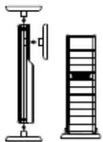
Pure mechanical diagram showing a lever and shaft assembly without any text, numbers, or symbolsCongratulations on purchasing this temperature station with wireless 868 MHz transmission of outdoor temperature and display of indoor temperature. It is further featuring a DCF-77 radio controlled clock and alarm function. With four easy to use function keys, this innovative product is ideal for use in the home or office.

text_image
iT+ 868MHz INSTANT TRANSMISSION®FEATURES:
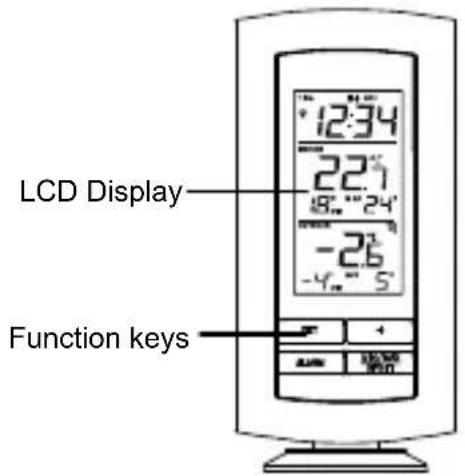
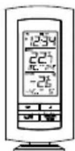
The Temperature Station
text_image
LCD Display Function keys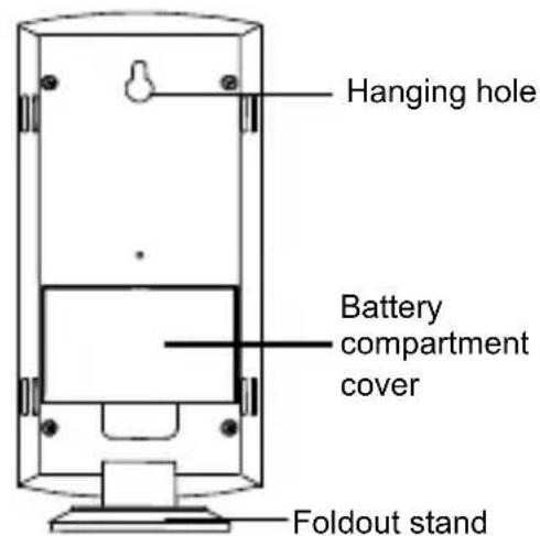
text_image
Hanging hole Battery compartment cover Foldout stand- DCF-77 Radio controlled time function with manual time setting options
- DCF time reception ON/OFF
- 24 hour display
- Alarm function with snooze
• Temperature display in degree Celsius (°C) - Indoor and outdoor temperature with MIN/MAX records
- Manual reset of MIN/MAX records
• Wireless transmission at 868 MHz
• Signal reception intervals at 4 seconds - Low battery indicator
• Wall mounting or table standing (foldout stand)
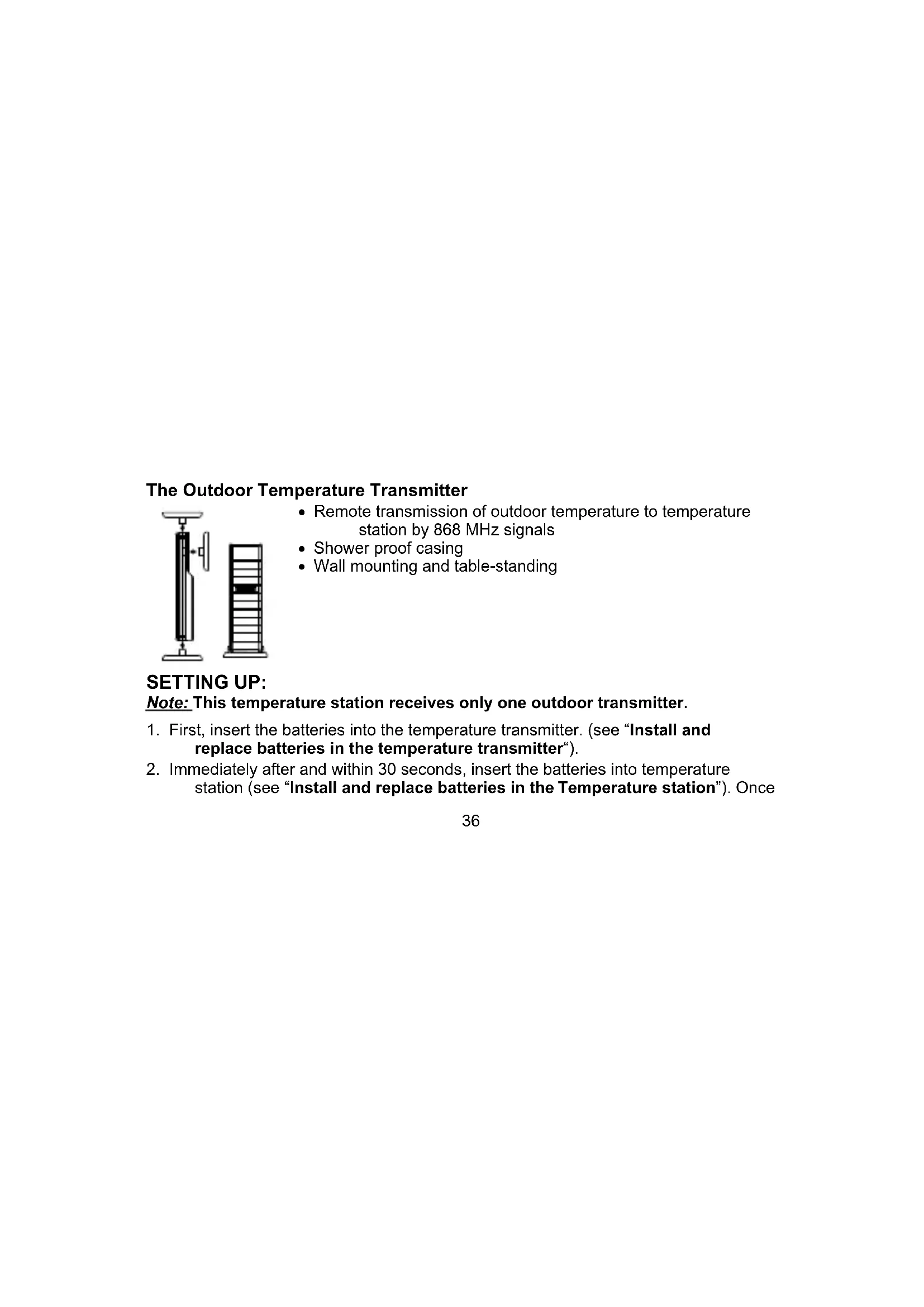
The Outdoor Temperature Transmitter
natural_image
Two mechanical devices: a vertical spring scale and a horizontal cylinder with a handle, shown side by side (no text or symbols visible)- Remote transmission of outdoor temperature to temperature station by 868 MHz signals
- Shower proof casing
• Wall mounting and table-standing
SETTING UP:
Note: This temperature station receives only one outdoor transmitter.
- First, insert the batteries into the temperature transmitter. (see "Install and replace batteries in the temperature transmitter").
- Immediately after and within 30 seconds, insert the batteries into temperature station (see "Install and replace batteries in the Temperature station"). Once
the batteries are in place, all segments of the LCD will light up briefly. Following the time as 0:00 and the weather icon will be displayed. If these are not displayed after 60 seconds, remove the batteries and wait for at least 30 seconds before reinserting them.
-
After inserting the batteries, the temperature station will start receiving data from the transmitter. The outdoor temperature and the signal reception icon should then be displayed on the temperature station. If this does not happen after 3 minutes, the batteries will need to be removed from both units and reset from step 1.
-
In order to ensure sufficient 868 MHz transmission however, this should under good conditions be a distance no more than 100 meters between the final position of the temperature station and the transmitter (see notes on "Mounting" and "868 MHz Reception").
-
Once the remote temperature has been received and displayed on the temperature station, the DCF time (radio controlled time) code reception is automatically started. This takes typically between 3-5 minutes in good conditions.
Note:
Daily DCF reception is done at 02:00 and 03:00 every day. If the reception at 03:00 is not successful, then at 04:00 and 05:00 and 06:00 there are other tries, until one is successful. If the reception at 06:00 is still not successful, then the next try takes place at 02:00 next day.
If reception is successful, the received time will override the manually set time. (Please refer also to notes on "DCF-77 Radio Controlled Time" and "Manual Time Setting")
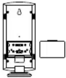
HOW TO INSTALL AND REPLACE BATTERIES IN THE TEMPERATURE STATION
natural_image
Simple line drawing of a vertical cylindrical device with internal components and a separate rectangular box on the right (no text or symbols)The temperature station uses 2 x AA, IEC LR6, 1.5V batteries. When batteries will need to be replaced, the low battery icon will appear on the LCD. To install and replace the batteries, please follow the steps below:
- Lift up the battery compartment cover.
- Insert batteries observing the correct polarity (see marking).
- Replace compartment cover.
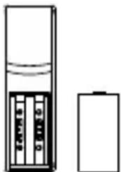
HOW TO INSTALL AND REPLACE BATTERIES IN THE TEMPERATURE TRANSMITTER
natural_image
Simple line drawing of a battery and an electronic device (no text or symbols)The temperature transmitter uses 2 x AA, IEC LR6, 1.5V battery. To install and replace the batteries, please follow the steps below:
- Remove the battery compartment cover at the back of the transmitter.
- Insert the batteries, observing the correct polarity (see marking).
- Replace the battery compartment cover on the unit.
Note:
In the event of changing batteries in any of the units, all units need to be reset by following the setting up procedures. This is because a security code is assigned by the transmitter at start-up and this code must be received and stored by the Temperature station in the first 3 minutes of power being supplied to it.
BATTERY CHANGE:
It is recommended to replace the batteries in all units regularly to ensure optimum accuracy of these units (Battery life See Specifications below).
Please participate in the preservation of the environment. Return used batteries to an authorised depot.
FUNCTION KEYS:
Temperature station:
The temperature station has four easy to use function keys.
text_image
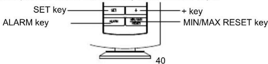
SET key + key ALARM key MIN/MAX RESET key 40SET key
- Press the key to enter manual setting modes: Time zone, Time reception ON/OFF and Manual time
- Stop the alarm
- Exit manual setting modes
+ key
- To make adjustment for various settings
- Stop the alarm
ALARM key
- Enter the alarm setting mode
- Switch the alarm ON/OFF
- Stop the alarm
MIN/MAX RESET key
- Press and hold to reset the MIN/MAX temperature records
- Activate the snooze
- Exit manual setting modes
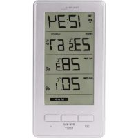
LCD SCREEN AND SETTINGS:
text_image
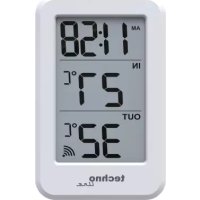
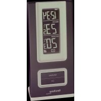
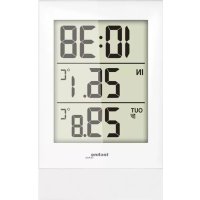
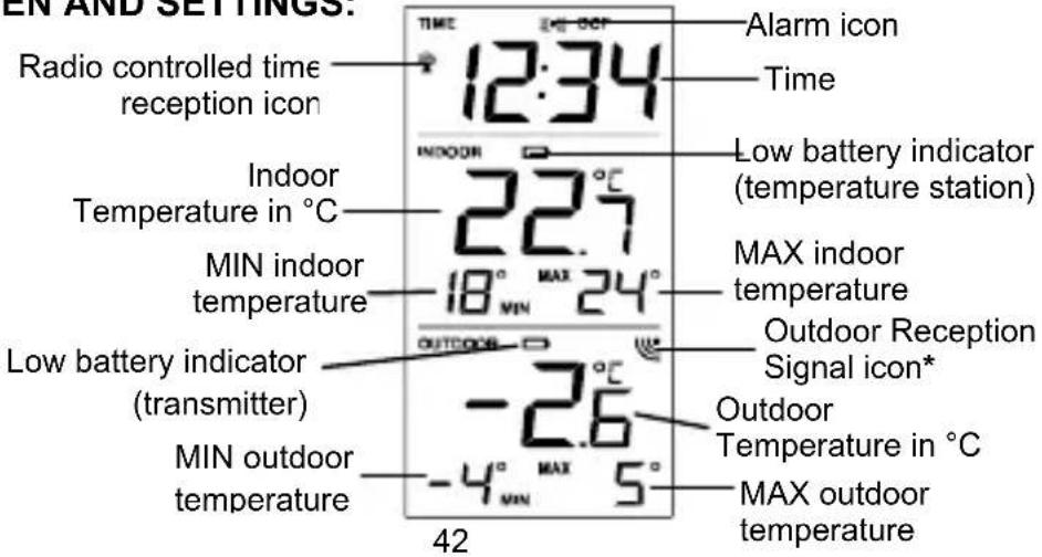
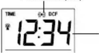
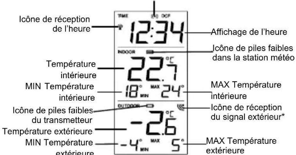
EN AND SETTINGS. Radio controlled time reception icon 12:34 Alarm icon Time Indoor Temperature in °C 22.7 INDOOR 18° MAX 24° Low battery indicator (temperature station) MAX indoor temperature Outdoor Reception Signal icon* Indoor temperature in °C MIN indoor temperature Outdoor Temperature in °C LOW battery indicator (transmitter) MIN outdoor temperature -2.6 -4° MAX 5° MAX outdoor temperature 42* When the outdoor signal is successfully received by the temperature station, this icon will be switched on. (If not successful, the icon will not be shown in LCD) So user can easily see whether the last reception was successful (icon on) or not (icon off).
For a better display clarity, the LCD screen is split into 3 sections.
Section 1 - TIME AND ALARM
- In normal mode display of radio controlled time
- A reception tower symbol will be shown indicating that the DCF-77 time signal is scanned for (flashing) or received (steady).
Note: The symbol will not be shown when radio time reception is not successful or when time reception function is turned off.
- In normal display, the alarm icon will be shown when the alarm is turned on. Or when the snooze function is activated, the alarm icon will be flashing.
Section 2 - INDOOR TEMPERATURE
- Display the current indoor temperature and indoor MIN/MAX records
- Display of low battery indicator (temperature station)
Section 3 - OUTDOOR TEMPERATURE
- Display the current outdoor temperature and outdoor MIN/MAX records
- A signal reception symbol will be shown indicating that receiver is receiving outdoor temperature
- Display of low battery indicator (transmitter)
MANUAL SETTINGS:
The following manual settings can be done in the setting mode:
- Time zone
• Time reception DCF ON/OFF - Manual time
Press and hold the SET key for about 3 seconds to advance to the setting mode:
TIME ZONE SETTING:
text_image
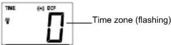
TIME (+) DCF Time zone (flashing)The time zone default is "0" hour. To set a different time zone:
- The current time zone value starts flashing.
- Use the + key to set the time zone. The range runs from 0, -1, -2...-12, 12, 11, 10... 2, 1, 0, in consecutive 1-hour intervals.
- Confirm with the SET key and enter the Time reception On/Off setting.
TIME RECEPTION ON/OFF SETTING
text_image
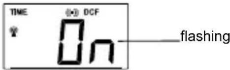
TIME DCF flashingIn area where reception of the radio-controlled time (DCF time) is not possible, the time reception function can be turned OFF. The clock will then work as a normal Quartz clock. (Default setting is ON).
- The digit "ON" digit will start flashing on the LCD.
- Use the + key to turn OFF the time reception function if necessary.
- Confirm with the SET key and enter the Manual time setting.
Note:
If the Time Reception function is turned OFF manually, the clock will not attempt any reception of the radio-controlled time (DCF time) as long as the Time Reception OFF function is activated. The Time Reception icon and the DCF icon will not be displayed on the LCD.
MANUAL TIME SETTING
In case the temperature station is not able to detect the radio-controlled time (DCF time) signal (disturbances, transmitting distance, etc.), the time can be manually set. The clock will then work as a normal Quartz clock.

text_image
Hours (flashing) TIME DCF 12:34 Minutes (flashing)To set the clock:
- The hour digits start flashing in the time display section.
- Use the + key to adjust the hours and then press SET key to go to the minute setting.
- The minute will be flashing. Press the + key to just the minutes.
- Confirm with the SET or MIN/MAX RESET key and exit the setting mode.
Note :
The unit will still try to receive the signal despite a manual setting. When the signal is received, the manually set time will automatically be replaced by the received time. During reception attempts, the DCF tower icon will flash. If reception has been unsuccessful, the DCF tower icon will not appear but reception will still be attempted.
ALARM SETTING
Alarm icon (ON)
text_image
TIME DCF 12:34To set alarm:
- Press and hold ALARM for about 3 seconds until the alarm time display flashes.
- The hour digit will be flashing and the alarm icon will appear. Press the + key to adjust the hour.
- Press ALARM button once and minute digit will be flashing. User shall then press + button to set the minute.
- Press ALARM button once to confirm the setting.
- To activate/ deactivate the alarm function, press the ALARM button once. The display of the alarm icon represents that the alarm is "ON".
Note: The duration of alarm sounding is 85 seconds
TO ACTIVATE THE SNOOZE FUNCTION AND STOPPING THE ALARM:
- When the alarm is sounding, press the MIN/MAX RESET key to activate the snooze function. The alarm will stop and re-activate after the snooze interval of 10 minutes.
- To stop the alarm completely, press any keys other than the MIN/MAX RESET key.
INDOOR TEMPERATURE AND MIN/MAX RECORDS
The indoor temperature and indoor MIN/MAX records are displayed on the second section of the LCD.
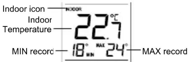
text_image
Indoor icon Indoor Temperature MIN record INDOOR 22.7°C 18° MAX 24° MIN record MAX recordNote: The MIN/MAX indoor temperature range is -9^ to +38^ with 1^ resolution.
OUTDOOR TEMPERATURE AND MIN/MAX RECORDS
The outdoor temperature and outdoor MIN/MAX records are displayed on the last section of the LCD. Outdoor icon
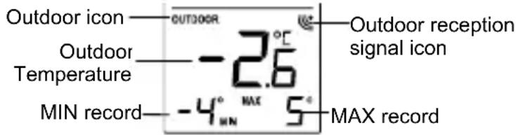
text_image
Outdoor icon Outdoor Temperature MIN record OUTDOOR -2.6° MAX 5° Outdoor reception signal icon MAX recordNote: The MIN/MAX outdoor temperature resolution range is -40^ to +60^ with 1^ resolution.
RESETTING THE INDOOR AND OUTDDOR MIN/MAX RECORDS
Note: All the MIN/MAX records will be reset at the same time.
- In normal display mode, press and hold the MIN/MAX RESET key for 3 seconds. This will reset the indoor and outdoor MIN/MAX temperatures.
LOW BATTERY INDICATOR
Low battery indicator is displayed on the LCD when the batteries require changing.
868 MHz RECEPTION CHECK
The temperature station should receive the temperature data within 3 minutes after setup. If the temperature data is not received 3 minutes after setting up (not successfully continuously, the outdoor display shows “- - -”), please check the following points:
- The distance of the temperature station or transmitter should be at least 1.5 to 2 meters away from any interfering sources such as computer monitors or TV sets.
-
Avoid positioning the temperature station onto or in the immediate proximity of metal window frames.
-
Using other electrical products such as headphones or speakers operating on the same signal frequency (868MHz) may prevent correct signal transmission and reception.
-
Neighbours using electrical devices operating on the 868MHz signal frequency can also cause interference.
Note:
When the 868MHz signal is received correctly, do not re-open the battery cover of either the transmitter or temperature station, as the batteries may spring free from the contacts and force a false reset. Should this happen accidentally then reset all units (see Setting up above) otherwise transmission problems may occur.
The transmission range is about 100 m from the transmitter to the temperature station (in open space). However, this depends on the surrounding environment and interference levels. If no reception is possible despite the observation of these factors, all system units have to be reset (see Setting up).
POSITIONING THE TEMPERATURE STATION:
The temperature station may be hung onto wall easily or free standing.
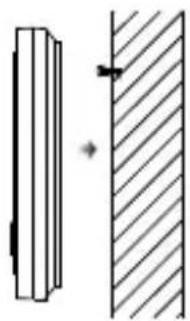
natural_image
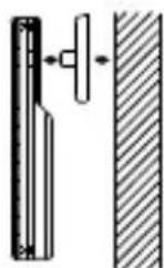
Pure diagram of two vertical bars with a diagonal hatching, no text or symbols presentTo wall mount
Choose a sheltered place. Avoid direct rain and sunshine.
Before wall mounting, please check that the outdoor temperature values can be received from the desired locations.
- Fix a screw (not supplied) into the desired wall, leaving the head extended out the by about 5mm.
- Remove the stand from the temperature station by pulling it away from the base and hang the station onto the screw. Remember to ensure that it locks into place before releasing.
text_image
12:34 22:7 -26Free standing
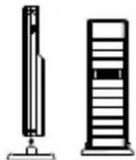
With the foldout stand, the temperature station can be placed onto any flat surface.
POSITIONING THE TEMPERATURE TRANSMITTER:
natural_image
Two vertical office chair designs, one upright and one tall, with no visible text or symbols.The transmitter is supplied with a holder that may be attached to a wall with the two screws supplied. The transmitter can also be position on a flat surface by securing the stand to the bottom to the transmitter.
To wall mount:
- Secure the bracket onto a desired wall using the screws and plastic anchors.
- Clip the remote temperature sensor onto the bracket.
Note:
Before permanently fixing the transmitter wall base, place all units in the desired locations to check that the outdoor temperature reading is receivable. In event that the signal is not received, relocate the
transmitters or move them slightly as this may help the signal reception.
CARE AND MAINTENANCE:
- Extreme temperatures, vibration and shock should be avoided as these may cause damage to the unit and give inaccurate forecasts and readings.
- Precautions shall be taken when handling the batteries. Injuries, burns, or property damage may be resulted if the batteries are in contact with conducting materials,
heat, corrosive materials or explosives. The batteries shall be taken out from the unit before the product is to be stored for a long period of time.
- Immediately remove all low powered batteries to avoid leakage and damage. Replace only with new batteries of the recommended type.
- When cleaning the display and casings, use a soft damp cloth only. Do not use solvents or scouring agents as they may mark the LCD and casings.
- Do not submerge the unit in water.
- Special care shall be taken when handling a damaged LCD display. The liquid crystals can be harmful to user's health.
- Do not make any repair attempts to the unit. Return them to their original point of purchase for repair by a qualified engineer. Opening and tampering with the unit may invalidate their guarantee.
- Never touch the exposed electronic circuit of the device as there is a danger of electric shock should it become exposed.
- Do not expose the units to extreme and sudden temperature changes, this may lead to rapid changes in forecasts and readings and thereby reduce their accuracy.
SPECIFICATIONS:
Recommended operating temperature range : 0°C to 50°C
Temperature measuring range:
Indoor : -9,9°C to +37,8°C with 0,1°C resolution
("OF.L" displayed if outside this range)
Outdoor : -39,9°C to +59,9°C with 0,1°C resolution
("OF.L" displayed if outside this range)
Indoor temperature checking interval : every 16 seconds
Outdoor data reception : every 4 seconds
Power consumption:
Temperature station : 2 x AA, IEC, LR6, 1.5V
Temperature transmitter : 2 x AA, IEC, LR6, 1.5V
Battery life cycle (Alkaline batteries recommended) : Approximately 24 months
Dimensions (L x W x H) :
Temperature station : 73,4 x 25,2 x 158 mm
Temperature transmitter : 38,2 x 21,2 x 128,3 mm
LIABILITY DISCLAIMER:
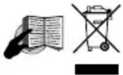
- The electrical and electronic wastes contain hazardous substances. Disposal of electronic waste in wild country and/or in unauthorized grounds strongly damages the environment.
- Please contact your local or/and regional authorities to retrieve the addresses of legal dumping grounds with selective collection.
• All electronic instruments must from now on be recycled. User shall take an active part in the reuse, recycling and recovery of the electrical and electronic waste. - The unrestricted disposal of electronic waste may do harm on public health and the quality of environment.
As stated on the gift box and labeled on the product, reading the "User manual" is highly recommended for the benefit of the user. This product must however not be thrown in general rubbish collection points.
- The manufacturer and supplier cannot accept any responsibility for any incorrect readings and any consequences that occur should an inaccurate reading take place.
• This product is designed for use in the home only as indication of the temperature and other weather data.
• This product is not to be used for medical purposes or for public information. The specifications of this product may change without prior notice.
- This product is not a toy. Keep out of the reach of children.
No part of this manual may be reproduced without written authorization of the manufacturer.
• Use the product only for its intended purpose!
natural_image
Illustration of an open book with a mouse, a crossed-out bicycle, and a black rectangular symbol (no text or labels)STATION DE TEMPERATURE 868 MHz
natural_image
Diagram of a vertical spring scale and a horizontal server tower, both without any text or symbols.natural_image
Simple line drawing of a vertical cylindrical device with internal components and a separate rectangular base (no text or symbols)natural_image
Diagram of a battery cell with internal components and external casing (no text or symbols)REEMPLACEMENT DES PILES:
text_image
Touche SET (réglage) Touche ALARM SET + ALARM MIN/MAX SET Touche + Touche MIN/MAX RESETTouche SET (Réglage):
ECRAN LCD ET REGLAGES:
text_image
Heures (clign.) TME 12:34 DCF Minutes (clign)TEMOIN DE PILES FAIBLES
natural_image
Diagram showing a vertical striped object and a diagonal hatched area with an arrow indicating direction (no text or symbols)
Sur un mur
natural_image
Technical line drawings of mechanical components including a spring scale, a vertical stack, and a cross-section with hatched fill (no text or symbols)natural_image
Diagram of a spring scale measuring a rectangular object, with no visible text or symbolsnatural_image
Technical line drawing of a mechanical device with internal components and a separate housing (no text or symbols)text_image
SET-toets ALARM-toets SET + ALARM MIN/MAX RESET + toets MIN/MAX RESFT-toets 99SET-toets (Handbediend regelen):
natural_image
Diagram showing a vertical panel with an arrow pointing to a shaded vertical surface (no text or symbols)Ophangen aan muur
natural_image
Two vertical server racks shown side by side, one with a cable and the other with a grid (no text or symbols visible)natural_image
Pure mechanical diagram showing a bracket and a vertical wall with diagonal hatching (no text or symbols)natural_image
Three black-and-white icons: a mouse pointing at an open book, a crossed-out electrical box with no visible text or symbolsnatural_image
Diagram of a vertical pump and a server rack (no text or symbols)natural_image
Technical line drawing of a mechanical device with internal components and a separate housing (no text or symbols)natural_image
Simple line drawing of a battery and its internal components (no text or symbols)text_image
TME [+] DCF T 0Lampeggiante