
ICM20H - Intercom Monacor - Free user manual and instructions
Find the device manual for free ICM20H Monacor in PDF.
User questions about ICM20H Monacor
0 question about this device. Answer the ones you know or ask your own.
Ask a new question about this device
Download the instructions for your Intercom in PDF format for free! Find your manual ICM20H - Monacor and take your electronic device back in hand. On this page are published all the documents necessary for the use of your device. ICM20H by Monacor.
USER MANUAL ICM20H Monacor
natural_image
Black desktop microphone with two speakers and a circular head cover (no text or symbols visible)ICM-20H
English ...... Page 7
Français ...... Page 10
Italiano.... Pagina 13
natural_image
Technical line drawing of two mechanical components with vertical and horizontal features (no text or symbols)Abb. 3 Klebemontage
4.2 Schraubmontage
natural_image
Technical diagram showing two mechanical assembly configurations with screws and fasteners (no text or symbols)These instructions are intended for the installers and users of the unit. Please read the instructions carefully prior to operation and keep them for later reference.
All operating elements and connections can be found on the fold-out page 3.
1 Operating Elements and Connections
1.1 Base station
1 Power supply jack for connection of the plug-in power supply unit
2 Selector switch for the microphone type: set the switch to EM (= electret microphone)
3 Jack MIC for connection of the red RCA plug (14) of the calling station
4 Jack SP for connection of the white RCA plug (15) of the calling station
5 Jack CALL-LAMP for connection of the 3.5 mm plug (16) of the calling station
6 Electret gooseneck microphone with applied pop protection
7 Connection for the gooseneck microphone
8 3.5 mm jack, 3 poles, for connection of stereo headphones
The speaker will be switched off when headphones are connected.
9 Power indicator
10 Volume control, combined with an on / off switch; when the control is engaged at the left stop (OFF), the system is switched off
11 TALK button, keep it pressed during an announcement
1.2 Calling station
12 Power indicator
13 CALL button, when the button is pressed, a signal sound will be triggered at the base station
14 Red RCA plug for connection to the jack MIC (3) of the base station
15 White RCA plug for connection to the jack SP (4) of the base station
16 3.5 mm plug for connection to the jack CALL-LAMP (5) of the base station
2 Safety Notes
The units correspond to all required directives of the EU and are therefore marked with .
WARNING
The power supply unit uses dangerous mains voltage. Leave servicing to skilled personnel only. Inexpert handling of the unit may result in electric shock.
- The units are suitable for indoor use only. Protect them against dripping water, splash water and high air humidity. The admissible ambient temperature range is 0–40°C.
- Do not set the system into operation, or immediately disconnect the power supply unit from the mains socket if
- there is visible damage to one of the units,
- a defect might have occurred after a drop or similar accident,
- malfunctions occur.
The units must in any case be repaired by skilled personnel. - For cleaning only use a dry, soft cloth, never use chemicals or water.
- No guarantee claims for the units and no liability for any resulting personal damage or material damage will be accepted if the units are used for other purposes than originally intended, if they are not correctly installed or operated, or if they are not repaired in an expert way.

If the units are to be put out of operation definitively, take them to a local recycling plant for a disposal which is not harmful to the environment.
3 Applications
The cable-connected intercom system ICM-20H is suitable e. g. for reception desks, counters, restaurants, etc. It consists of a base station with integrated amplifier, a calling station, and a plug-in power supply unit for the power supply. Mounting material for fixing the calling station is supplied with the system.
The base station has an integrated speaker with volume control, a removable gooseneck microphone, and a talk button. Headphones can be connected to improve intelligibility in noisy environments. The calling station, with integrated speaker and microphone, is connected via three cables to the base station. In addition, it is equipped with a calling button for triggering a signal sound.
4 Mounting the Calling Station
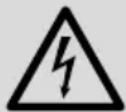
4.1 Mounting by glueing
Via the two supplied Velcro rings, the calling station can be glued to a glass pane.
1) Separate the rings which are connected with each other via Velcro fasteners. Both rings have a glueing layer on their rear side below a removable foil.
2) Remove the foil from one of the rings and glue the ring onto the rear side of the calling station.
3) Remove the foil from the second ring and glue the ring onto the desired place on the glass pane.
4) Attach the calling station with its Velcro ring to the Velcro ring on the glass pane.
natural_image
Technical line drawing of two mechanical components with vertical and horizontal features, no text or symbols presentFig. 3 Mounting by glueing
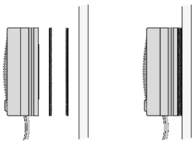
4.2 Mounting by screwing
Via the supplied screws, the calling station can be mounted to a thin partition (e. g. glass pane).
1) Drill a hole with a diameter of 50 mm at the partition.
2) Screw off the rear part of the calling station.
3) Loosen the rubber washer at the front part so that the connection cables can be removed from the lateral cable guidance. Then attach the washer again to the front part.
4) At the front, place the front part before the hole in the partition and guide the cables backwards through the hole.
5) Guide the cables through the rear part.
6) With the three longer screws supplied, screw the rear part to the front part.
natural_image
Technical diagram showing two mechanical assembly configurations with screws and fasteners (no text or symbols)Fig. 4 Mounting by screwing
5 Connection
1) Connect the gooseneck microphone (6) to the XLR jack (7) of the base station. The sliding switch (2) must be in position EM (= electret microphone).
2) Connect the three cables of the calling station to the matching jacks at the base station:
- the red RCA plug (14) to the red jack MIC (3)
– the white RCA plug (15) to the white jack SP (4)
- the 3.5 mm plug (16) to the 3.5 mm jack (5) CALL-LAMP
3) If required, connect stereo headphones to the 3.5 mm jack (8) on the left side of the base station. The speaker of the base station will be switched off.
Important: Never connect a mono earphone with a 2-pole plug to the jack. The 2-pole plug will cause a short-circuit and may thus damage the unit.
4) Connect the plug-in power supply unit to the power supply jack (1) of the base station and to a socket (230 V/50 Hz).
6 Operation
Switch on the system by turning up the control (10). The power indicators (9, 12) light up.
Audio transmission
calling station base station:
Go close to the calling station (optimum distance 10 to 20 cm) and talk. At the base station, adjust the volume of the speaker or headphones with the control (10). The person at the calling station can trigger a signal sound by pressing the button CALL (13).
CAUTION

Never adjust the headphones to a very high volume. Permanent high volumes may damage your hearing!
Audio transmission
base station calling station:
To make an announcement, keep the TALK button (11) pressed and talk into the goose-neck microphone (6). The announcement is reproduced via the speaker of the calling station. After the announcement, release the button.
To switch off the system, turn the control (10) counter-clockwise until it locks (position OFF). The system has a low power consumption even when it is switched off; therefore, disconnect the power supply unit from the mains when the system is not used for a longer period of time.
7 Specifications
Gooseneck microphone: . .electret microphone cartridge, cardioid, 300 mm gooseneck
Power supply: ........ --- 9 V/ 300 mA via supplied plug-in power supply unit (230 V/50 Hz/7 VA)
Ambient temperature: . . . 0–40 °C
Dimensions
Base station: 115 × 65 × 170 mm
Calling station: ..... 85 mm × 35 mm
Cable length:....3 m
Subject to technical modification.
Interphone
natural_image
Technical line drawing of two mechanical components with vertical and horizontal features, no text or symbols presentnatural_image
Technical diagram showing two mechanical assembly configurations with screws and fasteners (no text or symbols)natural_image
Technical line drawing of two mechanical components with vertical and horizontal features, no text or symbols presentnatural_image
Technical diagram showing two mechanical assembly configurations with screws and fasteners (no text or symbols)Fig. 4 Montaggio a vite