
SAM-500D - Subwoofer Monacor - Free user manual and instructions
Find the device manual for free SAM-500D Monacor in PDF.


| Product type | Active subwoofer |
| Brand | Monacor |
| Model | SAM-500D |
| RMS power | 500 W |
| Power supply | Mains 230 V ~ 50 Hz |
| Dimensions (W x H x D) | 500 x 400 x 400 mm |
| Weight | 20 kg |
| Frequency response | 30 – 150 Hz |
| Speaker | 1 x 300 mm (12 inches) |
| Inputs | Balanced line XLR / 6.35 mm jack |
| Outputs | XLR output (loop-through) |
| Controls | Volume, low-pass filter, phase (0/180°) |
| Protection | Limiter and thermal protection |
| Care and cleaning | Clean with a soft, dry cloth. Do not use abrasive products. |
| Safety instructions | Do not expose to moisture or splashes. Disconnect before maintenance. |
| Spare parts and repairability | Speaker and amplifier module replaceable. Access via rear panel. |
| Intended use | Professional sound reinforcement, home cinema |
Frequently Asked Questions - SAM-500D Monacor
User questions about SAM-500D Monacor
0 question about this device. Answer the ones you know or ask your own.
Ask a new question about this device
Download the instructions for your Subwoofer in PDF format for free! Find your manual SAM-500D - Monacor and take your electronic device back in hand. On this page are published all the documents necessary for the use of your device. SAM-500D by Monacor.
USER MANUAL SAM-500D Monacor
1 Operating Elements and Connections ..... 8
2 Safety Notes....9
3 Applications....9
4 Installation and Connection 9
4.1 Connecting a signal source 10
4.2 Signal output.... 10
4.3 Power supply 10
5 Operation....10
6 Specifications.... 11
Français
These instructions are intended for non-professionals with basic knowledge in DIY speaker building. Please read the instructions carefully prior to operation and keep them for later reference.

1 Operating Elements and Connections
1 Status LED red = standby green = power amplifier switched on
2 LEVEL control
3 CUT OFF control to set the cut-off frequency for the subwoofer
4 PHASE control to shift the phase of the output signal compared to the input signal
5 Input LINE IN (RCA jacks) for signals with line level; when both jacks are connected (e. g. stereo signal), the signals internally create a sum signal (mono)
6 Output LINE OUT (RCA jacks) to route the input signal e. g. to another amplifier
7 Screw terminals HIGH LEVEL INPUT as a signal input to connect the speaker outputs of a power amplifier [instead of using the RCA jacks LINE IN (5)]
8 POWER switch
9 Mains jack for connection to a socket (230 V/ 50 Hz) via the mains cable provided
10 Support for the mains fuse
Always replace a blown fuse by one of the same type.
2 Safety Notes
The amplifier module corresponds to all relevant directives of the EU and is therefore marked with €€
WARNING
The module uses dangerous mains voltage. Install the module before connecting it to the mains; otherwise you will risk an electric shock.
- The module is suitable for indoor use only. Protect it against dripping water and splash water, high air humidity and heat (admissible ambient temperature range 0–40°C).
-
Do not operate the module or immediately disconnect the mains plug from the socket
-
if the module or the mains cable is visibly damaged,
- if a defect might have occurred after the unit was dropped or suffered a similar accident,
- if malfunctions occur.
In any case the module must be repaired by skilled personnel.
- Never pull the mains cable to disconnect the mains plug from the socket, always seize the plug.
- For cleaning only use a dry, soft cloth; never use water or chemicals.
- No guarantee claims for the module and no liability for any resulting personal damage or material damage will be accepted if the module is used for other purposes than originally intended, if it is not correctly installed or operated, if it is modified or if it is not repaired in an expert way.

If the module is to be put out of operation definitively, take it to a local recycling plant for a disposal which is not harmful to the environment.
3 Applications
This amplifier module is designed for installation into a subwoofer speaker cabinet which is used to complement existing speaker systems with low frequencies when a convincing bass reproduction is required.
The module is provided with a low-pass filter with adjustable cut-off frequency (40 - 200 Hz) and a control to correct the phase in combination with other speakers. The amplifier has a limiter to protect the speaker.
The power amplifier is designed as a class D amplifier. It is supplied with power from a switch-mode power supply. Thus, it has an extra high efficiency at a low weight.
Instead of connecting the module to signal sources with line level, it is also possible to connect it to the speaker outputs of a power amplifier.
4 Installation and Connection
WARNING
When installing the amplifier module, always disconnect it from the mains. For operation, the module must always be installed; otherwise you will risk an electric shock.
1) To install the module, saw a suitable cutout (approx. 225 mm × 248 mm) into the speaker cabinet.
2) Only connect speakers or speaker systems with a total impedance of at least 4 Ω. Connect the speaker via the two cables coming from the PCB. Always observe the correct polarity: connect the positive pole of the speaker to the red cable (marked "SP+" on the PCB); connect the negative pole to the black cable (marked "SP-" on the PCB).
3) Insert the module into the speaker cabinet. Make sure that there is sufficient space for the module inside the cabinet and that there is no risk of contact with other electroconductive components or heat-sensitive materials. When the front plate is not recessed, the required mounting depth is 76 mm. Do not stretch or squeeze the connection cables.
4) Use eight screws ( 4 mm) to fasten the front plate of the module to the cabinet.
5) When setting up a single subwoofer, it is not important to place the subwoofer exactly in the middle between the stereo speakers as it will not be possible to precisely locate the very low frequencies reproduced by the subwoofer. However, do not place it too close to walls or in corners; this would distort the frequency response.
Prior to making connections or changing any existing connections, switch off the amplifier module and the units to be connected.
4.1 Connecting a signal source
Connect a signal source with line level (e. g. output of a mixer or preamplifier) to the RCA jacks LINE IN (5). When connecting a stereo signal source, a mono signal is internally created. It is also possible to connect the jack L / LFE to an LFE output. In multi-channel systems for cinema applications, e. g. "5.1", the LFE channel is used for low-frequency special effects ("Low Frequency Effect" or "Low Frequency Enhancement").
Alternatively, connect the screw terminals HIGH LEVEL INPUT (7) to the speaker outputs of a power amplifier [in parallel to the speakers connected there]. Connect the left channel to the terminal pair "L", connect the right channel to "R". Observe the correct polarity: Always connect the positive pole (marked core of speaker cable) to the red terminal.
Caution!
- Only connect amplifiers with a maximum output voltage of 2 × 20 V (corresponding to an output power of 2 × 100 W at 4 Ω or 2 × 50 W at 8 Ω ) to these terminals.
- When connecting the screw terminals, make sure that the cable ends are only stripped for the length required and that no bare wires protrude (hazard of contact and short circuit).
4.2 Signal output
At the RCA jacks LINE OUT (6), the input signal is available for being routed to another amplifier or active speaker system. The position of the controls LEVEL (2), CUT OFF (3) and PHASE (4) has no effect on this output signal.
4.3 Power supply
Connect the mains cable provided to the mains jack (9) and the plug to a mains socket (230V/50Hz).
5 Operation
CAUTION

Never adjust the speaker system to a very high volume. Permanent high volumes may damage your hearing! Your ear will get accustomed to high volumes which do not seem to be that high after some time. Therefore, do not further increase a high volume after getting used to it.
Note: To prevent switching noise, always switch on the signal source connected before switching on the amplifier module. After use, switch off the amplifier module first.
1) Before switching on for the first time, set the LEVEL control (2) to minimum (left stop) for the time being. Switch on the amplifier with the POWER switch (8). As long as no signal is applied, the module is on standby to save power and the LED STANDBY/POWER (1) shows red. As soon as a signal is applied, the power amplifier is switched on and the LED shows green.
2) Via the existing speaker system, reproduce music, for example, and add the desired low bass part with the LEVEL control (2). Only turn up the control to such an extent that the sound reproduced is not distorted.
3) Use the control CUT OFF (3) to set the upper cut-off frequency of the subwoofer in such
a way that it will optimally complement the frequency response of the other speakers.
4) When the speakers are placed at different distances to the listener, phase cancellation may result (certain frequencies are reproduced at a lower volume). To compensate this effect, shift the phase of the subwoofer signal with the control PHASE (4).
Test the positions of the control to find the one offering the bass reproduction of the highest volume at the listening position. Then readjust the volume balance with the LEVEL control (2), if required.
5) If there is no signal at the input for more than approx. 25 minutes, the amplifier module goes on standby: The LED STANDBY / POWER (1) shows red. If the amplifier module is not in use for longer intervals, switch off the amplifier module with the POWER switch.
6 Specifications
Amplifier power at 4 Ω / 8 Ω
RMS power: ..... 500W/250W
Peak power: ..... 700W/350W
Frequency range
(upper cut-off frequency
is variable): ..... 20–40 ... 200 Hz
Load impedance: ..... 4–8Ω
Input impedance
LINE IN: 22 kΩ
HIGH LEVEL INPUT: .. 270Ω
Input sensitivity
LINE IN: 170mV
HIGH LEVEL INPUT: .. 1 V
Input voltage max.
LINE IN: 7V
HIGH LEVEL INPUT: .. 20V
THD: .... < 1 %
S/N ratio: .... > 70 dB
Power supply: ..... 230 V/50 Hz
Power consumption
Full load: 840 VA
No-load: 38 VA
Standby: 0.5 W
Ambient temperature: . 0–40°C
Dimensions: ......251×270×90 mm
Weight: 2.5kg
Subject to technical modification.


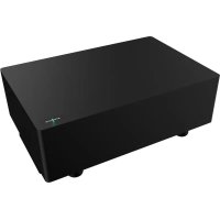
Brand : Monacor
Model : SAM-500D
Category : Subwoofer