SUBWS - Subwoofer Monacor - Free user manual and instructions
Find the device manual for free SUBWS Monacor in PDF.
| Product Type | Active wireless subwoofer |
| Brand | Monacor |
| Model | SUBWS |
| Category | Subwoofer |
| Wireless technology | RF 1.8 - 1.9 GHz |
| Power supply | 230 V ~ 50 Hz (Class I) |
| Power (estimated) | 100 W RMS |
| Frequency response (estimated) | 30 - 150 Hz |
| Dimensions (W x H x D, estimated) | 300 x 300 x 400 mm |
| Weight (estimated) | 10 kg |
| Main functions | Wireless audio transmission, automatic standby, overload protection |
| Maintenance and cleaning | Unplug before cleaning; use a dry, soft cloth |
| Safety | Do not expose to water or moisture; do not open; grounding required |
| Spare parts and repairability | No user-serviceable parts; refer all repairs to qualified personnel |
| General information | Compliant with FCC and IC; minimum distance of 20 cm between device and body |
Frequently Asked Questions - SUBWS Monacor
User questions about SUBWS Monacor
0 question about this device. Answer the ones you know or ask your own.
Ask a new question about this device
Download the instructions for your Subwoofer in PDF format for free! Find your manual SUBWS - Monacor and take your electronic device back in hand. On this page are published all the documents necessary for the use of your device. SUBWS by Monacor.
USER MANUAL SUBWS Monacor
1 Important remarks Page 4
2 Important safety instructions Page 6
3 Introduction Page 8
4 Setting up
5 Packaging content Page 13
6 Technical specifications Page 14
7 Compliance & License
1. IMPORTANT REMARKS

WARNING
Risk of electric shock Do not open
AVIS
The lightning flash with arrowhead symbol, within an equilateral triangle, is intended to alert the user to the presence of uninsulated "dangerous voltage" within the product's enclosure that may be of sufficient magnitude to constitute a risk of electric shock to persons.

The exclamation point within an equilateral triangle is intended to alert the user to the presence of important operating and maintenance (servicing) instructions in the literature accompanying the appliance.
WARNING
(If applicable): The terminals marked with symbol of " " may be of sufficient magnitude to constitute a risk of electric shock. The external wiring connected to the terminals requires installation by an instructed person or the use of ready-made leads or cords.
WARNING
To prevent fire or shock hazard, do not expose this equipment to rain or moisture.

Class I (1) appliance
WARNING
This product must not be discarded, under any circumstance, as unsorted urban waste.
Take to the nearest electrical and electronic waste treatment centre.

NOTE
Spottune company accepts no liability for any damage that may be caused to people, animal or objects due to failure to comply with the warnings above.
1. REMARQUES IMPORTANTES
WARNING
Risk of electric shock Do not open
AVIS
- Read these instructions.
- Keep these instructions.
- Heed all warnings.
- Follow all instructions.
- Do not use this apparatus near water.
- Clean only with dry cloth.
- Install in accordance with the manufacturer's instructions, and avoid covering the control panel as this can cause overheating.
- Do not install near any heat sources such as radiators, heat registers, stoves, or other apparatus (including amplifiers) that produce heat.
- Protect the power cord from being walked on or pinched particularly at the plugs, convenience receptacles, and at the point where they exit from the apparatus.
- Only use attachments/accessories specified by the manufacturer.
- Unplug the apparatus during lightening shorts or when unused for long periods of time.
- Refer all servicing to qualified personnel. Servicing is required when the apparatus has been damaged in any way, such as power supply cord or plug is damaged, liquid has been spilled or objects have fallen into the apparatus, the apparatus has been exposed to rain or moisture, does not operate normally, or has been dropped.
- Equipment is connected to a socket-outlet with earthing connection by means of a power cord.
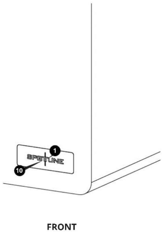
- The marking information is located at the bottom of apparatus.
- The apparatus shall not be exposed to dripping or splashing and that no objects filled with liquids, such as vases, shall not I be placed on the apparatus.
2. CONSIGNES DE SECURITE IMPORTANTES
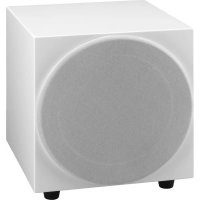
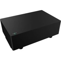
Spottune SUB is a wireless subwoofer, designed to be set up in minutes and used in combination Spottune Omni speakers, and addition to your spottune system
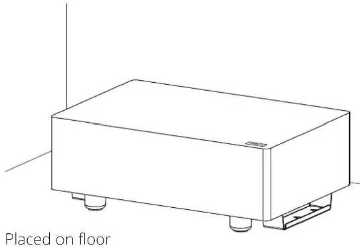
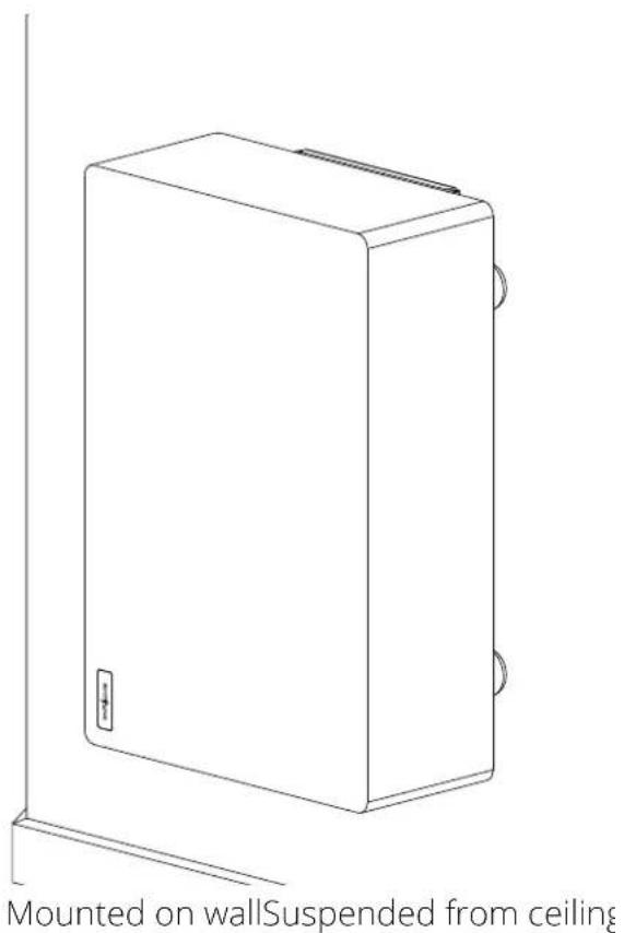
The Subwoofer can be placed on the floor, wall or ceiling mounted, and is wirelessly connected to Spottune stream.
Instructions for wall mounting, can be found on page 11
Instructions for ceiling installation, can be found on page 12
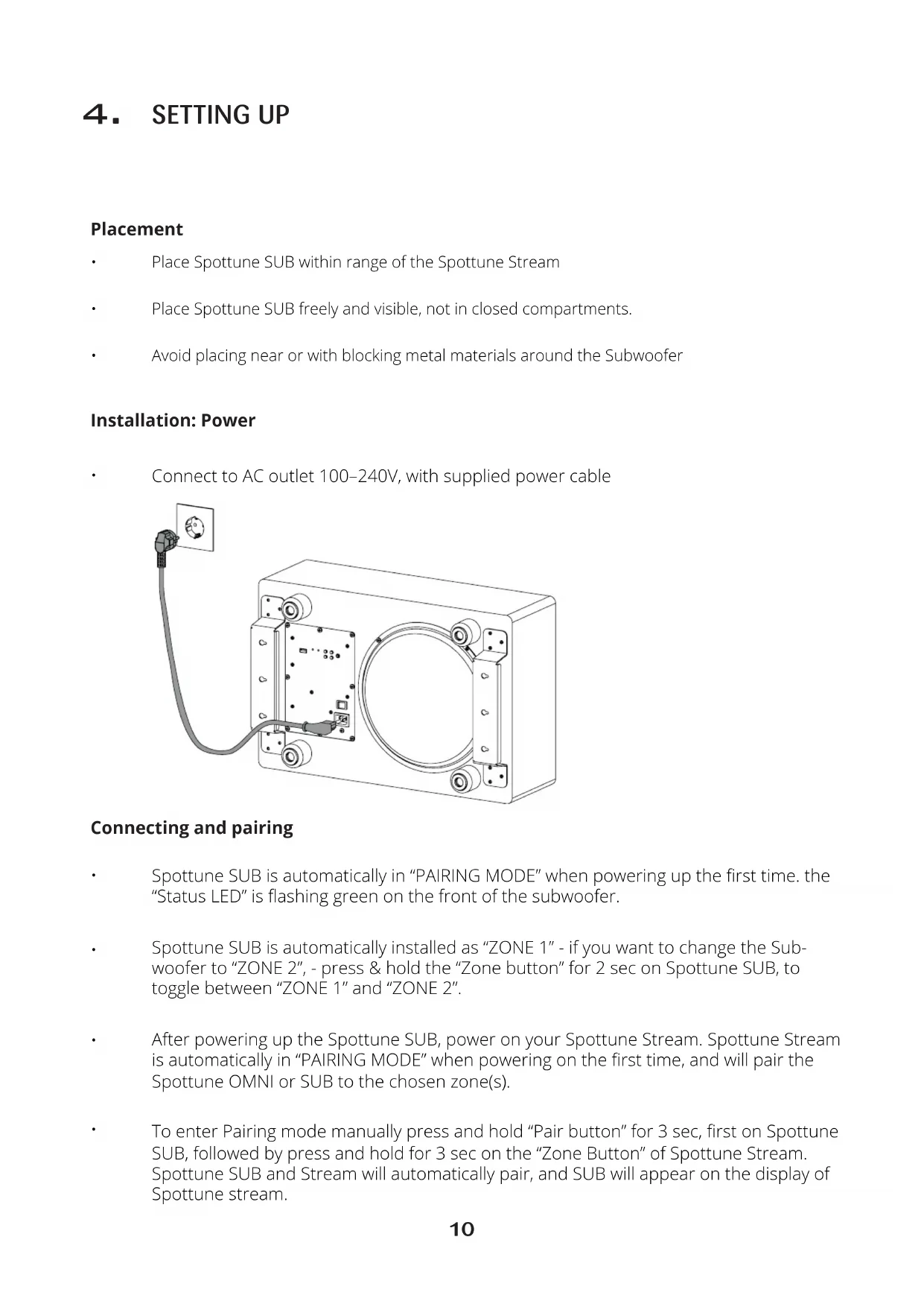
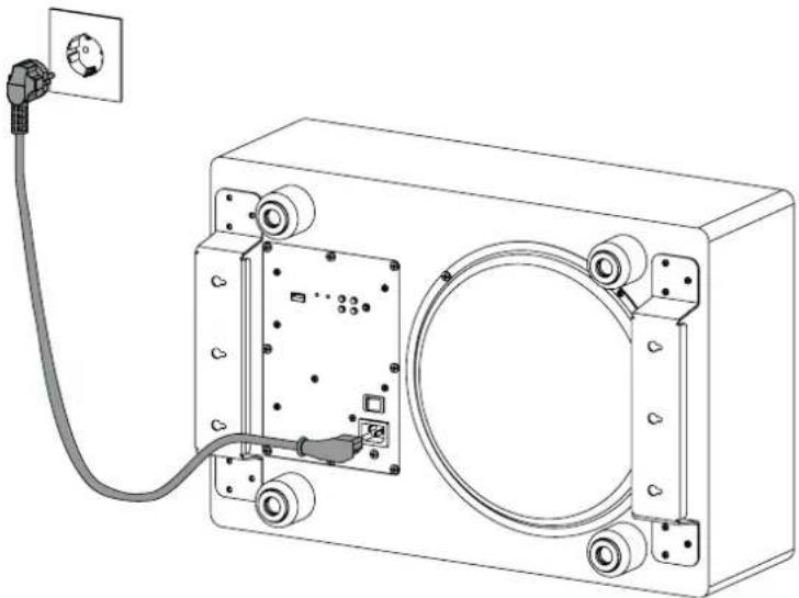
- Status LED
- USB Port for service, and update
- Zone indicator. LED lights to indicate if SUB is connected to zone I or II
- Zone button. Switch between zone I and II
- Pair button. For pairing subwoofer with Spottune Stream - Transmitter
- Volume buttons
- AUX input
- On/off button
- Power inlet
- Microphone
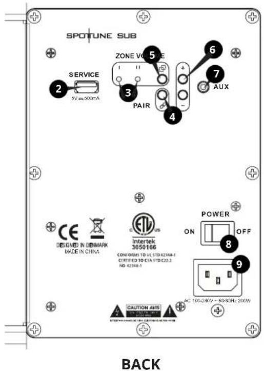
STATUS LED Lights
No light No power connected to the Subwoofer
WHITE light Booting up
GREEN flash Subwoofer is in pairing mode / process
GREEN light Connection established / ready
RED flash No connection to Spottune Stream
RED light Standby, no music signal from stream.
YELLOW flash Reset to factory default
4. SETTING UP
Placement
- Place Spottune SUB within range of the Spottune Stream
Place Spottune SUB freely and visible, not in closed compartments. - Avoid placing near or with blocking metal materials around the Subwoofer
Installation: Power
- Connect to AC outlet 100-240V, with supplied power cable
Connecting and pairing
Spottune SUB is automatically in "PAIRING MODE" when powering up the first time. the "Status LED" is flashing green on the front of the subwoofer.
Spottune SUB is automatically installed as "ZONE 1" - if you want to change the Subwoofer to "ZONE 2", - press & hold the "Zone button" for 2 sec on Spottune SUB, to toggle between "ZONE 1" and "ZONE 2".
After powering up the Spottune SUB, power on your Spottune Stream. Spottune Stream is automatically in "PAIRING MODE" when powering on the first time, and will pair the Spottune OMNI or SUB to the chosen zone(s).
- To enter Pairing mode manually press and hold "Pair button" for 3 sec, first on Spottune SUB, followed by press and hold for 3 sec on the "Zone Button" of Spottune Stream. Spottune SUB and Stream will automatically pair, and SUB will appear on the display of Spottune stream.
Volume control
The volume level of Spottune SUB can be adjusted either through Spottune Cloud, or manually by using the "Volume buttons" on the back of the subwoofer.
Factory Reset
- Press "Zone button" on Spottune SUB and hold for 30 seconds to factory reset the subwoofer. The "Status LED" will flash yellow to confirm the reset.
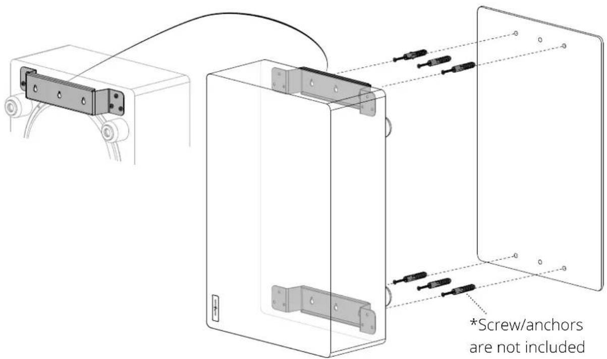
Mounting: Wall
WARNING WHEN INSTALLING, ALWAYS OBSERVE THE NATIONAL INSTALLATION AND ACCIDENT PREVENTION REGULATIONS
NOTE: DO ALL SETTINGS ON REAR PANEL, BEFORE MOUNTING SUB TO ITS PLACE.
Using the mounting template, place and mark up holes. Find suitable screws and wall anchors, (see minimum requirements below), and mount the screws in the wall. Mount the SUB by placing the premounted wallbrackets on the screws. Make sure the subwoofer is mounted solid. Thighten screws if necessary.
Minimum requirements for wall mounting:
Anchors: suitable for wall, minimum requirement 10kg per anchor
Screws: minimum requirement 10kg per screw
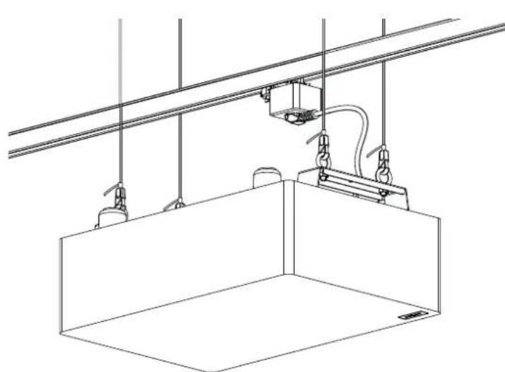
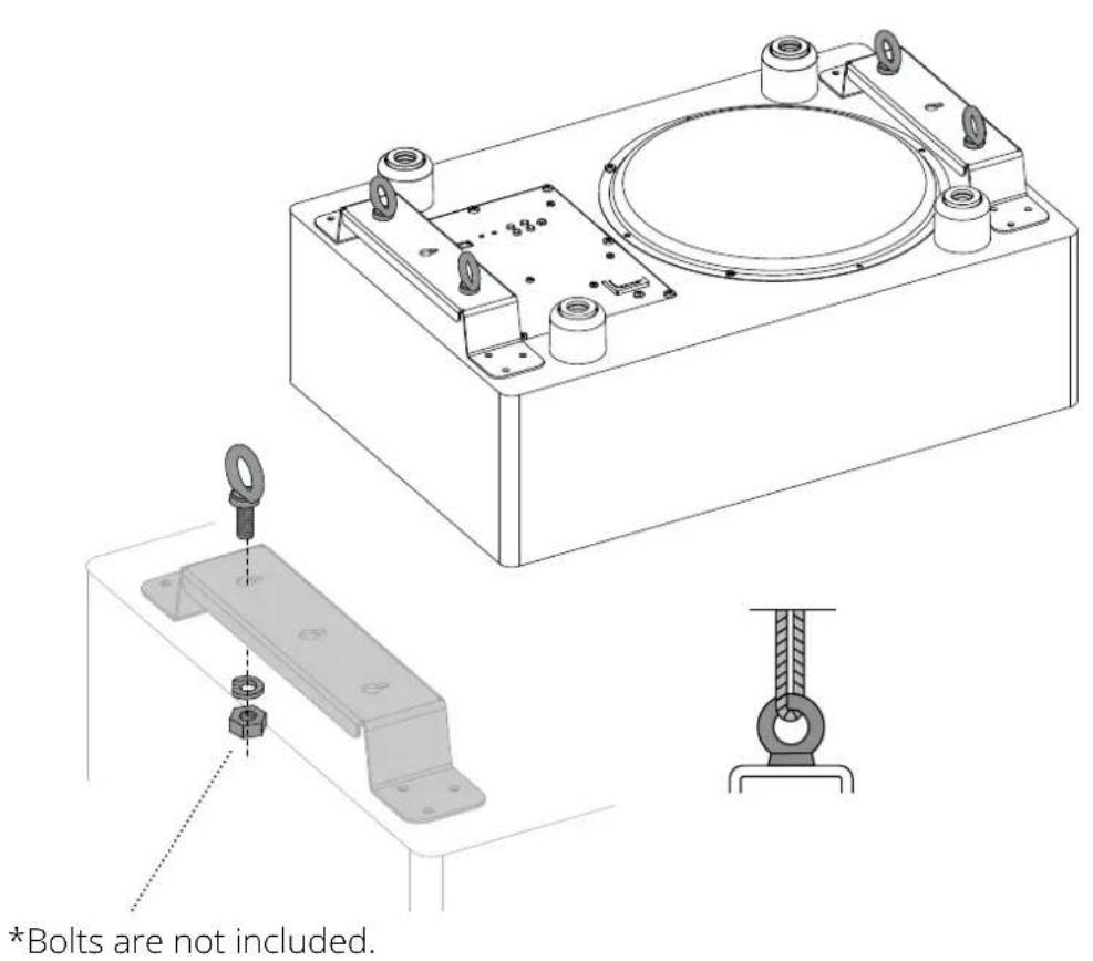
Mounting:Ceiling
WARNING WHEN INSTALLING, ALWAYS OBSERVE THE NATIONAL INSTALLATION AND ACCIDENT PREVENTION REGULATIONS
IMPORTANT ALWAYS CONSULT WITH A PROFFESIONAL INSTALLER.
Utilizing the wall brackets in combination with eye/ring-bolts, enables the possibility of hanging the Spottune Sub from the ceiling, in a wire hanging system.
Find ring/eye-bolts, split lock washers, lock nuts, wires and ceiling anchors, suitable for the ceiling type vs weight of Spottune Sub.
Place and mount 4x ring-bolts in each corner of the premounted wall-brackets. Remember to use locking washer and lock nuts (illustration 1).
Minimum requirements for mounting suspended from the ceiling:
Ring-bolt: M8, minimum requirement 20 kg per bolt
Wire system: minimum requirement 20kg per wirev
Ceiling anchors: minimum requirement 20kg per anchor
5. PACKAGING CONTENT
Spottune SUB packaging contains:
Spottune SUB
User Manual
Mounting template (For wall mounting)
Schuko - IEC powercord
NOTE: Screws, anchors, and etc. for wall and ceiling installation are not included
6. TECHNICAL SPECIFICATIONS
Colors
White / Black / Grey
Specifications
Wireless Smart Subwoofer
200 Watt high efficiency digital Class-D power amplification
10 Inch (250 mm) long stroke driver with extended linear excursion.
Microphone sound level accessed from Stream & Cloud
Closed box design for optimum performance and extended low-frequency performance.
Frequency
Audio frequency range 20-200Hz
Cutoff variable low pass digital filters:
60, 80, 100, 120, 160 and 200Hz controlled by
Stream & Cloud
Amplification
200W class D amplifier
Max SPL 100dB
Wireless Features
Audio-BroadCasting-Digital - Technology
Range up to 50-100m (Condition dependent)
Controls
Wireless input
Volume, Zone 1 & 2
AUX input
Dimensions
Height: 200mm
Width: 360mm
Length: 540 mm
Weight
12 Kg
Standby power consumption
1,4W
SKU
W1-F-B, W1-F-G, W1-F-W
7. COMPLIANCE & LICENSE
This device complies with Part 15 of the FCC Rules. Operation is subject to the following two conditions:
- This device may not cause harmful interference, and -
- This device must accept any interference received, including interference that may cause undesired operation.
NOTE: This product has been tested and found to comply with the limits for a Class B digital device, pursuant to Part 15 of the FCC Rules. These limits are designed to provide reasonable protection against harmful interference in a residential installation. This product generates, uses, and can radiate radio frequency energy and, if not installed and used in accordance with the instructions, may cause harmful interference to radio communications. However, there is no guarantee that interference will not occur in a particular installation. If this product does cause harmful interference to radio or television reception, which can be determined by turning the equipment off and on, the user is encouraged to try to correct the interference by one or more of the following measures:
- Reorient or relocate the receiving antenna.
-
Increase the separation between the equipment and receiver.
-
Connect the equipment into an outlet on a circuit different from that to which the receiver is connected.
- Consult the dealer or an experienced radio/TV technician for help.
Please take attention that changes or modification not expressly approved by the party respon- sible for compliance could void the user's authority to operate the equipment.
NOTE: This device contains licence-exempt transmitter(s)/receiver(s) that comply with Innovation, Science and Economic Development Canada's licence-exempt RSS(s). Operation is subject to the following two conditions:
- This device may not cause interference.
- This device must accept any interference, including interference that may cause undesired operation of the device.
Limited by local law regulations, version for North America does not have region selection option.
This equipment complies with FCC/IC RSS-102 radiation exposure limits set forth for an uncontrolled environment. This equipment should be installed and operated with minimum distance 20cm between the radiator & your body.