
CS-50DU - Microphone Monacor - Free user manual and instructions
Find the device manual for free CS-50DU Monacor in PDF.


| Product Type | Dynamic Microphone |
| Brand | Monacor |
| Model | CS-50DU |
| Recommended Use | Live sound, studio recording |
| Connector | XLR 3-pin |
| Frequency Response | 50 Hz - 15 kHz |
| Impedance | 600 Ω balanced |
| Sensitivity | -54 dB ± 3 dB (0 dB = 1V/Pa) |
| Power | 48V phantom power (not required for dynamic) |
| Dimensions (L x Ø) | 180 mm x 50 mm |
| Weight | 320 g |
| Housing Material | Robust metal |
| Grille | Steel grille with integrated pop filter foam |
| Included Accessories | Stand clamp, XLR cable, carrying case |
| Polar Pattern | Cardioid |
| Maintenance | Clean the grille with a soft, dry cloth |
| Safety | Do not expose to moisture or severe shocks |
| Repairability | Repair by qualified technician recommended |
Frequently Asked Questions - CS-50DU Monacor
User questions about CS-50DU Monacor
0 question about this device. Answer the ones you know or ask your own.
Ask a new question about this device
Download the instructions for your Microphone in PDF format for free! Find your manual CS-50DU - Monacor and take your electronic device back in hand. On this page are published all the documents necessary for the use of your device. CS-50DU by Monacor.
USER MANUAL CS-50DU Monacor
CS-50 CU CS-50 CH CS-50DU
Best.-Nr. 17.3420
Best.-Nr. 17.3410
Best.-Nr. 17.3430
BEDIENUNGSANLEITUNG
INSTRUCTION MANUAL
MODE D'EMPLOI
ISTRUZIONI PER L'USO
GB Before switching on ...
We wish you much pleasure with your new MONACOR unit. Please read these operating instructions carefully prior to operating the unit. Thus, you will get to know all functions of the unit, operating errors will be prevented, and yourself and the unit will be protected against any damage caused by improper use. Please keep the operating instructions for later use.
The English text starts on page 10.
3 = Audiosignal (Lautsprecher)
4 = Steuerleitung 1
5 = Steuerleitung 2
6 = Versorgung +15 V
7 = Versorgung -15 V
Stromversorgung: ..... 100 – 264 V\~/50 – 60 Hz
1 Operating Elements and Connections
1.1 Controller CS-50CU (upper side)
1 Speaker
2 Headphone output as a 3.5 mm jack; if a plug is connected to this jack, the speaker (1) will be switched off
3 Volume control for the headphone jack (2) and the speaker (1)
4 Control (rotary switch with 11 positions) for the volume of all speakers and the maximum volume of all headphones on the controller and on all microphone stations
5 Display
6 Button ▲o start and stop the stopwatch feature in the setting menu: to select the operating mode and to change a setting
7 Button ☑ to reset the stopwatch feature (when counting is stopped)
in the setting menu: to select the operating mode and to change a setting
8 Button SET
short actuation: to switch over between the indication of date/time and the stopwatch mode; longer actuation (approx. 2 seconds) to activate the setting menu in the setting menu: to confirm a menu item selected or a setting
9 POWER switch ①
1.2 Controller CS-50CU (rear side)
10 Mains switch for connection to a mains socket (230 V\~/ 50 Hz) via the cable provided
11 Support for the mains fuse;
replace a fuse that has blown by one of the same type only
12 Selector switch to route the audio signals via a unit for signal processing connected (e. g. equalizer) to the jacks "Insertion" (14)
position "I": unit inserted into the signal path
position "O": unit not inserted into the signal path
13 RCA jacks "Telephone" with input (in) and output (out) to connect a telephone system via a telephone coupler
14 RCA jacks "Insertion" with input (in) and output (out) to insert a unit for external signal processing (e.g. equalizer) into the signal path
15 RCA jacks "Recorder" with input (in) and output (out) to connect a recorder; the jacks are available for the left (L) channel and right (R) channel respectively of a stereo recorder; however, signal
processing in the conference system will be monophonic
16 RCA jacks "Line" with input (in) to connect a signal source with line output level and output (out) to connect an amplifier system
17 Control "Gain" to adjust the input amplification for the inputs "Recorder in" (15)
18 Control "Gain" to adjust the input amplification for the microphone input (20)
19 Jacks "Trunk in/out" 1 and 2 to connect the microphone stations; each of the two jacks will allow connection of a chain of up to 25 microphone stations CS-50CH and/or CS-50DU
20 Microphone input as an XLR jack; the input will supply a phantom power of 12 V; therefore, connect microphones with balanced output only!
1.3 Microphone station CS-50CH (CS-50DU)
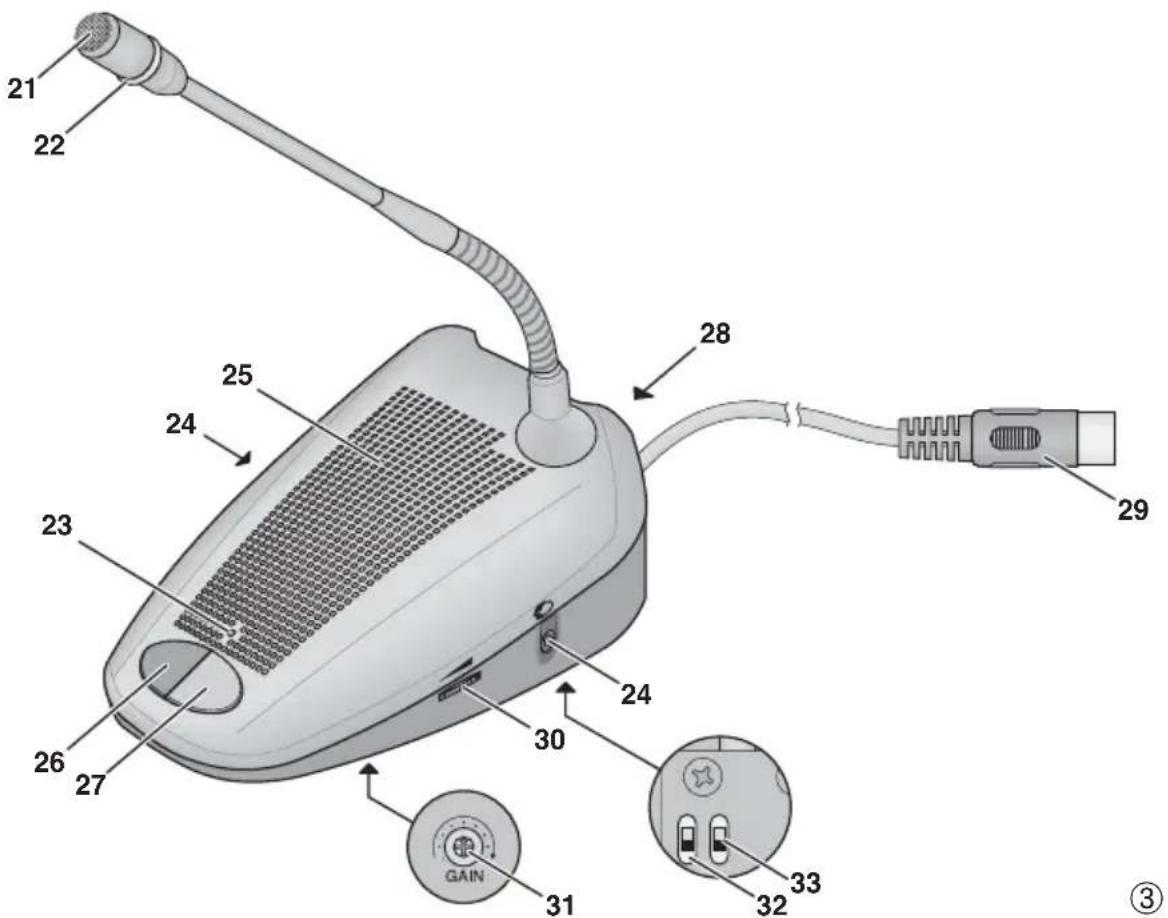
Figure 3 shows the microphone station CS-50CH (for the chairperson); deviations from the microphone station CS-50DU (for delegates) are described in the corresponding operating elements.
21 Microphone
22 Ring; will light up when the microphone is switched on or when a system test is performed (chapter 5.7)
23 LED; will light up when the microphone is switched on or when a system test is performed (chapter 5.7)
24 Two 3.5 mm jacks to connect headphones; if a plug is connected to one of these jacks, the speaker (25) will be switched off
25 Speaker
26 for CS-50CH only: Priority button for the chairperson to interrupt a discussion between delegates
27 Talk button to switch on/off the microphone
28 Jack to connect the next microphone station
29 Plug for connection to one of the jacks "Trunk in/out" (19) on the controller or to the jack (28) of another microphone station
30 Volume control for the headphone outputs (24)
31 Control GAIN to adjust the microphone amplification
32 for CS-50CH only: Switch for the automatic acoustic signal which will sound when an announcement is interrupted; the acoustic signal will be audible when the switch is in the upper position
33 for CS-50CH only: Switch to define the behaviour after interrupting an announcement
lower position: microphones of stations which had been switched on before the interruption will be automatically switched on again after the interruption
upper position: after an interruption, the microphones of all delegate stations will remain switched off
2 Safety Notes
The units (the controller CS-50CU and the microphone stations CS-50DU/CS-50CH) correspond to all relevant directives of the EU and are therefore marked with CC.
WARNING
The controller uses dangerous mains voltage. Leave servicing to skilled personnel only. Inexpert handling or modification of the unit may result in electric shock.
Please observe the following items in any case:
- The units are suitable for indoor use only. Protect them against dripping water and splash water, high air humidity and heat (admissible ambient temperature range 0 – 40 °C).
- Do not place any vessel filled with liquid on the units, e. g. a drinking glass.
- The heat generated inside the controller must be dissipated by air circulation; never cover the air vents.
-
Do not operate the controller and immediately disconnect the mains plug from the socket
-
if one of the units or the mains cable is visibly damaged,
- if a defect might have occurred after a unit was dropped or suffered a similar accident,
- if malfunctions occur.
In any case the units must be repaired by skilled personnel.
- Never pull the mains cable for disconnecting the mains plug from the socket, always seize the plug.
- For cleaning only use a dry, soft cloth; never use water or chemicals.
- No guarantee claims for the units and no liability for any resulting personal damage or material damage will be accepted if the units are used for other purposes than originally intended, if they are not correctly connected or operated, or if they are not repaired in an expert way.
● Important for U. K. Customers!
The wires in this mains lead are coloured in accordance with the following code:
green/yellow = earth
blue = neutral
brown = live
As the colours of the wires in the mains lead of this appliance may not correspond with the coloured markings identifying the terminals in your plug, proceed as follows:
- The wire which is coloured green and yellow must be connected to the terminal in the plug which is marked with the letter E or by the earth symbol 1/3 or coloured green or green and yellow.
-
The wire which is coloured blue must be connected to the terminal which is marked with the letter N or coloured black.
-
The wire which is coloured brown must be connected to the terminal which is marked with the letter L or coloured red.
Warning – This appliance must be earthed.
If the units are to be put out of operation definitively, take them to a local recycling plant for a disposal which will not be harmful to the environment.
3 Applications
The CS-50 system is used for technical support of conferences and discussion meetings with up to 50 microphone stations. Via additional audio connections on the controller CS-50CU, further units (e.g. recorders, amplifiers, wireless microphone systems, equalizers, telecommunication) will easily be integrated.
Each microphone station (CS-50DU and CS-50CH) is equipped with a high-quality microphone cartridge, a speaker and two headphone jacks with a volume control. CS-50CH, the microphone stations for chair - persons are also provided with a priority button which will allow chairpersons to interrupt other delegates for their own announcements.
Various discussion modes (e.g. a defined number of delegates talking at the same time or a talking time with automatic limit), an indication of date and time, a separate stopwatch feature, a key lock feature for the controller and a test feature for all microphone stations connected will allow versatile applications of the system.
4 Making Connections
Always switch off the units prior to making or changing any connections!
4.1 Microphone stations
For connecting the microphone stations, the two jacks "Trunk in/out" (19) are provided on the controller. Each of the two jacks will allow connection of a chain of up to 25 microphone stations of the type CS-50CH and/or CS-50DU.
1) Connect the plug (29) of the first microphone station to one of the jacks "Trunk in/out" (19).
2) Connect the plug (29) of the second microphone station to the jack (28) on the rear side of the first microphone station (or to the other jack "Trunk in/out" on the controller).
3) Connect further microphone stations in the same way. The CS-50CH and CS-50DU units may be connected in any order. The number of microphone stations connected to the two jacks on the controller may also be different.
4.2 Additional microphone
It will be possible to connect an additional microphone or the receiver of a wireless microphone via the jack "Microphone"(20). For microphones requiring a phantom power supply, a voltage of 12 V is present at this jack. Therefore, do not connect any microphones or wireless receivers with unbalanced output signal to this jack; otherwise they may be damaged.
4.3 Recorder
To record a discussion, connect the input of a recorder to the RCA jacks "Recorder out" (15). The signal level at these jacks will be independent of the speaker volume adjusted.
To reproduce a recording, connect the output of the recorder to the RCA jacks "Recorder in". The jacks are available for the left (L) channel and the right (R) channel respectively of a stereo recorder; however, signal processing in the conference system will be monophonic.
4.4 Signal source with line level
A mono signal source with line level (e. g. the output of a mixer) can be connected to the RCA jack "Line in" (16).
If only a stereo signal source is available and the input "Recorder in" is not used, the source can be connected to this input.
4.5 Amplifier system
To reproduce the discussion via an amplifier system, connect the input of the amplifier or mixer to the jack "Line out" (16).
4.6 Telephone coupler
To allow participation in the discussion by phone, a telephone coupler can be connected to the jacks “Telephone” (13). This telephone coupler will electrically adapt the telephone network to the conference system as required.
Caution: Never try to connect a telephone line directly to the conference system!
4.7 Inserting external signal processing
To insert an additional unit for signal processing (e.g. an equalizer for matching the sound or a compressor for dynamic limiting) into the signal path of the conference system, connect the input of the unit to the jack "Insertion out" (14) and its output to the jack "Insertion in".
Set the switch (12) to position "I" so that the external sound processing will take effect.
4.8 Headphones
As an alternative to the speakers, headphones can be used for hearing. For this purpose, the controller is provided with a jack (2), the microphone stations are equipped with a jack (24) on the left and on the right each. Once a plug is connected to a jack, the corresponding speaker will be switched off.
4.9 Power supply
Finally connect the mains cable provided to the mains jack (10) first, then connect it to a mains socket (230 V\~/50 Hz).
5 Operation
Note: If no unit for external sound processing is connected to the jacks "Insertion" (14) or if a unit connected to these jacks is not used, set the switch ☐2) to position "O".
Set the volume control (4) to "1" first, then switch on the controller with the POWER switch (9). The display (5) will show the last operating mode selected and also the date (format: year - month - day) and the time (format: hour : minute : second).
To set the clock ↗ chapter 5.5.
5.1 Selecting the operating mode
1) Keep the button SET (8) pressed for approx. 2 seconds. Instead of the date, 📂 keep flashing while the setting menu is activated.
2) With the buttons (6) or (7), select one of the following operating modes:
"Over Ride Mode"
A delegate will switch on his/her microphone by shortly pressing the talk button (27). The LED (23) at this microphone station and the ring (22) of this microphone will light up as long as the microphone is switched on. To switch it off, press the button once again.
Once another delegate switches on his/her microphone, the microphone of the delegate talking before will be switched off automatically.
Switching-off will not affect the microphone of a chairperson at a microphone station CS-50CH. It will be possible to switch it on/off at the same time as the other microphone stations.
"Chairman Only"
Only a chairperson at a microphone station CS-50CH will be able to switch on/off his/her microphone via the talk button (27); the microphones of the delegates will remain switched off.
"Open Mode"
A defined number of delegates will be able to talk at the same time. If the maximum number of microphones is switched on, it will not be possible to add another microphone. A delegate requesting to speak will have to wait until one of the delegates talking before has switched off his/her microphone.
This limitation will not apply to a chairperson at a microphone station CS-50CH; he/she will be able to
switch on or off his/her microphone via the talk button (27) at any time.
"Timer Mode"
This operating mode is similar to the "Open Mode"; however, the microphone will be automatically switched off after 30 seconds. Thus, a delegate will not be able to permanently prevent a discussion of other delegates, e. g. when forgetting to switch off his/her microphone.
3) For the operating modes "Open Mode" and "Timer Mode" only:
Press the button SET: the symbol will flash.
With the button or , adjust the maximum number of delegates talking at the same time (1 - 4).
4) Confirm the selection with the button SET.
The display will shortly show "Saving" and the setting menu will disappear.
5.2 Operation of the microphone stations CS-50DU
1) To switch on the microphone, shortly press the talk button (27). The LED (23) and the ring (22) will light up once the microphone is switched on.
Note: Switching on, however, may be prevented by the controller (chapter 5.1) or via the priority button of the microphone station for a chairperson (chapter 5.3.1).
2) If headphones are connected to one of the jacks (24), the speaker (25) of the microphone station will be switched off. Depending on the maximum volume adjusted on the controller, the headphone volume can be adjusted with the control (30) on the right of the microphone station for both jacks together.
CAUTION: Never adjust the headphones to a

very high volume. Permanent high volumes may damage your hearing! The human ear will get accustomed to high volumes which do not seem to be that high after some time. Therefore, do not further increase a high volume after getting used to it.
3) To switch off the microphone, press the talk button (27) once again. The LED (23) and the light ring (22) will be extinguished.
Note: The microphone may also be switched off at any time by the controller (chapter 5.1) or via the priority button of the microphone station for a chairperson (chapter 5.3.1).
5.2.1 Adjusting the microphone sensitivity
Via the control GAIN (31) on the lower side of each microphone station, it will be possible to adjust the amplification and thus to adapt the sensitivity of the microphone to the delegate by means of a small screwdriver.
5.3 Microphone stations for chairpersons CS-50CH
Switching on and switching off the microphone via the talk button and the adjustment of the headphone volume and the microphone sensitivity of the microphone stations for chairpersons CS-50CH is the same as for the microphone stations for the other delegates (chapter 5.2). However, the microphone can be switched on by the chairperson at any time and only be switched off by him/her.
5.3.1 Priority button
The priority button allows the chairperson to interrupt a discussion between delegates. As long as the priority button (26) is pressed, the microphones of all delegate stations will remain switched off. The adjustment of the two switches on the lower side of the microphone station for a chairperson will define the behaviour when the priority button is pressed or released:
left switch (32)
upper position: when the priority button is pressed, a signal will sound
lower position: when the priority button is pressed, no signal will sound
right switch (33)
upper position: when the priority button is released, the microphones of all delegate stations will remain switched off
lower position: all microphones of delegate stations which had been switched on before the priority button was pressed, will be automatically switched on again when the button is released
5.4 Volume adjustments on the controller
5.4.1 Total volume
With the control (4), adjust the volume of all speakers and the maximum volume of all headphone connections on the controller and at all microphones stations connected. In case of feedback howling, e. g. if the microphone stations are too close together and the microphone sensitivity on the microphone stations is adjusted to a very high level ( chapter 5.2.1 ), turn back the control accordingly. The control offers 11 positions, in position "0", all speakers and headphones will be switched off. The signal level at the output "Recorder out" (15) will not be affected by this control.
5.4.2 Speaker and headphones on the controller
With the control (8), adjust the volume for the head-phone jack (2) and the speaker (1). If headphones are connected to the jack, the speaker will be switched off.
CAUTION: Never adjust the headphones to a very

high volume. Permanent high volumes may damage your hearing! The human ear will get accustomed to high volumes which do not seem to be that high after some time. Therefore, do not further increase a high volume after getting used to it.
5.4.3 Volume for external microphone
If required, match the volume for a microphone connected to the jack "Microphone" (20) or for a receiver of a wireless microphone: By means of a small screwdriver, turn up the control "Gain" (18) only to such an extent that the sound reproduced will not distort.
5.4.4 Volume for the input "Recorder in"
If required, match the volume for a signal source connected to the jacks "Recorder in" (15): By means of a small screwdriver, turn up the control "Gain" (17) only to such an extent that the sound reproduced will not distort.
5.5 Setting the date and the time
The controller is provided with its own clock. It will show the date and the time in the lower line of the display (5) in the following format:
year - month - day hour : minute : second
For setting the clock:
1) Press the button SET for approx. 2 seconds. Instead of the date, 📄 keep flashing while the setting menu is activated.
2) Press the button (6) or (7) repeatedly until "Set Date/Time" is indicated.
3) Shortly press the button SET. The year will be highlighted.
4) With the button (6) or (7), adjust the year and confirm with the button SET. The month will be highlighted.
5) Set the month, the day, the hour, the minute in the same way. When the minute is set, the second value will be set to zero.
6) When the button SET is pressed, the setting will be accepted. The display will shortly show "Saving" and the setting menu will disappear.
5.6 Stopwatch feature
In addition to the clock, the controller offers a stop-watch feature.
1) To change from the clock indication to the stop-watch mode, shortly press the button SET (8). The display (5) will show in the lower line "Counter 0:00:00"
2) Start the stopwatch feature with the button (6). The indication will change to "Counting" and the time indication will start counting.
3) After the time to be measured, press the button ▲ once again. The indication will change to "Stopped" and the time indication will stop.
4) To reset the stopwatch after stopping, press the button ▼ (7).
5) By shortly pressing the button SET, it will be possible at any time – even while the stopwatch keeps counting – to switch to the indication of the time and back to the stopwatch mode.
5.7 Test feature
To test if all microphone stations are connected:
1) Press the button SET (8) for approx. 2 seconds. Instead of the date, SET keep flashing while the setting menu is activated.
2) Press the button ⬆(6) or (▼) repeatedly until "System Test" is indicated. The LEDs (23) and rings (22) of all microphone stations connected will light up; however, the microphones will remain switched off.
3) To exit the setting menu, press the button or repeatedly until "Exit" is indicated, then press the button SET.
5.8 Key lock
To prevent inadvertent actuation of buttons, a key lock feature is provided. When the key lock is activated, 📄 will appear on the top right of the display (5) and the stopwatch feature will not be available. For normal operation, the key lock must be deactivated again.
To activate/deactivate the key lock feature:
1) Press the button SET (8) for approx. 2 seconds.
SET will flash on the display.
2) If "Key Lock" fails to appear on the display immediately, press the button (6) or (7) until "Key Lock" is indicated. Confirm with the button SET.
3) Select "Yes" with the button to activate the key lock or "No" with the button to deactivate the key lock. Confirm with the button SET.
6.1 Controller CS-50CU
Number of microphone
stations: .... 50 max. (25 max. per connection)
Maximum cable length: ... 100 m
Inputs "Line in", "Telephone in", "Insertion in"
Connection: .... RCA
Sensitivity: 200 mV
Maximum level: ..... 3.5 V
Impedance: 33 kΩ
Input "Recorder in"
Connection: .... RCA
Sensitivity: 100 mV
Maximum level: ..... 1.8 V
Impedance: 47 kΩ
Input "Microphone"
Connection: .... XLR

1 = ground/phantom power supply -
2 = signal +/phantom power supply +
3 = signal - / phantom power supply +
Sensitivity: 1.6 mV
Maximum level: ..... 2 V
Impedance: 1.3 kΩ
Phantom power supply: . 12V ± 1 V via 2 × 680 Ω
Outputs "Line out", "Telephone out", "Insertion out"
Connection: .... RCA
Rated output level: ..... 200 mV
Maximum output level: .. 3.5 V
Impedance: 500 Ω
Output "Recorder out"
Connection: .... RCA
Rated output level: ..... 32 mV
Maximum output level: .. 1 V
Impedance: 500 Ω
Connections "Trunk in/out" of microphone stations
Connection: 7-pole DIN jacks

1 = audio signal (microphones)
2 = ground
3 = audio signal (speakers)
4 = control line 1
5 = control line 2
6 = power supply +15 V
7 = power supply -15 V
Power supply: 100 - 264 V\~/50 - 60 Hz
Power consumption: ..... 90 VA max.
Ambient temperature: ..... 0 – 40 °C
Dimensions: 360 × 150 × 90 mm
Weight: 1745 g
6.2 Microphone stations CS-50CH and CS-50DU
Type of microphone: ..... back electret
Pick-up pattern: ..... cardioid
Frequency range: ..... 50 –18 000 Hz
Max. SPL: 125 dB at 1 % THD
Cable length: 2.1 m
Dimensions
(without microphone): ..... 170 × 115 × 65 mm
Length of gooseneck: ..... 400 mm
Weight: 1100 g
Subject to technical modification.
All rights reserved by MONACOR® INTERNATIONAL GmbH & Co. KG. No part of this instruction manual may be reproduced in any form or by any means for any commercial use.
Entrées "Line in", "Telephone in", "Insertion in"
Connexions stations "Trunk in /out"
Branchements : ..... prises DIN 7 pôles

1 = Signal audio (micros)
2 = Masse
3 = Signal audio (haut-parleurs)
4 = Câble de commande 1
5 = Câble de commande 2
6 = Alimentation +15 V
7 = Alimentation -15 V
Alimentation : ..... 100 – 264 V\~/50 – 60 Hz
Consommation : .... max. 90 VA
Salida "Recorder out"
Conexión: ..... RCA
Nivel de salida nominal: . 32 mV


- CS-50 CU CS-50 CH CS-50DU
- GB BEFORE SWITCHING ON
- 1 OPERATING ELEMENTS AND CONNECTIONS
- 1.1 CONTROLLER CS-50CU (UPPER SIDE)
- 1.2 CONTROLLER CS-50CU (REAR SIDE)
- 1.3 MICROPHONE STATION CS-50CH (CS-50DU)
- 2 SAFETY NOTES
- WARNING
- WARNING – THIS APPLIANCE MUST BE EARTHED
- 3 APPLICATIONS
- 4 MAKING CONNECTIONS
- 4.1 MICROPHONE STATIONS
- 4.2 ADDITIONAL MICROPHONE
- 4.3 RECORDER
- 4.4 SIGNAL SOURCE WITH LINE LEVEL
- 4.5 AMPLIFIER SYSTEM
- 4.6 TELEPHONE COUPLER
- 4.7 INSERTING EXTERNAL SIGNAL PROCESSING
- 4.8 HEADPHONES
- 4.9 POWER SUPPLY
- 5 OPERATION
- 5.1 SELECTING THE OPERATING MODE
- OVER RIDE MODE
- CHAIRMAN ONLY
- OPEN MODE
- TIMER MODE
- 5.2 OPERATION OF THE MICROPHONE STATIONS CS-50DU
- 5.2.1 ADJUSTING THE MICROPHONE SENSITIVITY
- 5.3 MICROPHONE STATIONS FOR CHAIRPERSONS CS-50CH
- 5.3.1 PRIORITY BUTTON
- 5.4 VOLUME ADJUSTMENTS ON THE CONTROLLER
- 5.4.1 TOTAL VOLUME
- 5.4.2 SPEAKER AND HEADPHONES ON THE CONTROLLER
- CAUTION: NEVER ADJUST THE HEADPHONES TO A VERY
- 5.4.3 VOLUME FOR EXTERNAL MICROPHONE
- 5.4.4 VOLUME FOR THE INPUT "RECORDER IN
- 5.5 SETTING THE DATE AND THE TIME
- 5.6 STOPWATCH FEATURE
- 5.7 TEST FEATURE
- 5.8 KEY LOCK
- 6.1 CONTROLLER CS-50CU
- 6.2 MICROPHONE STATIONS CS-50CH AND CS-50DU
Brand : Monacor
Model : CS-50DU
Category : Microphone