DRU16S - CD Player PIONEER - Free user manual and instructions
Find the device manual for free DRU16S PIONEER in PDF.
User questions about DRU16S PIONEER
0 question about this device. Answer the ones you know or ask your own.
Ask a new question about this device
Download the instructions for your CD Player in PDF format for free! Find your manual DRU16S - PIONEER and take your electronic device back in hand. On this page are published all the documents necessary for the use of your device. DRU16S by PIONEER.
USER MANUAL DRU16S PIONEER
natural_image
Line drawing of a rectangular electronic device with ports and an internal slot (no text or symbols)WARNING: TO PREVENT FIRE OR SHOCK HAZARD, DO NOT EXPOSE THIS APPLIANCE TO RAIN OR MOISTURE.

English
Français
Deutsch
Italiano
IMPORTANT

CAUTION
RISK OF ELECTRIC SHOCK
DO NOT OPEN

The lightning flash with arrow head, within an equilateral triangle, is intended to alert the user to the presence of uninsulated "dangerous voltage" within the product's enclosure that may be of sufficient magnitude to constitute a risk of electric shock to persons.
CAUTION:
TO PREVENT THE RISK OF ELECTRIC SHOCK, DO NOT REMOVE COVER (OR BACK). NO USER-SERVICEABLE PARTS INSIDE. REFER SERVICING TO QUALIFIED SERVICE PERSONNEL.
The exclamation point within an equilateral triangle is intended to alert the user to the presence of important operating and maintenance (servicing) instructions in the literature accompanying the appliance.
This product complies with the EMC Directives (89/336/EEC, 92/31/EEC) and CE Marking Directive (93/68/EEC).
To ensure your personal safety and to maximize the full operating potential of your Drive, read and follow these safety precautions:
ENVIRONMENT - Please do not use the unit at places with much dust, high temperature, or high humidity. Please use the unit at a place where it is not subjected to vibrations or shocks.
POWER - Power-off your system and attached hardware devices before installation.
READ INSTRUCTIONS - Read all safety and operating instructions before the Drive is operated.
RETAIN INSTRUCTIONS - Retain the safety and operating instructions for future reference.
FOLLOW INSTRUCTIONS - Follow all operating and use instructions.
HEED WARNINGS - All warnings must be adhered to.
CLEANING - DO NOT use liquid, aerosol cleaners, or alcohol. Use only a damp cloth to clean the exterior housing.
WATER AND MOISTURE - DO NOT use this product near water.
POWER SOURCES - Operate this product from the type of power source indicated on the marking label. If you are not sure of the type of power available, consult your Authorized Pioneer Dealer.
OVERLOADING - DO NOT overload wall outlets and extension cords. Doing so can result in fire or electric shock.
OBJECT AND LIQUID ENTRY - Never push objects of any kind into this product. Touching dangerous voltage points may cause a short resulting in fire or electric shock. Do not spill liquid of any kind on this product.
CONDENSATION - Moisture will form in the operating section of the product causing performance to be impaired if it is brought from cool surroundings into a warmer environment. If you are moving the unit to a location with a warmer temperature, let the product stand for 1-2 hours in the new location before turning it back on.
SERVICING - Do not attempt to repair this product yourself. Opening or removing covers may expose you to dangerous voltage or other hazards. Refer all servicing to qualified service personnel. (Refer to the enclosed Service and Support Card.)
IMPORTANT
CAUTION
This product contains a laser diode of higher class than 1. To ensure continued safety, do not remove any covers or attempt to gain access to the inside of the product. Refer all servicing to qualified personnel.
For pluggable equipment the socket-outlet shall be installed near the equipment and shall be easily accessible.
The following caution label appears on your unit.
Location: on top of the cover
text_image
CLASS 1 LASER PRODUCT LASER KLASSE 1FEDERAL COMMUNICATIONS COMMISSION DECLARATION OF CONFORMITY
This device complies with part 15 of the FCC Rules. Operation is subject to the following two conditions: (1) This device may not cause harmful interference, and (2) this device must accept any interference received, including interference that may cause undesired operation.
Product Name: CD-ROM DRIVE UNIT
Model Number: DR-U16S
Responsible Party Name: PIONEER ELECTRONICS SERVICE, INC.
Address: 1925 E. DOMINGUEZ ST. LONG BEACH, CA 90810 U.S.A.
Phone: (310) 952-2359

RADIO SIGNAL INTERFERENCE - This equipment has been tested and found to comply with the limits for a Class B digital device, pursuant to Part 15 of the FCC Rules. These limits are designed to provide reasonable protection against harmful interference in a residential installation. This equipment generates, uses, and can radiate radio frequency energy and, if not installed and used in accordance with the instructions, may cause harmful interference to radio communications. However, there is no guarantee that interference will not occur in a particular installation. If this equipment does cause harmful interference to radio or television reception, which can be determined by turning the equipment off and on, the user is encouraged to try to correct the interference by one or more of the following measures:
⇒ Reorient or relocate the receiving antenna.
⇒ Increase the separation between the equipment and receiver.
⇒ Connect the equipment into an outlet on a circuit different from that to which the receiver is connected.
⇒ Consult the dealer or an experienced radio/TV technician for help.
[For Canadian model]
This Class B digital apparatus meets all requirements of the Canadian Interference-Causing Equipment Regulations.
LASER DIODE - This product contains a laser diode. To assure continued safety, DO NOT remove any convers or attempt to gain access to the inside of the product.
CAUTION: USE OF CONTROLS OR ADJUSTMENTS OR PERFORMANCE OF PROCEDURES OTHER THAN THOSE SPECIFIED HEREIN MAY RESULT IN HAZARDOUS RADIATION EXPOSURE.
CAUTION: USE OF OPTICAL INSTRUMENTS WITH THIS PRODUCT WILL INCREASE EYE HAZARD.
Information to User
Alteration or modifications carried out without appropriate authorization may invalidate the user's right to operate the equipment.
The Generation of Acoustical Noise Is Less Than 70dB. (ISO7779/DIN45635)
The following conventions are used throughout the manual:
Bold Type Bold lettering is used to emphasize the importance of a statement being made.
Italics
Italics are used when indicating a reference to another section in the manual and to emphasize a point.

A triangle with an exclamation point is used as a Warning symbol. Warning bring attention to instructions that must be followed exactly.

The check mark is used to note additional and pertinent information regarding an instruction.

The raised hand symbol is used to alert you about proper use or operation of the Drive. Follow the instruction exactly.

The pencil symbol is used to indicate a helpful TIP.
TRADEMARKS
Trademarked names appear throughout this manual. Rather than list the names and entities that own the trademarks or insert a trademark symbol with each mention of the trademarked name, the publisher states that it is using the names only for editorial purposes and to the benefit of the trademark owner with no intention of infringing upon that trademark.
COPYRIGHT
Copyright ©1998 by Pioneer Electronic Corporation.
All rights reserved. This document contains proprietary information which is protected by copyright. Under the copyright laws, this manual may not be copied in whole or in part, in any media format, without written permission from Pioneer Electronic Corporation except for normal use by the original buyer (s). This exception dose not allow copies to be made for sale to others. Under the law, copying includes translating into another language or format.
NOTICE
The information in this document is subject to change without notice. Pioneer Electronic Corporation makes no warranty of any kind with regard to this material. While every precaution has been taken in the preparation of this manual, Pioneer Electronic Corporation assumes no responsibility for errors or omissions. Neither is any liability assumed for damages resulting from the use of the information contained herein.

TABLE OF CONTENTS
INTRODUCTION 7
FEATURES....7
SYSTEM REQUIREMENTS 8
OPERATING SYSTEM COMPATIBILITY....8
BASIC SYSTEM REQUIREMENTS 8
IBM PC/XT/AT 386 SYSTEMS 8
INSPECTION CHECKLIST 8
A HARDWARE TOUR 9
INSTALLATION 11
HARDWARE SETUP OVERVIEW 11
SCSI COMPATIBILITY 11
INTERFACE CARD RECOMMENDATIONS ....11
INSTALLING A SCSI INTERFACE CARD IN A PC....11
SETTING THE SCSI ID 12
SCSI TERMINATION....13
WHEN TERMINATION IS REQUIRED ....13
SETTING FUNCTION SWITCHES 13
SWITCH SETTING TABLE 14
TO INSTALL THE DRIVE 15
CONNECTING THE DRIVE IN THE MIDDLE OF A SCSI CHAIN....16
CONNECTING THE DRIVE AS THE ONLY SCSI DEVICE ....17
DISC SETTING METHOD 18
DISC REMOVAL METHOD....19
CD-ROM DISC INFORMATION/FORMATS SUPPORTED....19
MEDIA DIAMETER 19
HANDLING OF CD-ROM DISCS....19
USING THE AUDIO FEATURES....20
USING THE HEADPHONE FEATURES ....20
TROUBLESHOOTING 21
PLACEMENT, CARE, AND CLEANING 22
CLEANING DISCS....22
SPECIFICATIONS....23
Congratulations, you have purchased the most advanced CD-ROM drive in the world.
This is a CD-ROM drive with built-in SCSI-2 specifications, and it must be used with a SCSI host adapter.
This Manual was written to guide you through a simple and straight forward installation and operation of the product. For best results, we recommend that you review this manual before installing your CD-ROM Drive. In addition to installation instructions, this manual provides specifications, instructions for the care of the unit, and other pertinent information.
So...buckle up for a trip around the world, or universe if you like, the Pioneer Drive will open up vast amounts of information to you through advanced CD-ROM technology.
FEATURES
The Pioneer Internal CD-ROM Drive has many distinguishing features including:
STANDARD DISC FORMATS
◆ Conforms to the following CD-ROM standards:
Red Book Yellow Book Orange Book
CD Audio ISO 9660 CD-Recordable
High Sierra
Rock Ridge
CD-ROM XA
(Mode 2, Form 1 and 2)
◆ Correspondence to Kodak Photo CD (single and multisession)
◆ CD-RW disc reading
NOTES:
This product can read out CD-RW disc data. Note the following:
(1) A little longer time is needed to sense a CD-RW disc when the operation starts, compared with normal CD-ROM discs.
(2) The read-out speed of CD-RW discs is usually 4 times higher than that of normal discs. However, according to the quality of the disc or under extremely hot or cold conditions, the player may reduce the speed of rotation of the disc during read-out. (Because the reproduced signal level from CD-RW discs is lower than that of normal discs.)
(3) Blank discs, discs where you failed to write data or discs where session close processing has not been made - these discs cannot be used.
(4) The operations may not start or the data may not be read out under the following conditions: The quality of the recorded signal has deteriorated due to the dirt or scratches on the disc, or frequently rewrote discs.
If you fail to start the operation, take out the disc and reinsert it to try again to start.
HIGH-SPEED DATA TRANSFER RATE
◆ High-speed reading
Transfer rate (sustained):
2,100 kBytes/sec. - 5,400 kBytes/sec. (CAV 36X max)
◆ Low vibration mechanism
SCSI 2 SUPPORT
◆ Supports SCSI 2 command set for CD-ROM devices.
♦ Switchable SCSI termination.
AUDIO FUNCTIONS
◆ Quality audio output playing standard audio compact discs.
◆ Front panel volume control knob as well as software volume control.
◆ Audio output to headphones or stereo connectors.
◆ Direct audio playing is possible with the play button on the front panel.
MPC-III COMPLIANT
◆ This drive conforms to the MPC-III specifications.
SLOT IN LOADING
SCAM (Level I) supported
The Drive is bundled with software drivers for MS-DOS/Windows systems, however, drivers for many other systems are also available.
BASIC SYSTEM REQUIREMENTS:
SCSI Interface Card if your system dose not have one.
Empty slot for drive expansion
One Expansion Slot if a SCSI Interface Card is needed.
SCSI Cable
Power Cable
INSPECTION CHECKLIST
The Pioneer CD-ROM Drive is packaged with the following items:
- Software device driver disk x 1*
● Short-circuit socket x 4
● Audio cable x 1
● Operating instructions x 1
● Mounting screw x 4

● Installation instructions x 1
* The Pioneer DR-U16S can be operated using any generic single SCSI CD-ROM device driver (e.g. as included in your Operating System software or supplied with your SCSI controller board). For details please refer to the manual supplied with your device driver.
In accordance with specific arrangements, the DR-U16S is in some countries shipping with a diskette containing device driver software. The references in this manual to device driver software are related to the Pioneer supplied version.
The enclosed device driver is for use with MS-DOS/Windows 3.XX. This driver is not required for use with Windows 95 and Windows 98.
* MS-DOS and Windows are trademarks of Microsoft Corporation.
Illustrations are provided in this chapter as a visual introduction to the Drive.
Please Familiarize yourself with these illustrations and refer to them when necessary to complete the installation and operation of the unit.
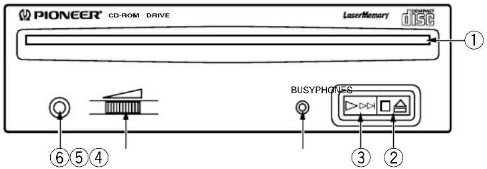
Front View
text_image
PIONEER® CD-ROM DRIVE LaserMemory DISC ① ⑥ ⑤ ④ BUSYPHONES ③ ②Fig.1
①Disc loading slot
Insert the CD-ROM with the label facing up.
PRECAUTIONS ON PLAYING CD SINGLES (8 cm Discs):
- When playing CD singles (8 cm discs), always use the adapter for 8 cm discs. Before loading the disc into the CD-ROM drive unit, be sure to check that it is secured properly by the catches of the adapter. If discs have been inserted without the adapter by mistake, remove the disc immediately by pressing the eject button. If the disc does not come out with one press, press another time.
- Use 8 cm disc adapters labeled with the DISC COMMACT DISC digital audio mark (recommended standard product). Do not use adapters which cause the disc to idle, nor adapters which are bent or curved.
②Stop (■)/Eject (▲) button
This button is used to eject the disc. When this button is pressed once during playback of an audio disc, the playback will be stopped, and when it is pressed in stopped condition, the disc will be ejected.
③ Play (▶)/Skip (▶▶) button
This is used for direct playback of audio discs. When an audio disc is inserted and this button is pressed, play status will be reached, and when this button is pressed in play status, the playback will skip to the next track. Data discs will not be played back.
④BUSY indicator
This flashes during data access.
⑤Volume Control (headphone level)
This is used to adjust the volume level of the headphone jack.
⑥Headphone jack (PHONES)
This is a stereo minijack for headphones.
Rear View
The display is on the top panel.
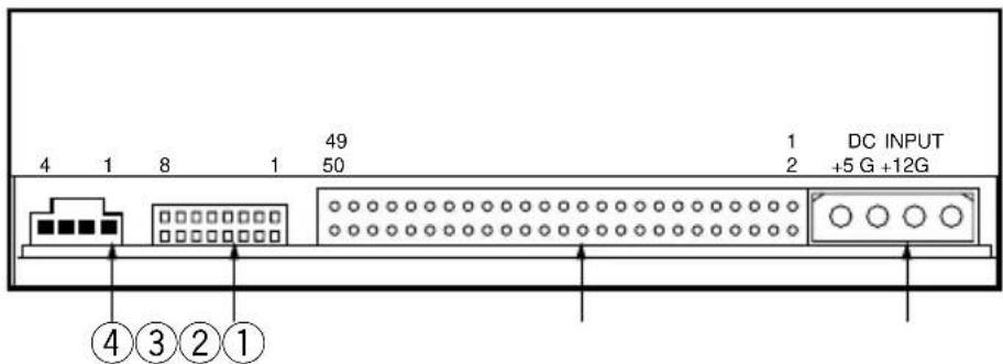
text_image
4 1 8 1 49 50 1 2 DC INPUT +5 G +12G ④③②①Fig.2
①DC Input
This is the input for DC +5 V and +12 V. Connect the computer power supply.
②SCSI interface
This is a 50-pin I/O connector according to the SCSI-2 specifications. Use a flat ribbon SCSI connector to connect to the SCSI host adapter.
③Function switch
Use the accessory short-circuit sockets to set the SCSI ID number and the drive function.
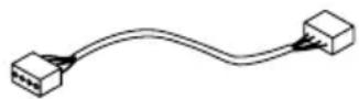
④Audio output
This is a connector for analog audio output. As a Molex 70553 is used, please select a suitable connection cable.
HARDWARE SETUP OVERVIEW
This chapter describes the steps required to connect your Pioneer Drive to your PC. Prior to installation, there are a few things you should know about this product.
First, the Drive is a SCSI device. What is a SCSI device? SCSI is an acronym for Small Computer System Interface. A SCSI system allows up to seven SCSI devices (including CD-ROM drives, hard disks, scanners, and tape drives) to be connected to each other in a series called a "daisy chain" A SCSI interface is the physical connection between a SCSI device and a computer serving as a pipeline to transfer data between the two.
♦ SCSI devices can be installed as an internal (inside your computer) device, as an external (outside your computer) device, or both. This unit is an internal drive. Once connected, signals are passed through the chain from one device to the next and order is kept by assigning a unique SCSI ID number to each device. The last device in a SCSI chain must be terminated to maintain the quality of the electrical signals in the cable.
Second (PCs only): Your System Must Have a SCSI Interface Card.
If your system dose not have a SCSI interface, you must buy and install one.
Third, Use the Proper Cable.
After installing a SCSI interface card or identifying the existing SCSI interface, it must be connected to your Drive using the proper cable.
A 50-pin flat ribbon cable is used to connect this unit to the computer.
Connection instructions are given on pages 16, 17.
SCSI COMPATIBILITY
If your interface card is not listed in the software installation menu, the card may still operate with your Drive. An ASPI* device driver is included with the Pioneer software which provides an interface between the Drive and a SCSI interface card. The ASPI driver translates the peculiarities of the interface card into a standard interface protocol thus establishing compatibility with the Drive. There is one requirement, the interface card must have a software device driver known as an ASPI Manager.
If you are uncertain whether your card came with an ASPI Manager, check the documentation for the card. If you find that the card didn't come with an ASPI Manager, contact the manufacturer or check with an Authorized Pioneer Dealer to see if a driver is now available.
INTERFACE CARD RECOMMENDATIONS
Pioneer drivers have been written to work with built-in SCSI port, on PCs with Future Domain SCSI Interface Cards, IBM SCSI Interface Cards, and ASPI compatible interface cards. Other SCSI interface cards require drivers provided by the manufacturer of the card.
INSTALLING A SCSI INTERFACE CARD IN A PC
SCSI interface card installation instructions accompany the card. For best results, follow the instructions that ship with the card.

Note: The SCSI interface card must be properly installed before continuing with the Drive installation.

SETTING THE SCSI ID
SCSI devices are identified by a SCSI ID number from 0 through 7 with ID number 7 typically reserved for the SCSI interface card. The basic rule for assigning a SCSI ID number requires that: Each SCSI device have a unique ID number (address) on the SCSI bus. If two SCSI devices are assigned the same ID number, your computer will not operate properly.
Assigning a SCSI ID to the Drive if you have a PC:
To avoid conflicts with an existing SCSI device and the interface card, choose an unassigned number in the range of 0-6.
Tip:

Make list of your SCSI devices and their assigned ID numbers to avoid a SCSI ID conflict.
Assigning a SCSI ID to the Drive:
- The three SCSI ID setting switches 0, 1, and 2 (#1, #2 and #3) compose a digital switch. Please execute setting according to the following table.
The jumper is ON when a short-circuit socket is inserted to short-circuit the upper and lower pin, and it is OFF in open condition.
* If the personal computer has no other built-in SCSI equipment except this unit, please use the unit with the factory setting (ID No. 2).
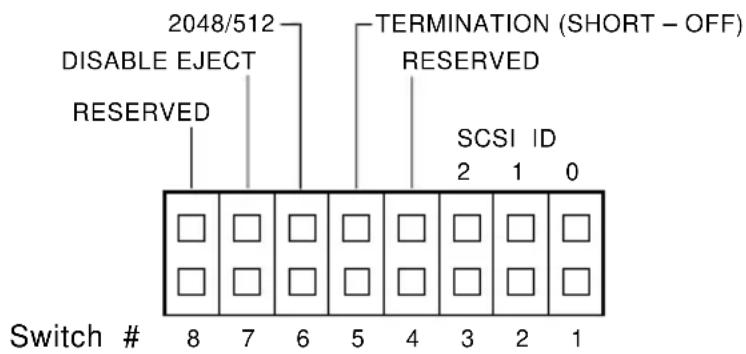
text_image
2048/512 DISABLE ELECT RESERVED TERMINATION (SHORT - OFF) RESERVED SCSI ID 2 1 0 Switch # 8 7 6 5 4 3 2 1OFF (open) ON (short-circuited) * The factory setting is for ID No. 2.
7

WARNING
DO NOT assign SCSI ID number 7 which is normally reserved for the SCSI interface.
SCSI TERMINATION
SCSI termination is a technique used to absorb line reflections at the beginning and end of a SCSI daisy chain that would otherwise interfere with legitimate SCSI signals and cause errors. To minimize interference with data transfer, SCSI termination is absolutely required for proper operation of your Drive.
WHEN TERMINATION IS REQUIRED
If you are installing the Drive as the only SCSI device or as the last SCSI device in the chain, termination must be enabled.
A built-in terminator switch is located on the rear panel. Function Switch #5 is used to enable or disable termination as described on page 14.
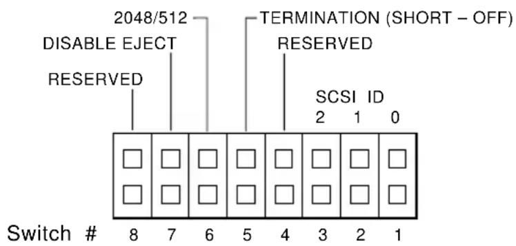
text_image
2048/512 DISABLE ELECT RESERVED TERMINATION (SHORT - OFF) RESERVED SCSI ID 2 1 0 Switch # 8 7 6 5 4 3 2 1As you can see in the above illustrations, whether you have an ON/OFF Terminator Switch or a Termination Function Switch, your Drive has an ON/OFF termination option.
ON: The Terminator Switch must be open when the drive is:
◆ the only SCSI device connected to an interface card; and/or
◆ the last physical device in a daisy-chain.
OFF: The Terminator Switch must be short-circuited when the drive is:
◆ connected in the middle of a SCSI chain.
SETTING FUNCTION SWITCHES
Function Switches, also known as Jumper Switches, control the operational functions of the CD-ROM Drive.
The jumper is ON when a short-circuit socket is inserted to short-circuit the upper and lower pin, and it is OFF in open condition.
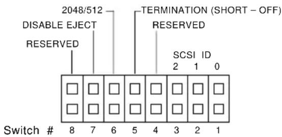
SWITCH SETTING TABLE
The display is on the top panel.
Switch 4 - Reserved
MUST BE SET TO OFF (OPEN)
Switch 5: SCSI Terminator
The built-in switch which enables or disables SCSI termination.
Short = SCSI Termination OFF : SCSI termination disabled (factory default setting).
Open = SCSI Termination ON: SCSI termination enabled.
Note: This information is described in detail earlier in this chapter under SCSI Termination on page 13.
Switch 6: Default Sector Size
Set the default sector size for the Drive when the drive is ON.
Short = 512-byte sector size (required for some UNIX systems)
Open = 2048-byte (2K) sector size (factory default setting)
For PC systems, the recommended setting is OFF (open). To confirm which sector size should be used in your system, refer to your system documentation.
Switch 7 - Disable Eject Button
Specifies if the power is ON to the front panel eject button.
Short = Disables the eject button.
Open = Enables the eject button (factory default setting).
Switch 8 - Reserved
MUST BE SET TO OFF (OPEN)
text_image
2048/512 DISABLE ELECT RESERVED TERMINATION (SHORT - OFF) RESERVED SCSI ID 2 1 0 Switch # 8 7 6 5 4 3 2 1
WARNING
The short-circuit switches always must be inserted vertically, never horizontally.
natural_image
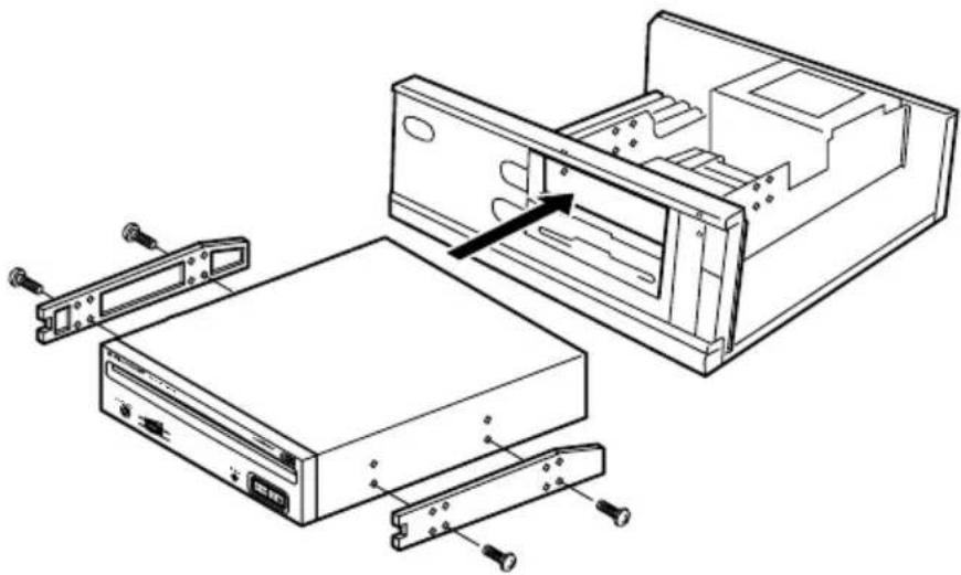
Technical line drawing of an open computer drive chassis with internal components and mounting hardware (no text or symbols)Fig.3
- Switch off the power of the personal computer and remove the cover or the front panel.
- Remove the blank panel installed at the front of the 5.25 inch slot. Installation is not possible when there is no empty slot.
- Install the fixation slide rails on the drive. (If slide rails are required, contact the shop where you bought the computer or the computer manufacturer.)
- Insert the drive into the slot.
- If fixing is required, fix the drive according to the instruction manual for the computer.

Use mounting screws with a length of 5 mm or less. Use of long screws may damage the drive.

Install the drive after the power supply of the personal computer has been switched off.

When the mounting screws are loose etc., the vibrations from disc rotation can generate a ripping noise, so that the screws should be tightened securely.

The drive installation method differs according to the computer type. For details, please refer to the manuals of your computer.
text_image
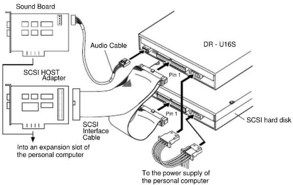
Sound Board Audio Cable SCSI HOST Adapter Dr - U16S Pin 1 SCSI Interface Cable Pin 1 SCSI hard disk Into an expansion slot of the personal computer To the power supply of the personal computerFig.4
When a SCSI hard disk or other SCSI equipment also is installed in the computer, please connect according to the following method.
●Switch off the power supply of the personal computer.
- Set the SCSI ID number so that it is different from the ID numbers of all other SCSI units.
- Set the termination OFF.
- Connect the power supply cable from the personal computer. At the time of connection, pay attention to the cable polarity. Please use a power supply cable with two or more connectors in parallel.
- Connect the SCSI interface cable. At this time, confirm that the pin 1 of the SCSI connector is connected correctly to pin 1 of the cable. Use a cable with two or more connectors in parallel.
- When a sound board is used, connect the audio output with an audio cable to the sound board.
text_image
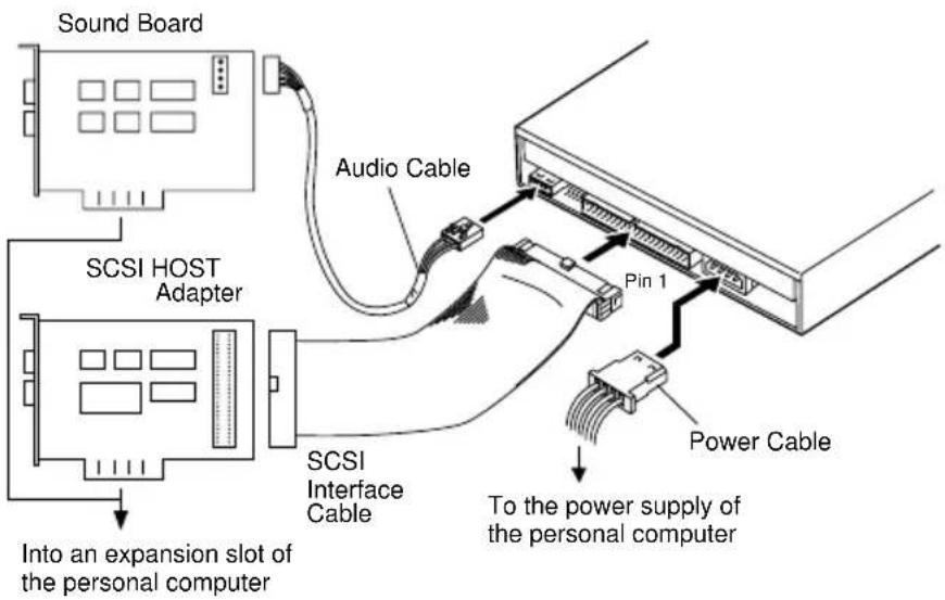
Sound Board SCSI HOST Adapter Audio Cable Pin 1 SCSI Interface Cable Power Cable To the power supply of the personal computer Into an expansion slot of the personal computerFig.5
When no SCSI hard disk or other SCSI equipment is used, connect according to the following connection method.
●Switch off the power supply of the personal computer.
- Set the SCSI ID number.
- Set the termination ON.
- Connect the power supply cable from the personal computer. At the time of connection, please pay attention to the cable polarity.
- Connect the SCSI interface cable. At this time, confirm that the pin 1 of the SCSI connector is connected correctly to pin 1 of the cable.
- When a sound board is used, connect the audio output with an audio cable to the sound board.

WARNING
The power supply of the personal computer always must be switched off before cables are connected.

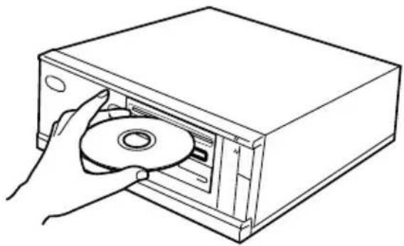
DISC SETTING METHOD
●Disc setting
Insert the disc into the disc loading slot with the label facing up.
When using 8 cm discs, attach a CD adapter (available at stores) to the disc, and insert the disc into the disc loading slot.
natural_image
Line drawing of a hand inserting a CD into a box (no text or symbols)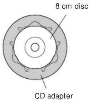
text_image
8 cm disc CD adapter
natural_image
Line drawing of a hand inserting a CD into a box (no text or symbols)Fig.6

Do not insert 8 cm discs by themselves.

When using a CD adapter, attach it properly to the disc, and check that it does not come off to prevent damage to the disc and adapter.

Do not attempt to insert more than two discs at one time, nor insert discs during play.

Do not insert the disc with excessive force so that it bends nor attempt to insert it by force. While the unit is pulling in or ejecting discs, do not attempt to do the opposite using force as this may cause damage to the disc or malfunction of the unit.
DISC REMOVAL METHOD
- Confirm that the BUSY indicator of the drive is not lit, and then press the Eject button (▲).
- Remove the disc after it has been ejected.

Do not place anything within 12 cm in front of the unit as this may obstruct the disc ejection operation of the unit.
CD-ROM DISC INFORMATION/FORMATS SUPPORTED
●High Sierra, CD-ROM XA, (Mode 2, Form 1 and 2), Rock Ridge and, CD-DA audio Discs.
MEDIA DIAMETER
- 120 mm/12 cm/4.72" disc and 80 mm/8 cm/3.15" disc (always attach adapters available at stores to 8 cm discs).
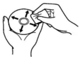
HANDLING OF CD-ROM DISCS
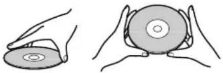
- When holding discs, DO NOT touch the data surfaces (the shiny side of the disc). Hold the disc by the edges or by one edge and the center hole.
natural_image
Illustration of two hands holding a CD or DVD disc, showing front and side views (no text or symbols)Disc Handling
- DO NOT affix labels or adhesive tape to either side of the discs. Also, DO NOT scratch or damage the label.

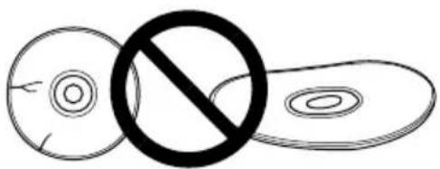
DO NOT use damaged, cracked, or warped discs. If they break inside the unit, they may damage the optics. Discs rotate at high speed inside the changing mechanism.
text_image
Diagram showing a crossed-out circle with a prohibition symbol, likely indicating a prohibition or exclusion in a biological or chemical context.
DO NOT use non-standard discs, as these may adversely influence this unit and other equipment.

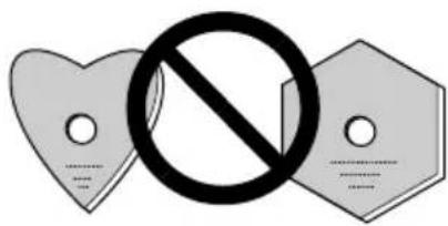
DO NOT play a CD having other shape than a circular disc, such as heart shaped disc. Otherwise malfunction may occur.
text_image
Symbolic image showing a prohibition sign crossed over two heart-shaped labels with placeholder text belowUSING THE AUDIO FEATURES
This unit has a function for playback of audio discs by itself. This is a function for audio playback without using computer software.
- Set an audio disc into the drive.
- When the Play/Skip button is pressed once, audio playback will be started from the beginning of the disc.
- When the Play/Skip button is pressed again, the playback skips to the beginning of the next track and playback is continued from there.
●To stop the playback of a disc, press the Stop/Eject button once. - When the Eject/Stop button is pressed twice, the disc will be ejected.
The audio output can be heard using the headphone jack or the audio output terminals.
USING THE HEADPHONE FEATURES
The volume knob controls the headphone volume level. When the knob is turned to the right, the headphone volume increases, and when it is turned to the left, the volume decreases.
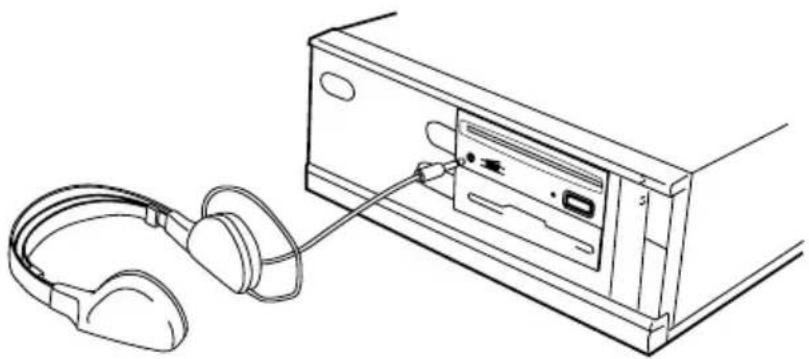
natural_image
Line drawing of an electronic device with headphones connected to a CD-ROM drive (no text or symbols)Fig.7
Incorrect operations are often mistaken for trouble and malfunctions. If you think that there is something wrong with this unit, check the points below according to the symptom.
If your computer did not start up correctly because the initial diagnostics did not recognize a SCSI device, check these items:
●Were all of your SCSI devices plugged in and turned on before you started your computer?
The Drive and all of the SCSI devices in the daisy chain must be turned on before you start your computer.
●Are your cables connected properly?
All cables must be attached to the correct ports.
●Are your SCSI IDs set properly?
Each device on a SCSI chain must have a unique SCSI ID.
●Have you set termination properly?
If the Drive is the only SCSI device, it must be terminated.
●Have you installed the software driver properly that came with your Drive?
If you have not installed the software device drivers yet, refer to the Installation instructions.
If data cannot be read from the CD-ROM disc:
- Is this disc properly inserted in the slot with the label side facing ↑ UP ?
●Is the BUSY indicator light on?
●Is the disc in proper operating condition?
●Is the SCSI cable connected correctly to the interface card and/or other SCSI devices?
●Are you sure there is a disc in the slot (drive) you are trying to access?
If music cannot be played back:
●Are you sure an audio CD is being used?
●Is the audio amplifier, powered speakers, or headphone set connected?
●Are you using CD-DA Audio?
Some audio formats require an audio sound card in the computer to decode digital Audio CD-DA.
●Are you operating the Drive that is not connected to a SCSI 2 interface card? Bringing digital audio from the CD-ROM disc into the computer requires a SCSI 2 interface card.
●Is the volume turned high enough?
Disc cannot be ejected:
●Has the Function Switch for the eject button been pushed to the ON disabled position? Function Switch #7.
If yes, move the switch to the OFF position.
PLACEMENT, CARE, AND CLEANING
CLEANING DISCS
- Fingerprints or smudges on the surface of the disc will not directly affect the recorded signals. However, data might not be read properly because of reduced brightness of the light reflected from the data surfaces. Clean discs by wiping them gently with a soft cloth from the inner edge toward the outer perimeter.
natural_image
Hand holding a circular object with directional arrows, no text or symbols presentDisc Cleaning
- If a disc becomes very dirty, wipe the dirt away gently with a soft, slightly damp, cloth. The disc must be completely dry before placing it on the disc tray.
●DO NOT use record cleaning sprays or antistatic agents on discs.
● DO NOT clean discs with benzene, thinner, or other volatile solvents.
[General functions]
Disc diameter 12 cm (4.72 in), 8 cm (3.15 in)
Transfer rate
Sustained 2,100 - 5,400 kBytes/sec*
* The data transfer rate may not be output for some disc conditions (scratches, etc.).
Seek time
Line 0.7 Vrms ± 0.1 Vrms (at 10 kΩ load)
[Others]
Power supply DC +12 V, 0.9 A (peak), 0.55 A (normal)
(With the built-in terminator) DC +5 V, 1.8 A (peak), 0.75 A (normal)
External dimensions 148 (W) x 42.3 (H) x 207.5 (D) mm
5-27/32 (W) x 1-11/16 (H) x 8-6/32 (D) in
Weight 0.97 kg (2.1 lb)
Operation temperature + 5°C to +45°C (41°F to 113°F)
Operation humidity 5% to 85% (no condensation)
Storage temperature - 40°C to +60°C (-40°F to 140°F)
Storage humidity 5% to 90% (no condensation)
[Accessories]
- Software device drive disk x 1
● Short-circuit socket x 4 - Audio cable x 1
- Mounting screw x 4
- Operating instructions x 1
● Installation instructions x 1
NOTE:
Specifications and design subject to possible modifications without notice, due to improvements.
text_image
CLASS 1 LASER PRODUCT LASER KLASSE 1natural_image
Technical line drawing of an open computer drive chassis with internal components and mounting hardware (no text or symbols)Fig.3
natural_image
Line drawing of a hand inserting a CD into a box (no text or symbols)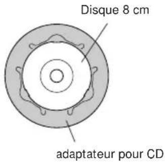
natural_image
Line drawing of a hand inserting a CD into a computer case (no text or symbols)Fig.6

natural_image
Illustration of two hands holding a circular disc, showing different angles (no text or symbols)natural_image
Simple line drawing of a circle with a diagonal slash and a horizontal line, no text or symbols present.
text_image
Image showing a prohibition symbol crossed over two heart-shaped labels, indicating no restrictions or violations.UTILISATION DES CARACTERISTIQUES AUDIO
natural_image
Line drawing of an electronic device with headphones connected to a CD-ROM drive (no text or symbols)Fig.7
35

natural_image
Hand holding a CD or DVD disc with arrows indicating rotation direction (no text or symbols)Nettoyage du disque
text_image
CLASS 1 LASER PRODUCT LASER KLASSE 1natural_image
Technical line drawing of an open computer drive chassis with internal components and mounting hardware (no text or symbols)Abb.3
natural_image
Line drawing of a hand inserting a CD into a box (no text or symbols)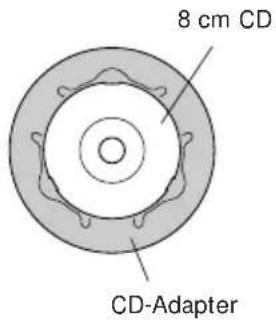
text_image
8 cm CD CD-Adapter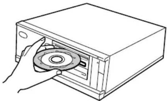
natural_image
Line drawing of a hand inserting a CD into a box (no text or symbols)Abb.6

natural_image
Illustration of two hands holding a circular disc, one open and one closed (no text or symbols)Halten einer CD-ROM
natural_image
Simple line drawing of a circle with a diagonal slash and an oval shape, no text or symbols present.
text_image
Prohibition symbol with three heart-shaped labels and a central prohibition signAUDIO-FUNKTIONEN
natural_image
Line drawing of an electronic device with headphones connected to a CD-ROM drive (no text or symbols)Abb.7
natural_image
Line drawing of hands holding a circular object with directional arrows indicating rotation (no text or symbols)text_image
CLASS 1 LASER PRODUCT LASER KLASSE 1| Impostazione commutatore | ID SCSI | |||||||
| 0 | 1 | 2 | 3 | 4 | 5 | 6 | 7 | |
| 0 (LSB) (#1) OFF ON | OFF | ON OFF | ON OFF | ON | ||||
| 1 (#2) OFF OFF ON | ON OFF | OFF | ON ON | |||||
| 2 (MSB) (#3) OFF OF | OFF OFF | OFF | ON ON | ON ON | ||||
natural_image
Technical line drawing of an open computer drive chassis with internal components and mounting hardware (no text or symbols)Fig.3
natural_image
Line drawing of a hand inserting a CD into a rectangular box (no text or symbols)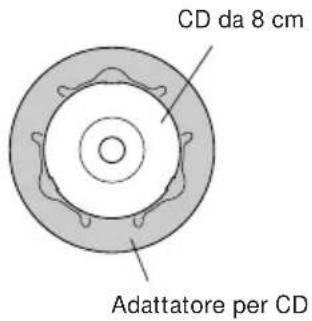
natural_image
Line drawing of a hand inserting a CD into a box (no text or symbols)Fig.6

natural_image
Illustration of two hands holding a CD or DVD disc, showing the front and side views (no text or symbols)natural_image
Simple line drawing of a circle with a diagonal slash and two concentric circles, no text or symbols present.
text_image
Image showing a prohibition symbol crossed over two heart-shaped labels, indicating no restrictions or violations.natural_image
Line drawing of an audio headset connected to a CD-ROM drive (no text or symbols)Fig.7

natural_image
Hand holding a circular object with directional arrows, no text or symbols presentPulizia del disco
AFTER-SALES SERVICE FOR PIONEER PRODUCTS
Please contact the dealer or distributor from where you purchased the product for its after-sales service (including warranty conditions) or any other information. In case the necessary information is not available, please contact the Pioneer's subsidiaries (regional service headquarters) listed below:
PLEASE DO NOT SHIP YOUR PRODUCT TO THE COMPANIES at the addresses listed below for repair without advance contact, for these companies are not repair locations.
AMERICA
PIONEER ELECTRONICS SERVICE, INC.
CUSTOMER SUPPORT DIVISION
P.O. BOX 1760, LONG BEACH, CA 90801-1760, U.S.A.
EUROPE
PIONEER ELECTRONIC (EUROPE) N.V.
EUROPEAN SERVICE DIVISION
HAVEN 1087, KEETBERGLAAN 1, 9120 MELSELE, BELGIUM
ASEAN
PIONEER ELECTRONICS ASIACENTRE PET. LTD.
SERVICE DEPARTMENT
501 ORCHARD ROAD, #10-00
WHEELOCK PLACE, SINGAPORE 238880
JAPAN AND OTHERS
PIONEER ELECTRONIC CORPORATION (HEAD OFFICE)
CUSTOMER SUPPORT CENTER
France : tapez 36 15 PIONEER
Published by Pioneer Electronic Corporation.
Copyright © 1998 Pioneer Electronic Corporation.
All rights reserved.
PIONEER ELECTRONIC CORPORATION
Business Systems Company, Overseas Sales Department: 4-1, Meguro 1-Chome, Meguro-ku, Tokyo 153-8654, Japan
PIONEER NEW MEDIA TECHNOLOGIES, INC.
Multimedia and Mass Storage Division: 2265 East 220th Street, Long Beach, CA 90810, U.S.A. TEL:800-444-OPTI (6784)
PIONEER ELECTRONICS SERVICE, INC. 1925 East Dominguez St. Long Beach, CA 90810, U.S.A. TEL: 310-952-2820
PIONEER ELECTRONIC [EUROPE] N.V.
Multimedia Division: PIONEER House, Hollybush Hill, Stoke Poges, Slough SL2 4QP, U.K. TEL: +44-1753-789-789
PIONEER ELECTRONICS OF CANADA, INC.
Industrial Products Department: 300 Allstate Parkway, Markham, Ontario L3R 0P2, Canada TEL: 905-479-4411
PIONEER ELECTRONICS AUSTRALIA PTY. LTD. 178-184 Boundary Road, Braeside, Victoria 3195, Australia TEL:+61-3-9586-6300
PIONEER ELECTRONICS ASIACENTRE PTE. LTD. 501 Orchard Road, #10-00, Lane Crawford Place, Singapore 0923 TEL: +65-735-9011