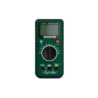
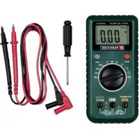
USER MANUAL PDM 300 C3 PARKSIDE
https://www.targa.gmbh/downloads/conformity/374242_2104.pdf
- Intended use 25
- Package contents 25
- Technical specifications 26
- Safety instructions 29
5.Copyright 33
6.Before you start 34
6.1 Inserting / replacing the battery 34
- Getting started 35
7.1 Out of range display 36
7.2 DC voltage measurement 36
7.3 AC voltage measurement 36
7.4 DC or AC current measurement 37
7.5 Function generator 37
7.6 Resistance measurement 38
7.7 Continuity testing 39
7.8 Diode test 39
7.9 HOLD function 40
7.10 Standing the multimeter up 40
- Maintenance/cleaning 40
8.1 Maintenance 40
8.2 Replacing the fuse 41
8.3 Cleaning 42
-
Environmental regulations and disposal information 43
-
Conformity notes 44
- Warranty and service information 45
Congratulations!
By purchasing the PARKSIDE PDM 300 C3 Digital Multimeter hereinafter referred to as the multimeter, you have opted for a quality product.
Before first using it, familiarise yourself with the way the multimeter works and read these operating instructions through carefully. Be careful to follow the safety instructions and only use the multimeter as described in the operating instructions and for the applications given.
Keep these operating instructions in a safe place. If you pass the multimeter on to someone else, make sure to give them all the relevant documents with it.
1. Intended use
The multimeter allows you to measure DC/AC voltages and direct and alternating currents. The multimeter also has functions for resistance measurement and diode testing, a function generator and a continuity check function. This multimeter has not been designed for corporate or commercial use. Use the multimeter for private purposes only. Any use other than that mentioned above does not correspond to the intended use. This multimeter fulfils all relevant norms and standards associated with CE Conformity. In the event of any modification to the multimeter that was not approved by the manufacturer, compliance with these standards is no longer guaranteed. The manufacturer shall not be liable for any damage or malfunctions resulting from such modifications.
Observe the regulations and laws in the country of use.
2. Package contents
- Multimeter
- 2 measuring probes (inc. cables)
- 9 V block battery
- 1 screwdriver
These operating instructions
These operating instructions have a fold-out cover. On the inside of the cover is a diagram of the multimeter with the components numbered. The meanings of the numbers are as follows:
1 Display
2 HOLD button (memory button)
3 Range selector switch
4 COM connection (earth
5 OUT INPUT connection ( = square wave signal)
6 Measuring probes (inc. cables)
7 10 A connection
8 SELECT button (switches between direct/alternating current)
3. Technical specifications
| Display 3 1/2 digit LC display, max. | display:
1999 |
| Measurement rate approx. 2 to 3 measurements/second |
| Measurement cable length approx. 80 cm each |
| Battery type 9 V block battery | |
| Overvoltage category CAT III 300 | V (digital multimeter and measurement cables) |
| Hold function yes | |
| Automatic polarity display yes | |
| Low battery display yes | |
| Auto power OFF function yes | |
| Operating temperature, humidity 0 | °C to +40 °C, max. 75 % RH |
| Storage temperature, humidity -10 | °C to +50 °C, max. 85 % RH |
| Dimensions (W x H x D) 80 x 166 | x 36.5 mm (inc. range selector switch) |
| Weight approx. 225 g (without battery or measurement cables) |
The technical data and design may be changed without prior notice.
DC voltage
| Range | Resolution | Precision |
| 200 mV 0.1 mV | | ± (0.5 % + 5) |
| 2 V 0.001 V | |
| 20 V 0.01 V | |
| 200 V 0.1 V | |
| 300 V 1 V | |
Input impedance: 10M
Overload protection: 300 V DC/AC RMS
AC voltage
| Range | Resolution | Precision |
| 2 V 0.001 V | | ± (1.0 % + 5) |
| 20 V 0.01 V | |
| 200 V 0.1 V | |
| 300 V 1 V | |
Input impedance: 10M
Frequency range: 40Hz to 400Hz
Overload protection: 300 V AC RMS
Display: Root mean square value (RMS of sine wave)
Direct Current
| Range | Resolution | Precision |
| 200 μA 0.1 μA | | ± (1.0 % + 5) |
| 2000 μA 1 μA | |
| 20 mA 0.01 mA | | ± (1.2 % + 5) |
| 200 mA 0.1 mA | |
| 2 A 0.001 A | | ± (2.0 % + 5) |
| 10 A 0.01 A | |
Overload protection: F1: F 250 mA / 300 V fuse
F2: F 10 A / 300 V fuse
Maximum input current: 10 A (input current >2 A for continuous measurement < 10 seconds and interval >15 min.)
Alternating current
| Range | Resolution | Precision |
| 200 μA 0.1 μA | | ± (1.2 % + 5) |
| 2000 μA 1 μA | |
| 20 mA 0.01 mA | | ± (1.5 % + 5) |
| 200 mA 0.1 mA | |
| 2 A 0.001 A | | ± (3.0 % + 7) |
| 10 A 0.01 A | |
Overload protection: F1: F 250 mA / 300 V fuse
F2: F 10 A / 300 V fuse
Maximum input current: 10 A (input current >2 A for continuous measurement < 10 seconds and interval >15 min.)
Frequency range: 40Hz to 400Hz
Display: Root mean square value (RMS of sine wave)
Resistor
| Range | Resolution | Precision |
| 200 Ω 0.1 Ω | | ± (1.0 % + 5) |
| 2 kΩ 0.001 kΩ | |
| 20 kΩ 0.01 kΩ | |
| 200 kΩ 0.1 kΩ | |
| 2 MΩ 0.001 MΩ | | ± (1.2 % + 5) |
| 20 MΩ 0.01 MΩ | |
Overload protection: 300 V
Function generator
| Signal | Voltage | Output |
| 1 kHz square wave signal | approx. 3 V peak-peak | approx. 10 kOhm |
The precision quoted in ± (\% of display + number of digits) applies for 5% to 100% of the relevant measurement range and is guaranteed for a period of one year at an ambient temperature of 18^ to 28^ and a max. air humidity of 75% . If the conditions are different, the precision is not guaranteed.
4. Safety instructions
Before you use this multimeter for the first time, please read the following notes and heed all warnings, even if you are familiar with handling electronic devices. Keep these operating instructions in a safe place for future reference. If you sell the multimeter or pass it on, always include these instructions.

WARNING! This signal word indicates a danger with a moderate risk, which can lead to death or major injuries if not avoided.

CAUTION! This signal word indicates important instructions to protect against damage to property.

This symbol denotes further information on the topic.

DANGER! Before opening the multimeter, it must be isolated or disconnected from dangerous active voltage. There is a risk of electric shock!

DANGER! This symbol denotes harmful electric voltage!

AC voltage
DC voltage

Function generator (square wave signal)

Continuity testing

Diode test

Protection Class II

WARNING! Electrical devices are not suitable for children. People with disabilities should only use electrical devices within the limits of their abilities. Never allow children or persons with disabilities to use electrical devices unsupervised. They may not comprehend the potential risks. Batteries and small parts represent potential choking hazards. Therefore, keep the battery in a safe place. If a battery is swallowed, seek medical help immediately. Keep the packaging out of the reach of these people. Packaging material is no toy. There is a risk of suffocation!

WARNING! Do not short-circuit the battery. Remove the battery from the device when you are not going to use it for a long period of time. If the battery has leaked, remove it to prevent damage to the device. You can wipe off any leaked battery fluid by using a dry, absorbing cloth. Always wear protective gloves! Avoid any skin contact. If the battery fluid comes into contact with the skin or eyes, rinse immediately with plenty of water and seek medical aid.

WARNING! Non-rechargeable batteries must not be recharged.

WARNING! Do not short-circuit any battery contacts.

WARNING! Batteries must be inserted respecting the correct polarity.

WARNING! When it is empty, remove the battery from the device and dispose of safely.

WARNING! If you notice any smoke, unusual noises or strange smells, stop the measurement immediately. If this occurs, the multimeter should not be used before it has been inspected by authorised service personnel. Never inhale smoke from a possible device fire. If you do inadvertently inhale smoke, seek medical attention. Smoke inhalation can be damaging to your health.

WARNING! Always hold the measuring probes by the handle area (see diagram). The area with the warning sign must not be touched, otherwise there is a risk of electric shock while measuring!


WARNING! Do not use the multimeter if it or the measuring probes (inc. cables) are damaged. There is a risk of electric shock!

WARNING! Be especially careful when dealing with AC voltages over 30 V or DC voltages over 60 V. There is a risk of electric shock!

WARNING! Never operate the multimeter with the housing open. There is a risk of electric shock!

WARNING! Do not touch the contacts of the measuring probes or the connectors during the measurement, otherwise there is a risk of electric shock.

WARNING! Do not use the multimeter in damp or wet environments. Also make sure that your hands and shoes are dry, otherwise there is the risk of electric shock!

WARNING! Do not use the multimeter near explosive gases or vapours or in dusty environments. There is risk of explosion!

WARNING! Make sure that no fire hazards (e.g. burning candles) are placed on or near the multimeter. Fire hazard!

CAUTION! Never exceed the maximum input values quoted. Otherwise the multimeter could get damaged.

CAUTION! Do not exceed the overvoltage category CAT III quoted. Otherwise the multimeter could get damaged.
CAT III: Measurements within building installations (e.g. distribution boxes, cabling, sockets and switches). This category also includes the following two categories:
CAT II: Measurements on electrical and electronic devices supplied with power via a mains plug.
CAT I: Measurements on electrical circuits with no direct connection to the mains (battery-powered, car electrics, etc.).

CAUTION! Before changing the measurement range, disconnect the multimeter from the object it is measuring, otherwise it could get damaged.

CAUTION! When using the measurement probes, connect the black measurement cable to the COM connection first, then connect the red one. When disconnecting, remove the red measurement probe first.

CAUTION! Never connect a voltage source to the measurement probes if it is set to continuity testing, resistance measurement, diode test, function generator or current measurement. Otherwise the multimeter could get damaged.

CAUTION! Do not expose the multimeter to any direct heat sources (e.g. heaters), direct sunlight or strong artificial light. The device must not be exposed to spray or dripping water or abrasive liquids. Do not use the multimeter near water. The multimeter must especially never be immersed (do not place any containers containing liquids such as drinks, vases, etc. on the multimeter). Make sure that the multimeter is not subject to excessive shocks or vibrations. Do not introduce any foreign bodies into the device. Otherwise the multimeter could get damaged.
5. Copyright
All the contents of this user manual are protected by copyright and provided to the reader for information only. Copying data and information without the prior explicit written consent of the author is strictly forbidden. This also applies to any commercial use of the contents and information. All texts and diagrams are up-to-date as of the date of printing.
6. Before you start
Remove the multimeter and the accessories from the packaging. Before first use, remove the protective film from the display [1].
Check the multimeter and the accessories for damage. If the multimeter is damaged, do not use it.
6.1 Inserting / replacing the battery
The multimeter is powered by a 9 V block battery. The procedure for inserting or replacing the battery is as follows:

WARNING! Switch the multimeter off and remove all measurement cables before opening it!

CAUTION! If the battery is empty, the + symbol appears on the display [1]. The battery should be replaced as soon as possible to ensure proper functioning.
- Use the screwdriver provided to undo the top screw on the back of the multimeter and remove the battery compartment cover by pulling it upwards.

- Connect the 9 V block battery to the battery clip with the correct polarity (note + and -) and insert it into the battery compartment.

- Replace the battery compartment cover and retighten the screw you undid before.
7. Getting started

CAUTION! Never exceed the max. input values stated.
Switch the multimeter on by twisting the range selector switch [3] to your chosen measurement range. The multimeter has an auto power OFF function which works as follows:
- If the multimeter is not used for approx. 15 minutes, a beep sounds. Another minute later, another beep sounds and the device switches into sleep mode. Press any button to stop it doing so.
- To wake the multimeter up out of sleep mode, turn the range selector switch [3] to a different measurement range or press any button.
- In order to deactivate the auto power OFF function, proceed as follows: When you switch on the multimeter, press and hold the SELECT button [8]. The symbol for the auto power OFF function is no longer shown on the display [1].
- Next time you switch the multimeter on, the auto power OFF function is active again and the display [1] shows the symbol again.
You can also switch the multimeter off directly by turning the range selector switch [3] to the "OFF" position.
7.1 Out of range display
The multimeter has an out-of-range display. If a measured value exceeds the range limit for the measurement range selected, "0L" is shown on the display [1]. If this happens, remove the measurement probes [6] from the object you are measuring immediately.
7.2 DC voltage measurement
- Connect the black measurement cable to the COM connection [4] and the red measurement cable to the OUT INPUT connection [5].
- Set the range selector switch [3] to the V-position.
- Connect the measurement probes [6] to the object to be measured.
- The measured reading is now shown on the display [1]. If the measured reading is negative, a minus sign is shown in front. If "OL" is flashing on the display [1], AC voltage is being measured. Set the range selector switch [3] to the V~ position.
7.3 AC voltage measurement
- Connect the black measurement cable to the COM connection [4] and the red measurement cable to the OUT INPUT connection [5].
- Set the range selector switch [3] to the V~ position.
- Connect the measurement probes [6] to the object to be measured.
- The measured reading is now shown on the display [1].
7.4 DC or AC current measurement
- Connect the black measurement cable to the COM connection [4] and the red measurement cable to the 10 A connection [7] (for currents >200mA ) or the OUT INPUT connection [5] (for currents <200mA ).
- Select the range selector switch [3] to the current measurement range you want (μA, mA or A). If you do not know the current level, set it first to the highest measurement range and then switch down to the lower ranges until you have a satisfactory reading.
- Press the SELECT button [8] to switch between direct and alternating current. The relevant symbol is shown on the display [1].
- Connect the measurement probes [6] in series to the object to be measured.
- The measured reading is now shown on the display [1]. If the measured reading is negative, a minus sign is shown in front for DC current measurements.
7.5 Function generator

CAUTION! Make sure that all circuit components, circuits and parts to be measured are disconnected and discharged. Otherwise the multimeter could get damaged.
- Connect the black measurement cable to the COM connection [4] and the red measurement cable to the OUT INPUT connection [5].
- Set the range selector switch [3] to the position.
- Connect the measurement probes [6] to the object to be measured.

The 1 kHz square wave signal is used, among other things, for checking and repairs on headphones, amplifiers and other electronic devices and components.
7.6 Resistance measurement

CAUTION! Make sure that all circuit components, circuits and parts to be measured are disconnected and discharged. Otherwise the multimeter could get damaged.
- Connect the black measurement cable to the COM connection [4] and the red measurement cable to the OUT INPUT connection [5].
- Set the range selector switch [3] to the position.
- Connect the measurement probes [6] to the object to be measured.
- The measured reading is now shown on the display [1]. If the display [1] shows "OL", the measuring probes [6] make no contact with the resistance to be measured or the resistance is faulty.

For resistances >1M , the measurement may take a few seconds. In this case, wait until the reading has stabilised.

For measurements of lower resistances (200 Ω range), the resistance of the device's own measurement cables can distort the reading. In order to avoid this, note down the reading for the measurement with the measurement probes short-circuited, and subtract this from the actual measurement reading.
7.7 Continuity testing

CAUTION! Make sure that all circuit components, circuits and parts to be measured are disconnected and discharged. Otherwise the multimeter could get damaged.
- Connect the black measurement cable to the COM connection [4] and the red measurement cable to the OUT INPUT connection [5].
- Set the range selector switch [3] to the position.
- Connect the measurement probes [6] to the object to be measured.
- If the resistance is under about 30 , the buzzer sounds and the measured reading is shown on the display [1].
7.8 Diode test

CAUTION! Make sure that all circuit components, circuits and parts to be measured are disconnected and discharged. Otherwise the multimeter could get damaged.
- Connect the black measurement cable to the COM connection [4] and the red measurement cable to the OUT INPUT connection [5].
- Set the range selector switch [3] to the position.
- Connect the red measurement probe [6] to the anode of the diode to be tested and the black measurement probe [6] to the cathode.
- The threshold voltage is shown in volts on the display [1]. If the display [1] shows "OL", the diode is being measured in the wrong direction or it is faulty. Carry out a measurement in the opposite direction to check.
7.9 HOLD function
Pressing the HOLD button [2] allows a measured reading to be saved on the display [1]. Press the HOLD button [2] again to revert back to measurement mode. While the Hold function is enabled, the icon will show on the display.
7.10 Standing the multimeter up
You can stand the multimeter up. To stand the multimeter up, fold out the stand on the back.

8. Maintenance/cleaning
8.1 Maintenance

WARNING! Maintenance is required if the multimeter has been damaged in any way, for example, if liquid has entered the product, if the multimeter has been exposed to rain or moisture, if the multimeter is not working properly or if it has been dropped. If this occurs, the multimeter should not be used before it has been inspected by authorised service personnel. All servicing work must be carried out by qualified specialist personnel.
8.2 Replacing the fuse
Proceed as follows: to replace the fuse:

WARNING! Switch the multimeter off and remove all measurement cables before opening it!
- Use the screwdriver provided to undo the top screw on the back of the multimeter and remove the battery compartment cover by pulling it upwards.

- Undo the four screws on the back of the multimeter and remove the back panel.

- Replace the spent F1 (F 250 mA / 300V) or F2 (F 10 A / 300 V) fuse with a new one of the same type.
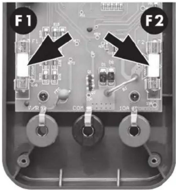
- Replace the back panel and retighten the four screws you undid before. Then, secure the battery compartment cover again using the screw.
8.3 Cleaning

WARNING! Switch the multimeter off and remove all measurement cables before cleaning it!
To clean use a dry cloth. Never use any solvents or cleaners that may damage the plastic materials. Make sure that no liquid gets into the housing. For more stubborn dirt, use a slightly damp cloth.

Devices marked with this symbol are subject to the European Directive 2012/19/EU. All electrical and electronic devices must be disposed of separately from household waste at official disposal centres. Proper disposal of old devices prevents damage to the environment or your health. For further information about proper disposal, contact your local council, recycling centre or the shop where you bought the device.

Respect the environment. Old batteries must not be disposed of with domestic waste. They must be handed in at a collection point for waste batteries. Please note that batteries must be disposed of fully discharged at appropriate collection points for old batteries. If disposing of batteries which are not fully discharged, take precautions to prevent short circuits.

Dispose of all packaging in an environmentally friendly manner. Cardboard packaging can be taken to paper recycling centres or public collection points for recycling. Any film or plastic contained in the packaging should be taken to your public collection points for disposal.

Only relevant for France:
The product can be recycled, is subject to an extended producer responsibility and is collected separately.

Please note the markings on the packaging material when disposing of it, it is labelled with abbreviations (a) and numbers (b), the meanings of which are as follows: 1-7: plastic / 20-22: paper and cardboard / 80-98: composite materials.

The outer and inner packaging are made of corrugated cardboard and can be recycled into further packaging.

The display protection film is made of PVC (polyvinyl chloride).
Disposal
When it reaches the end of its service life, for the sake of the environment, do not dispose of the product in the household waste, but dispose of it properly. Your local council can provide information on collection points and their opening times. Faulty or spent batteries must be recycled in accordance with Regulation 2006/66/EC and any amendments to it. Always take spent batteries/battery packs or the product to the corresponding collection points.
Environmental damage through incorrect disposal of batteries!
Do not dispose of any batteries with domestic waste. They can contain toxic heavy metals and must be handled as specialist waste. The chemical symbols of the heavy metals are as follows: Cd = Cadmium, Hg = Mercury, Pb = Lead. Always take spent batteries to a local collection point.
CE
The product complies with the requirements of the applicable European and national directives. Evidence of conformity has been provided. The manufacturer has the relevant declarations and documentation.
A U K CA
The product complies with the requirements of the applicable national directives of the Republic of Serbia.
The product complies with the requirements of the applicable national directives for Great Britain.
The complete EU Declaration of Conformity is available for download from this link:
https://www.targa.gmbh/downloads/conformity/374242_2104.pdf
Warranty of TARGA GmbH
This device is sold with three years warranty from the date of purchase. Please keep the original receipt in a safe place as proof of purchase. Before using your product for the first time, please read the enclosed documentation. Should any problems arise which cannot be solved in this way, please call our hotline. Please have the article number and, if available, the serial number to hand for all enquiries. If it is not possible to solve the problem on the phone, our hotline support staff will initiate further servicing procedures depending on the fault. Within the warranty period the product will be repaired or replaced free of charge as we deem appropriate. No new warranty period commences if the product is repaired or replaced. Consumables such as batteries, rechargeable batteries and lamps are not covered by the warranty.
Your statutory rights towards the seller are not affected or restricted by this warranty.

Service

Phone: 0800 404 7657
E-Mail: targa@lidl.co.uk

Phone: 1890 930 034
E-Mail: targa@lidl.ie

Phone: 800
62230
E-Mail: targa@lidl.com.mt

Phone: 8009
4409
E-Mail:
targa@lidl.com.cy
IAN:374242_2104

Manufacturer
TARGA GmbH
Coesterweg 45
59494 Soest
GERMANY
Table des matieres
https://www.targa.gmbh/downloads/conformity/374242_2104.pdf
https://www.targa.gmbh/downloads/conformity/374242_2104.pdf
Resolver (firkantbølgesignal)

Kontinuitetstest

Diodetest

Beskyttelsesklasse II