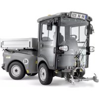
B 300 R I LPG - Industrial sweeper Kärcher - Free user manual and instructions
Find the device manual for free B 300 R I LPG Kärcher in PDF.

| Product type | Combined industrial sweeper (wet cleaning and sweeping) |
| Brand | Kärcher |
| Model | B 300 R I LPG |
| Dimensions (L x W x H) | 2490 x 1570 x 1860 mm |
| Empty weight | 1775 kg |
| Maximum permissible weight | 2635 kg |
| Engine | Kubota WG1605-L-E3 (LPG), 4 cylinders, 36 kW / 48 HP at 2550 rpm |
| Fuel | LPG (propane/butane, propane content ≥ 90%), 11 kg bottle |
| Clean water tank capacity | 271 liters |
| Dirty water tank capacity | 270 liters |
| Dust hopper capacity | 180 liters |
| Working width (without side accessory) | 1045 mm |
| Working width (with side accessory) | 1350 mm (1400 mm with side broom) |
| Max. working speed | 10.7 km/h |
| Max. speed (forward) | 12 km/h |
| Max. speed (reverse) | 5 km/h |
| Max. gradient (direction of travel) | 12% |
| Turning radius | 3150 mm |
| Battery | 12 V, 80 Ah |
| Sound pressure level (LpA) | 87 dB(A) |
| Sound power level (LWA) | 104 dB(A) |
| Safety | Parking brake, seat safety contact, rollover protection, emergency stop |
| Maintenance | Daily emptying of dust hopper, filter cleaning, level checks, lubrication |
| Accessories | Brushes, side brooms, suction lips, filters, loading ramp |
Frequently Asked Questions - B 300 R I LPG Kärcher
User questions about B 300 R I LPG Kärcher
0 question about this device. Answer the ones you know or ask your own.
Ask a new question about this device
Download the instructions for your Industrial sweeper in PDF format for free! Find your manual B 300 R I LPG - Kärcher and take your electronic device back in hand. On this page are published all the documents necessary for the use of your device. B 300 R I LPG by Kärcher.
USER MANUAL B 300 R I LPG Kärcher
natural_image
Exterior view of a Kärcher industrial cleaning robot with visible snowflakes and control panel (no text or symbols on the robot itself)Deutsch 2
English 42
Français 81
Italiano 120
Nederlands 160
Español 199
Português 238
Ελληνικά 277
text_image
Labeled interior view of a vehicle's steering wheel and dashboard with numbered parts for identification1 Fahrersitz
2 Bremspedal
3 Fahrpedal
4 Funktionsschalter
5 Lenkrad
text_image
Industrial machine control panel with numbered labels pointing to various safety symbols and warning signsnatural_image
Close-up of a car's front grille and side bumper with a coiled collar attachment (no text or symbols visible)natural_image
Interior view of a vehicle engine bay with visible hoses, valves, and structural components (no text or symbols)1 Verschlussdeckel
text_image
Industrial machine control panel with warning labels and warning symbols, showing a hand operating a tooltext_image
Labeled interior view of a mechanical or electronic device with numbered components and visible wiringGEFAHR
Unfallgefahr!
text_image
Labeled interior view of a vehicle's steering wheel and dashboard with numbered parts, showing control buttons and adjustment knobs.natural_image
Close-up of an orange gas cylinder with a yellow connector inserted, mounted on a black base (no visible text or symbols)6.1.5 Motor starten
ACHTUNG
natural_image
Interior view of a mechanical device with numbered annotations pointing to components (no readable text or symbols)text_image
Labeled diagram of a mechanical device with numbered components and control panel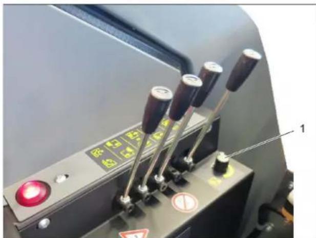
natural_image
Industrial control panel with three vertical sliders and a red indicator light, no visible text or symbolsACHTUNG
text_image
Labeled diagram of a cleaning or cleaning machine with numbered componentstext_image
Labeled diagram of a mechanical device with numbered components and control buttonsACHTUNG
text_image
Labeled diagram of a robotic device with numbered components and an inset showing internal components with warning symbols.natural_image
Close-up of a cleaning or cleaning machine component with labeled parts (1 and 2), no readable text or symbols beyond labels.1 Seitenbesendeck
2 B o l z e n
natural_image
Industrial cleaning machine with labeled components (no visible text or symbols)natural_image
Close-up of a car's front grille and side-mounted tire, showing a small circular component attached to the wheel (no text or symbols visible)⚠ VORSICHT
text_image
Labeled diagram of an electronic device showing numbered components including battery, wires, and housing.ACHTUNG
text_image
Close-up of a car engine with numbered parts labeled 1 and 2, showing internal components like fuel tanks, motors, and suspension systems.1 Ölmessstab
2 Öleinfülldeckel
text_image
Industrial machinery diagram with numbered components and labeled parts, likely for industrial equipment or equipment identification.⚠️WARNUNG
Verbrennungsgefahr!
text_image
Labeled mechanical assembly diagram showing components numbered 1, 2, and 3 with arrows indicating movement or connection points.text_image
Labeled mechanical assembly diagram showing components numbered 1 to 3, likely for industrial inspection or testing.text_image
Close-up of automotive engine components with numbered labels pointing to parts 1 and 2natural_image
Interior view of a vehicle engine bay with hoses and components (no visible text or symbols)1 Deckel
natural_image
Close-up of a robotic car wheel with attached sensor and sensor components, labeled 'A' (no text or symbols on the vehicle itself)
natural_image
Close-up of a mechanical assembly with labeled component 'B' and wiring (no readable text or symbols beyond label)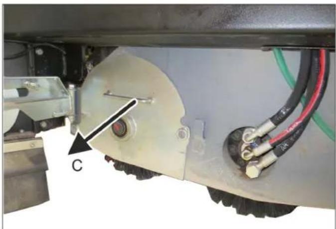
natural_image
Close-up of a mechanical assembly with visible components and wiring (no text or symbols)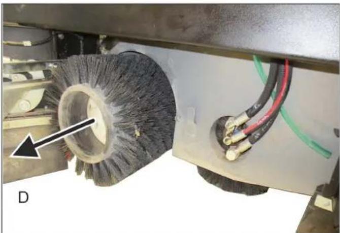
natural_image
Close-up of a cleaning brush head with visible brush and wiring, no text or symbols presentnatural_image
Close-up of a mechanical gear assembly with labeled parts (1 and 2), no readable text or symbols beyond labels1 Seitenbesen
2 Schrauben
text_image
Labeled diagram of a mechanical device showing components 1, 2, and 3 with orange warning lighttext_image
Labeled diagram of a mechanical device showing components 1, 2, and 3 with visible wiring and components.text_image
Labeled diagram of a cleaning or cleaning machine with numbered componentsnatural_image
Interior view of a mechanical assembly with numbered components (1, 2, 3), no visible text or symbols on the main structure.text_image
Technical diagram of a robotic vehicle with labeled parts including wheel, guide, and sensors1 Saugbalken
2 Saugschlauch
3 Dichtleiste
text_image
Labeled diagram of a robotic device showing components 1, 2, and 3 with visible wiring and mounting hardware.natural_image
Close-up of a heat exchanger or cooling unit with visible cooling pipes and heat sinks (no text or symbols)⚠️ WARNING
text_image
X173.1 X173.1 1 2 3 4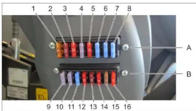
text_image
1 2 3 4 5 6 7 8 A B 9 10 11 12 13 14 15 16Chairman of the Board of Management

S. Reiser
Director Regulatory Affairs & Certification
71364 Winnenden (Germany)
Tel.: +49 7195 14-0
Fax: +49 7195 14-2212
Winnenden, 2022/02/01
1 Contents
1 Contents EN 1
2 Information about the vehicle EN 2
2.1 Proper use EN 2
2.2 General notes EN 3
3 Safety instructions EN 4
3.1 Notes on unloading/unpacking EN 4
3.2 General notes on safety EN 4
3.3 Work clothing EN 4
3.4 Safety instructions concerning the operation EN 4
3.5 Safety information concerning the driving operation EN 4
3.6 Safety guidelines for LPG vehicles (only gas engine) EN 4
3.7 Safety information concerning the combustion engine EN 6
3.8 Safety information concerning the transport of the vehicle EN 6
3.9 Safety information concerning maintenance and care EN 6
3.10 Safety Devices EN 6
4 Overview of the appliance EN 7
4.1 Operating elements EN 8
4.2 Warning / control display EN 8
4.3 Control lever EN 9
4.4 Function switch EN 9
5 Start up EN 9
5.1 Unpack the device and unload it EN 9
5.2 Pushing/towing the device (without engaging self-propulsion) EN 10
5.3 General notes EN 10
5.4 Install/replace gas bottle EN 11
5.5 Daily before starting operations EN 12
5.6 Adjusting driver's seat EN 12
5.7 Set the steering wheel position EN 13
5.8 Filling the tank (diesel motor) EN 13
6 Operation EN 13
6.1 Drive mode EN 14
6.2 Wet cleaning EN 15
6.3 Sweep EN 18
6.4 Turn off device EN 20
7 Transport EN 20
7.1 Loading the vehicle for transport EN 20
7.2 Towing the vehicle EN 21
8 Storage/decommissioning EN 21
9 Care and maintenance EN 22
9.1 General notes EN 22
9.2 Cowlings EN 22
9.3 Battery EN 22
9.4 Maintenance intervals EN 23
9.5 Inspection and maintenance work EN 24
9.6 Replacing brushes EN 28
9.7 Replacing side brushes EN 29
9.8 Cleaning EN 29
9.9 Replacement tasks EN 33
9.10 Accessories EN 34
10 Troubleshooting EN 34
10.1 Faults with display EN 34
10.2 Faults without display EN 35
11 Specifications EN 37
12 EU Declaration of Conformity EN 39
13 Declaration of Conformity EN 39

Please read and comply with these original operating instructions prior to the initial operation of your vehicle and store them for later use or subsequent owners.

The terms device, vehicle and machine are used synonymously in these operating instructions.
2 Information about the vehicle
Immediately inform your dealer or sales facility if you detect any defects or transport damage upon the delivery of the vehicle.
Warning and information plates on the machine provide important directions for safe operation.
2.1 Proper use
The B 300 RI is a combination device for wet cleaning and sweeping without refitting.
This appliance is suited for the commercial use, e.g. in hotels, schools, hospitals, factories, shops, offices, and rental companies.
Depending on the cleaning tasks, different brushes may be used and a selection can be made between side brushes deck and side scrubbing deck.
These operating instructions describe the maximum attachments in addition to the motor variants of diesel and gas. Your device may differ from these.
With adequate ventilation, the gas version (LPG) can be used in inside areas (halls and industrial buildings).
Carefully read the operating instructions and familiarise yourself with the control devices and the remaining equipment prior to using the vehicle.
The vehicle must only be used as intended, as outlined and described in these operating instructions.
The intended use also includes the observance of the required maintenance.
The vehicle and the attachments may only be used, maintained and repaired by persons that are familiar with the tasks and have been briefed about the associated risks.
The general safety and accident prevention regulations of the legislator must be observed. Other applicable safety-relevant, occupational health and road traffic regulations must be observed.
The operating personnel must:
– be physically and mentally capable
– be trained in handling the vehicle
– read and understand the operating instructions prior to starting work
– have demonstrated the entrepreneur the skills for driving the vehicle
– are appointed to drive the vehicle by the entrepreneur. The vehicle must meet the applicable national directives when operated on public roads.
The machine is only suitable for use on the types of surfaces specified in the operating instructions.
2.1.1 Suitable floors for cleaning as a wet cleaning device
■ Industrial floor
■ Screed
Concrete
2.1.2 Suitable floorings for cleaning as a sweeper vacuum
Asphalt
■ Industrial floor
■ Screed
Concrete
■ Paving stones
In addition to the information contained in the operating instructions, all statutory safety and accident prevention regulations must be observed.
2.1.3 Function
- Wet cleaning
The appliance is used for the wet cleaning of level floors. It can be easily adjusted to the cleaning task by setting a cleaning program and the water quantity. The side scrubbing deck conveys the waste into the middle where it is taken up by the counter-rotating brushes.
A suction blower generates vacuum pressure and suctions the detergent solution into the waste water tank.
- Sweep
If the device is to be used mainly for sweeping, then the installation of a special roller brush and conversion to a side brushes deck are to be recommended.
Note: Have the conversion to the side brushes deck carried out by Kärcher Customer Service, because parameters in the control must be changed.
The side brushes deck transport the waste into the middle. The two counter-rotating brushes convey the waste into the waste container. A suction blower prevents dust from escaping.
If the waste container is full, then it can be emptied hydraulically from the driver seat.
2.1.4 Foreseeable misuse
Any use other than the one intended and described above is prohibited. The user is liable for any hazards arising from incorrect use.
The use for any other purposes than described in these instructions is prohibited.
Transporting persons on the device is not permitted.
The appliance may not be modified.
Do not use the device at elevations of over 2000 m.
- Never vacuum up explosive liquids, combustible gases or undiluted acids and solvents. This includes petrol, paint thinner or heating oil which can generate explosive fumes or mixtures upon contact with the suction air. Acetone, undiluted acids and solvents must also be avoided as they can harm the materials on the machine.
- Never sweep/vacuum up reactive metal dusts (e.g. aluminium, magnesium, zinc), as they form explosive gases when they come in contact with highly alkaline or acidic detergents.
- Do not sweep/vacuum up any burning or glowing objects.
- The machine may not be used or stored in hazardous areas. It is not allowed to use the appliance in hazardous locations.
– It is prohibited to drive with the waste container (hopper) raised. - Do not use the appliance without an overhead guard in areas where the operator might get hit by falling objects.
- Do not clean without installed brushes, sealing lips or suction lips.
2.2 General notes
2.2.1 Accessories and Spare Parts
Only use original accessories and spare parts, they ensure the safe and trouble-free operation of the device.
For information about accessories and spare parts, please visit www.kaercher.com.
To avoid risks, all repairs and replacement of spare parts may only be carried out by the authorised customer service personnel.
2.2.2 Environmental protection, REACH and disposal of the worn out vehicle
2.2.2.1 Environmental protection

The packaging material can be recycled. Please do not throw the packaging material into household waste; please send it for recycling.
Batteries, oil, fuels and similar substances must not be released into the environment. Please dispose of these substances via suitable collection systems.
2.2.2.2 Ingredients (REACH)
The latest information on ingredients can be found under: www.kaercher.de/REACH
2.2.2.3 Disposal of the worn out vehicle
Worn out vehicles contain valuable recyclable materials that should be recycled properly. We recommend to cooperate with a waste management company for the disposal of your vehicle.
2.2.3 Warranty
The warranty terms published by our competent sales company are applicable in each country. We will repair failures of your vehicle free of charge within the warranty period, provided that such failure is caused by faulty material or defects in fabrication. Please contact your Kärcher dealer or a Kärcher sales facility for this purpose.
2.2.4 Symbols in the operating instructions △DANGER
Warns about immediate danger which can lead to severe injuries or death.
⚠ WARNING
Warns about possible danger which could lead to severe injuries or death.
△CAUTION
Points out a possibly dangerous situation which can lead to light injuries or property damage.
ATTENTION
Pointer to a possibly dangerous situation, which can lead to property damage.
2.2.5 Symbols on the vehicle
 | Wear hearing protection. |
 | Always use appropriate gloves while working on the device. |
 | Risk of getting squeezed on account of getting jammed between vehicle parts. |
 | Risk of injury on account of moving parts. Do not reach in. |
 | Risk of burns on account of hot surfaces! Allow the exhaust to cool down sufficiently before starting work on the machine. |
 | Risk of fire. Do not vacuum up any burning or glowing objects. |
 | Risk of poisoning! Do not breathe in the exhaust fumes. |
 | The falling and rising gradients in the direction of travel may not exceed 12%. |
 | Maximum decline of ground when driving with the waste container raised. |
 | Lashing point |
 | Location points for the jack / axle stands |
3 Safety instructions
3.1 Notes on unloading/unpacking
⚠️ DANGER
Risk of injury, risk of damage!
→ The vehicle is not approved for crane loading.
→ Do not use a forklift to unload/load the appliance.
→ The packaging material (plastic bag, thermocol, etc.) is a potential source of danger and should not reach the hands of children.
→ Carefully unpack the device while refraining from using any tool that could damage the device. After unpacking, check whether the device is complete and fully functional. If not, call customer service.
3.2 General notes on safety
- The vehicle and its working equipment must be checked to ensure that it is in proper working order and operating safely prior to use. Otherwise, the appliance must not be used.
- If the vehicle is used in hazardous areas (e.g. filling stations), the corresponding safety instructions must be observed. It is not allowed to use the appliance in hazardous locations.
- To secure the device against an accidental start, turn the key switch to position "0" and remove the key.
- The ignition key of the vehicle may be made available only to trained operating, cleaning or maintenance staff.
3.3 Work clothing
- Always use appropriate gloves while working on the vehicle.
- Ensure that the operator wears tight-fitting clothes, wear safety shoes.
- Wear suitable headgear so that braids or long hair cannot get caught in rotating parts.
- Do not wear jewellery, rings or the like during work.
3.4 Safety instructions concerning the operation
- The operator must use the vehicle as intended. The local conditions must be considered and the operator must watch out for third parties, especially children, during work.
- Never leave the vehicle unattended as long as the motor is running. The operator may only leave the vehicle when the motor has been switched off and the vehicle is secured against accidental movements. If necessary, operate the parking brake and remove the ignition key.
- Close the gas valves each time after operation.
- The vehicle may only be used by persons who have been instructed in handling the vehicle or have proven qualification and expertise in operating the vehicle and have been explicitly assigned the task of handling it.
- The vehicle may not be operated by children or uninstructed persons.
- This machine is not intended for use by persons (including children) with reduced physical, sensory or mental capabilities, or lack of experience and knowledge.
– Children should be supervised to ensure that they are not playing with the vehicle. - Do not open the bonnet or the side panels while the motor is running.
3.5 Safety information concerning the driving operation
⚠️DANGER
Danger of tipping!
→ The falling and rising gradients in the direction of travel may not exceed 12%.
→ Drive slowly when cornering.
→ Danger of tipping on unstable ground.
→ Danger of tipping with excessive sideways tilt.
→ Danger of slipping on wet floors.
- It is important to follow all safety instructions, rules and regulations applicable for driving motor vehicles.
- The vehicle must not be operated by children or teenagers.
- In order to prevent unauthorised use of the vehicle, the ignition key must be removed.
– Prior to each use, the safety check described in the Chapter "Startup" must be conducted. - All operating levers and switches must be in neutral prior to starting the motor. The driver must be seated when the motor is started. The drive pedal must not be pressed during the starting process.
- The vehicle may only be started while sitting in the seat.
- Do not clean without installed brushes, sealing lips or suction lips.
- In the event of malfunctions in the brake system, turn off the vehicle and contact Customer Service.
3.6 Safety guidelines for LPG vehicles (only gas engine)
Hauptverband der gewerblichen Berufsgenossenschaften e.V. (HVBG / Germany). Liquefied gases (propellants) are butane and propane or a mixture of butane/propane. They are available in special cylinders. The operating pressure of these gases depends on the outside temperature.
△DANGER
Risk of explosion!
Do not handle liquified gas like petrol. Petrol evaporates slowly, liquified gas immediately turns into gas. The risk of gas spreading in the room and getting ignited is thus higher with liquid gas than with petrol.
CAUTION
Only use LPG cylinders filled with propellant gas in accordance with DIN 51622 quality.
The use of household gas and camping gas is strictly prohibited.
Liquid gas mixtures can be different for different gas motors. The approved liquid gas mixtures can be found in the technical data.
3.6.1 Liabilities of the factory management and the employee
- All persons handling liquid gases are liable to acquaint themselves with the special properties of the liquid gases for hazard-free handling of operations. The current documentation is always to be kept on hand.
3.6.2 Maintenance by expert
- Propellant-operated units are to be checked at regular intervals, at least once a year, by an expert against leaks (according to BGG 936) and ensure that the unit is functioning properly.
- The inspection must be certified and documented. The inspection guidelines are § 33 and § 37 UVV (occupation accident prevention regulations) "Use of liquid gas" (BGV D34).
– General applicable regulations are the guidelines for inspecting vehicles whose engines are driven by liquefied gases of the Federal Transportation Minister.
3.6.3 Commissioning/Operations
- Gas must always be drawn only from one cylinder. Drawing gas from multiple cylinders simultaneously can cause liquid gas from one cylinder flowing into the other. This causes the over-filled cylinder to be subjected to an unpermitted excess pressure when the cylinder valve is closed later (refer B.1 of these guidelines).
- Ensure the correct positioning of the cylinder with the "bottom" marking while connecting a full cylinder (the connection screw points vertically downward).
Perform the replacement of the gas cylinder carefully. During assembly and disassembly, the gas outlet nozzle of the cylinder valve must be sealed by means of a cap nut that is tightened using a wrench.
- Discontinue the use of leaky gas cylinders. Such cylinders are to be emptied by slowly letting out the gas in open spaces by conforming to all safety regulations and are to be indicated as leaky. Also inform the issuing company or its representative (the filling-station attendant) in writing about the damage to the cylinder while delivering or receiving the cylinders.
- Before connecting the gas cylinder, check that its connection neck is in a proper state.
- After connecting the cylinder, regularly check that it is not leaky by using a foaming agent.
- Open the valves slowly. Do not use hammers to open and close the cylinders.
- Use only dry fire extinguishers (with carbonic acid gas) in case of fire caused by liquefied gases.
- The entire LPG unit must be continuously checked to ensure that there are no leaks and the unit is functioning properly. Using the vehicle with a leaky gas unit is strictly prohibited.
- First close the cylinder valve before loosening the pipe or tube connection. Unscrew and loosen the connection nut of the gas cylinder slowly because otherwise the gas under pressure in the tube will flow out instantly.
- If the gas is refilled from a larger tank, then ask the sales agent of the LPG about the important regulations to be followed.
⚠️DANGER
Risk of injury!
– LPG in a liquid state can cause frost bites on bare skin.
- After disconnecting the cylinder, tighten the closing nut firmly on the connecting threading of the cylinder.
- Use soap water or some such foaming agent to check whether the cylinder is leaking. The use of open flames to illuminate the LPG unit is strictly prohibited.
- Follow the manufacturer's installation specifications while changing individual parts of the LPG unit. Close all cylinder and locking valves while doing so.
- Regularly check the status of the electrical unit of the LPG vehicles. Sparks can cause explosions if the gas-carrying parts of the unit are leaky.
- If a LPG-driven vehicle has been idling for a long time, then first ventilate the setting room before commissioning the vehicle or its electrical unit.
- Immediately inform the trade association and the concerned trade supervisory authority about accidents with gas cylinders or LPG units. Store the damaged parts carefully until all investigations have been completed.
3.6.4 In the installation and storage rooms as well as the workshops
- Propellants or LPG cylinders must always be stored according to the regulations of TRF 1996 (Technical Regulations for Liquid Gases, refer DA to BGV D34, Appendix 4).
- Always store the gas cylinders in a vertical position. Use of open flames and smoking at the installation site of the cylinders and during repairs is strictly prohibited. Protect the stored cylinders against unauthorised access. Close all empty cylinders properly.
- Close the cylinder and main locking valves immediately when you switch off the vehicle.
– Follow the regulations for garages and the construction guidelines of the respective State about the location and structure of the parking areas for LPG-driven vehicles.
– Gas cylinders are to be stored in separate rooms away from the parking areas (refer DA to BGV D34, Appendix 2).
- The electrical hand-held lamps used in the rooms are to be equipped with closed, sealed case and a strong protection cover.
- Close all cylinder and main valves before working in repair workshops and protect the gas cylinders against effect of external heat.
- A responsible person must check that all valves, especially the cylinder valves, are closed during operational breaks and before closing the factory. Do not carry out any jobs involving fire - such as cutting and welding jobs - in the vicinity of the gas cylinders. Do not store gas cylinders, not even empty ones, in the workshops.
- The parking and storage rooms and the repair workshops must be ventilated properly. Please note that liquefied gases are heavier than atmospheric air. They get collected on the floor, in recesses and other holes in the floors and form a gas-air mixture that can lead to explosions.
3.7 Safety information concerning the combustion engine
→ Read the operating instructions of the engine manufacturer before start-up and follow the safety instructions carefully.
⚠️DANGER
Risk of fire and explosion!
→ Only use the fuels specified in the operating instructions. Risk of explosion due to the use of inappropriate fuels. Refer to Chapter "Technical data".
→ When refuelling, ensure that no fuel reaches hot surfaces.
⚠️DANGER
Risk of poisoning!
→ B 300 RI LPG (gas engine)
Operating a vehicle indoors is allowed only if there is sufficient ventilation and if the expulsion of exhaust gases is possible.
→ B 300 RI D (Diesel engine)
Operating a vehicle indoors is prohibited.
→ Exhaust gases are poisonous and hazardous to health, do not inhale them.
⚠️DANGER
Risk of injury!
→ The exhaust gas opening of the combustion engine must not be closed.
→ The motor requires approx. 3 seconds to come to a standstill once it has been switched off. During this time, stay well clear of the drive area.
→ Risk of injury due to unprotected fan wheel.
DANGER
Risk of burns!
→ Do not touch hot combustion engine.
→ Allow the vehicle to cool down before removing the panels.
→ Do not bend over the exhaust or touch it.
⚠️DANGER
Scalding danger!
→ Never open the lid on the cooler while the motor has operating temperature. The container is under pressure.
3.8 Safety information concerning the transport of the vehicle
→ The motor must be shut down and the vehicle must be securely fastened on the lashing points during transport.
Refer to Chapter "Transport".
3.9 Safety information concerning maintenance and care
- Switch off the vehicle and, if necessary, remove the ignition key prior to performing any cleaning or maintenance tasks on the vehicle, replacing parts or switching over to another function.
- Maintenance work may only be carried out by approved customer service outlets or experts in this field who are familiar with the respective safety regulations.
- Observe the safety inspection pursuant to the applicable local provisions for mobile vehicles used for commercial purposes.
- Radiator fins, hydraulic hoses and valves, seals and electric and electronic components must not be cleaned with the high-pressure cleaner.
3.10 Safety Devices
⚠️DANGER
Safety installations serve the protection of the user and may not be modified or bypassed.
This vehicle is equipped with various safety systems.
- Parking brake
- Seat contact switch on the driver seat.
4 Overview of the appliance

text_image
KARCHER 1 2 3 4 5 6 7 8 9 10 11 12 13 14 15 16 17 18 19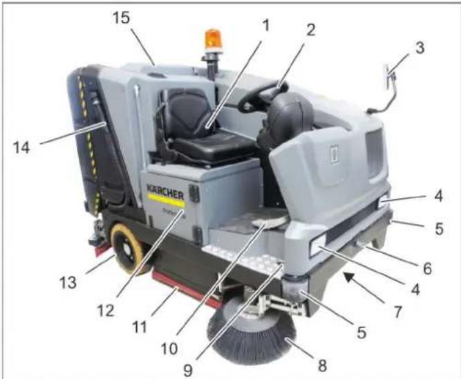
text_image
1 2 3 4 5 6 7 8 9 10 11 12 13 14 15 KARCHER1 Left motor cover
2 Engine bonnet
3 Fresh water tank
4 Electronics cover
5 Beacon lamp
6 Panels
7 Lift/tilt emptying mechanism
8 Suction blower, sweeping
9 Dust filter, sweeping
10 Deflector
11 Rollers
12 Waste container (not visible from outside)
13 Vacuum bar
14 Deflector
15 Wiping flap
16 Rear wheel
17 Sealing strip wet cleaning
18 Drainage hose for fresh water
1 Driver seat
2 Steering wheel
3 Rear-view mirror
4 Head lamp
5 Deflector
6 Towing eye
7 Front-wheel drive
8 Side brushes deck
9 Transport lock, side brushes deck
10 Drive pedal
11 Sealing strip wet cleaning
12 Gas version: Compartment for battery and gas bottle
Diesel version: Compartment for battery and fuel tank
13 Rear wheel
14 Dirt water discharge hose
15 Cover, flat fold filter and suction blower for wet vacuum cleaning
4.1 Operating elements
text_image
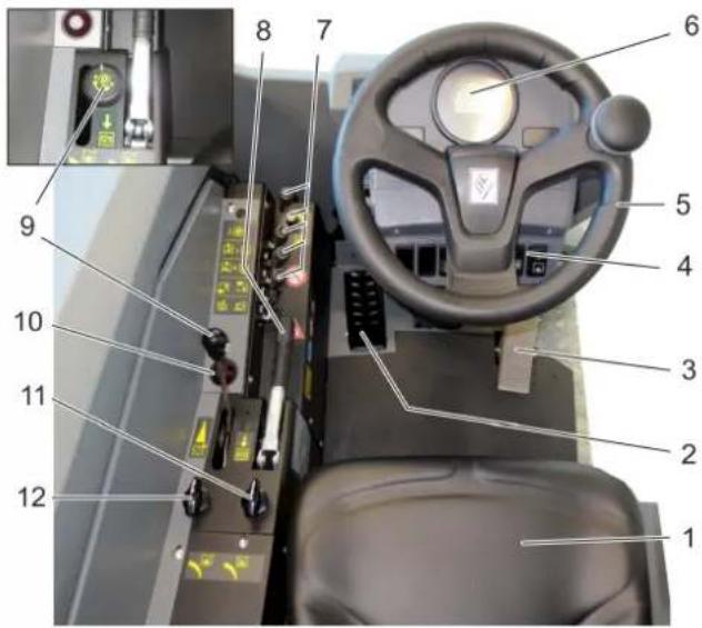
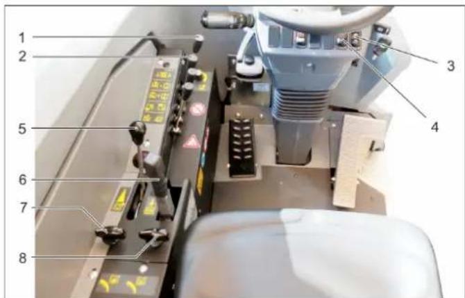
Labeled interior view of a vehicle's steering wheel and dashboard with numbered parts for identification1 Driver seat
2 Brake pedal
3 Drive pedal
4 Function switch
5 Steering wheel
6 Warning / control display
7 Control lever
8 Parking brake
9 Engine speed lever (Diesel versions) Engine speed potentiometer (gas versions)*
10 Display lamp (waste container flap)
11 Water dispensing, side scrubbing deck
12 Water dispensing, roller brush
Note
All control elements will be described in detail later on.
4.2 Warning / control display
text_image
9 10 11 12 8 7 6 5 4 3 8:00' 8:00' 8:00' 8:00' 13 14 15 16 17 18 2 1 22 21 20 19Note
All warning and control lights will light up briefly when the ignition is switched on, this is for testing the display lamps.
1 Warning lamp fuel reserve minimum (Diesel engine)
2 Indicator light Emptying waste container
3 Indicator light blinker, left
4 Warning lamp Motor trouble
5 Warning lamp engine temperature
6 Fuel tank level (diesel engine only)
7 Indicator light Vacuum turbine on
8 Indicator light Preglow (diesel engine only)
9 Warning light motor oil pressure
10 Position light (only with road homologation)
11 Indicator lamp for dipper
12 Warning lamp for battery charge indicator
13 Cooling water temperature of the motor
14 Warning lamp problems of alternator/engine
15 Indicator lamp for parking brakes
16 Warning light sweeping mode
17 Indicator light blinker, right
18 Indicator light dirt water tank maximum level
19 Motor rpm
20 Indication light fresh water tank minimum level
21 Operating hour counter
22 Indication light gas bottle minimum level (gas engine only)
4.3 Control lever
text_image
Industrial control panel with numbered labels pointing to various safety symbols and warning signs1 Brush contact pressure
2 Lever for steering wheel adjustment
3 Switching brushes on/off
4 Raising/lowering side brushes deck
5 Raising/lowering high emptying of waste container
6 Open/close flap of the waste container
4.4 Function switch
text_image
1 2 3 4 5 6 7 8 91 Steering wheel
2 Multifunctional lever for lights, indicators and horn
3 Not assigned
4 Not assigned
5 Filter cleaning for dust filter
6 Not assigned
7 Not assigned
8 Water pump switch
9 Switch for cleaning type: sweeping or scrubbing
Front position: Scrubbing cleaning type, the suction bar lowers and the suction turbine switches on.
Rear position: Sweeping cleaning type, the sweeping blower switches on. The suction bar remains up.
Central position: Switched off
5 S t a r t u p
5.1 Unpack the device and unload it
⚠️DANGER
Risk of injury, risk of damage!
→ The vehicle is not approved for crane loading.
→ Do not use a forklift to unload/load the appliance.
→ The packaging material (plastic bag, thermocol, etc.) is a potential source of danger and should not reach the hands of children.
→ Carefully unpack the device while refraining from using any tool that could damage the device. After unpacking, check whether the device is complete and fully functional. If not, call customer service.
→ Note information regarding pushing/towing the device in a later chapter.
→ Mind the vehicle weight during loading!
Net weight (transport weight) 1750 kg
5.2 Pushing/towing the device (without engaging self-propulsion)
text_image
close open 1 2The freewheel (bypass) of the hydraulic pump must first be opened before the device can be pushed/towed.
⚠️DANGER
Risk of injury!
→ Secure the device against rolling away prior to opening the freewheel.
Note
The travel drive is inoperable. Braking effect exists no more.
△CAUTION
Risk of damage to the hydrostatic axle drive!
→ Do not move the device for long distances without engaging self-propulsion; a speed of 5 km/h should not be exceeded.
1 Hydraulic pump
2 Screw for freewheeling (bypass)
→ Open engine cover.
Open freewheel (bypass)
→ Open the screw for the freewheel by at least 1/2 revolution (anti-clockwise).
Close freewheel (bypass)
→ After moving/towing the device, turn the screw for the freewheel back until it stops (clockwise).
natural_image
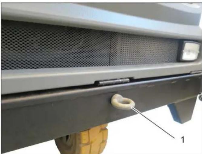
Close-up of a car's front grille and side-mounted sensors, showing mesh and tire details (no text or symbols visible)1 Towing eye
→ To tow the vehicle, attach the towing eye to the device at the front.
5.3 General notes
→ Read the operating instructions of the engine manufacturer before start-up and follow the safety instructions carefully.
→ Park the machine on an even surface.
→ Remove ignition key.
→ Lock parking brake.
5.4 Install/replace gas bottle
text_image
KARCHER Professional 1 2 3 4 5 6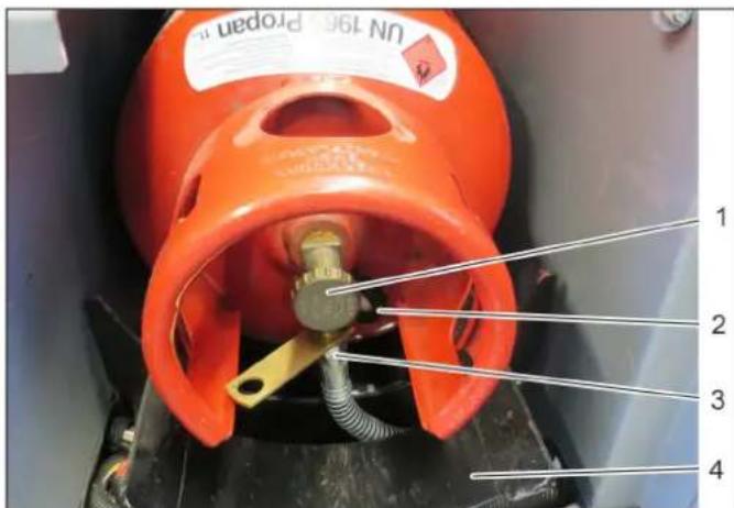
text_image
UN 196 Program II 1 2 3 4DANGER
Risk of injury!
→ Follow safety regulations for LPG vehicles.
→ Formation of crusts and yellow-frothing deposits on the gas cylinder indicate leakiness.
→ Cylinders must be changed only by instructed persons.
→ Cylinders containing propellant gases must not be changed in garages and underground areas.
→ Do not smoke and use uncovered light while changing the cylinder.
→ While changing cylinders, first close the locking valve of the LPG cylinder firmly and immediately put the protective cap on the empty cylinder.
⚠ WARNING
Only use replacement cylinders with 11 kg contents of tested models.
CAUTION
The use of household gas and camping gas is strictly prohibited.
LPG mixtures of propane and butane are permitted. The propane content must be at least 90%.
ATTENTION
Do not open the gas drawing valve until before starting the device (refer to chapter "Operation | Driving").
Open the gas drawing valve by turning it in anti-clockwise direction.
Gas bottle empty - replace gas bottle.
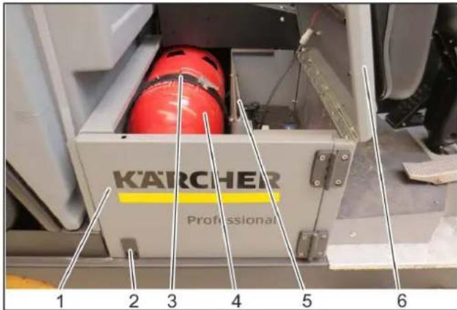
1 Panels
2 L o c k
To open, press downward
3 Bracket closure
4 Gas cylinder
5 Support
6 Cover with driver seat
→ Tilt the cover upwards and secure it with the support.
→ Open the lock and swivel the cladding outwards.
→ Close gas drawing valve by turning it in clock-wise direction.
→ Unscrew the gas hose (30-mm spanner).
→ Screw the protective cap onto the connecting valve of the empty gas cylinder.
→ Open the cliplock.
→ Remove the empty gas bottle.
Replace the gas cylinder.
1 Gas withdrawal valve
2 Protective cover
3 Gas hose with union joint
4 Gas bottle holder
→ Place the gas bottle in the retainer.
Note
Observe the installation position of the gas cylinder. The connection / ring opening must point downwards.
→ Close the bracket closure.
→ Unscrew the protective cap from the connecting valve of the gas cylinder.
→ Screw the gas hose to the connecting valve of the gas cylinder (30-mm spanner).
5.5 Daily before starting operations
→ Check fill level of fuel tank.
→ Check engine oil level.
→ Check the cooling water level on the expansion tank.
→ Check the hydraulic oil level.
→ Clean / replace the air filter of the internal combustion engine
→ Empty waste container.
→ Empty the waste water tank.
→ Fill fresh water tank as needed.
→ Check brushes for wear and damage.
→ Check suction lip of the suction bar for wear and damage.
→ Check/clean the water and suction system.
→ Check function of all operator control elements.
→ Check appliance for damages.
→ Clean the dust filter with the filter cleaning button.
Note: For description, see section on Care and maintenance.
5.5.1 Frost protection
natural_image
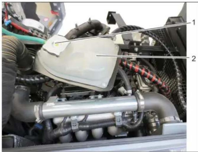
Interior view of a vehicle engine bay with visible hoses, springs, and components (no text or symbols)1 Closing head
2 Coolant expansion tank
→ If frost is expected, check whether there is enough anti-frosting agent in the cooling water.
→ Diesel motor
Below exterior temperatures of 6^ C, only Winter diesel must be used, as there might be problems with operating due to the flocking of diesel components.
5.6 Adjusting driver's seat
text_image
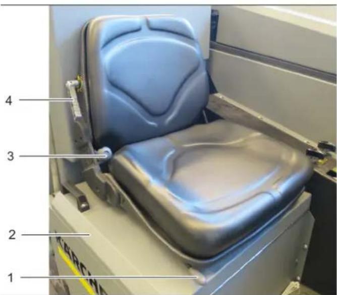
1 2 3 4△DANGER
Risk of accident!
→ Do not adjust the driver seat while driving.
1 Seat adjustment longitudinal direction
2 Cover with driver seat
3 Inclination adjustment back rest
4 Absorption / adjustment for driver's weight
5.7 Set the steering wheel position
text_image
15.8 Filling the tank (diesel motor)

text_image
Labeled interior view of a mechanical device with numbered components and visible wiringDANGER
Risk of accident!
→ Do not adjust the steering wheel position while driving.
1 Lever, steering wheel inclination adjustment
→ Open the steering wheel adjustment lever.
→ Adjust the steering wheel to the desired position.
→ Close the steering wheel adjustment lever.
DANGER
Risk of explosion!
→ Do not refuel the machine in enclosed spaces.
→ Smoking and open flames must be strictly avoided.
→ Ensure that no fuel reaches the hot open surfaces.
1 Cover with driver seat
2 Support
3 Tank lid
4 Fuel tank
→ Switch off engine.
→ Tilt the cover upwards and secure it with the support.
→ Open fuel filler cap.
→ Fill in diesel.
→ Insert the fuelling gun as deep as possible into the fuel nozzle. Do not add any more fuel once the fuelling gun stops according to the settings.
→ Wipe off any spilt fuel and close fuel filler cap.
5.8.1 Fuelling using a can
- Estimate the fuel requirement in order to avoid overflows.
6 Operation
DANGER
Risk of burns, risk of crushing!
→ Only use the vehicle if all panels are attached.
⚠ WARNING
Risk of damage due to overheated hydraulic oil or overheated motor!
→ In case of excessive hydraulic oil temperature or excessive cooling water temperature, set the motor speed to idling (do not switch off the motor) and perform the measures described in Chapter "Faults".
Risk of damage due to missing lubrication!
→ If the warning light for the oil pressure lights up during operation, immediately switch off the motor and rectify the fault.
⚠️DANGER
Long hours of using the appliance can cause circulation problems in the hands on account of vibrations.
It is not possible to specify a generally valid operation time, since this depends on several factors:
– Proneness to blood circulation deficiencies (cold, numb fingers).
- Low ambient temperature. Wear warm gloves to protect hands.
- A firm grip impedes blood circulation.
- Continuous operation is worse than an operation interrupted by pauses.
In case of regular, long-term operation of the device and in case of repeated occurrence of the symptoms (e.g. cold, numb fingers) please consult a physician.
6.1 Drive mode
text_image
Labeled diagram of a vehicle dashboard with numbered parts and control buttons1 Driver seat
2 Brake pedal
3 Drive pedal
4 Function switch
5 Steering wheel
6 Warning / control display
7 Control lever
8 Parking brake
9 Engine speed lever (Diesel versions)
Engine speed potentiometer (gas versions)*
10 Display lamp (waste container flap)
11 Water dispensing, side scrubbing deck
12 Water dispensing, roller brush
6.1.1 Drive pedal
The accelerator pedal can be used to drive forwards and backwards.
If the accelerator pedal is released, the hydrostatic drive of the vehicle is delayed or stopped.
6.1.2 Parking brake
The parking brake acts on the rear wheels and uses a sheathed cable. If the braking power starts to decline, it can be readjusted on the lever with a setting screw. The brake shoes should be replaced only by Customer Service.
6.1.3 Brake pedal
The brake pedal activates the brake system of the rear wheels. The correct setting of the brakes takes place automatically, no adjustment work is required.
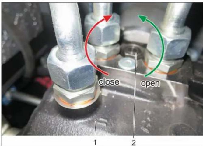
6.1.4 Opening the gas supply (gas engine)
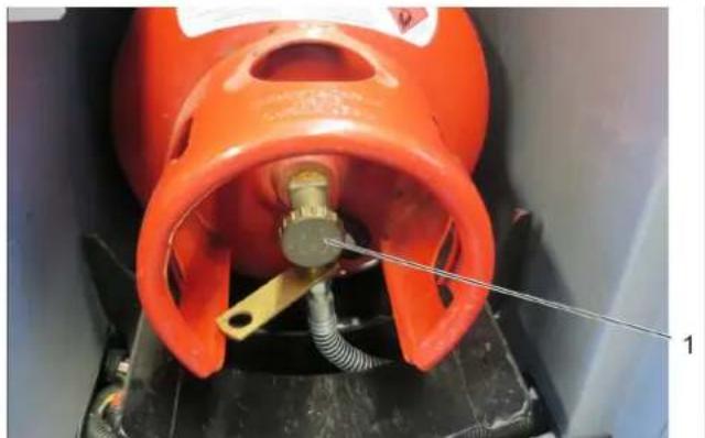
natural_image
Close-up of an orange gas cylinder with a yellow connector inserted, mounted on a black base (no visible text or symbols)ATTENTION
Always press the accelerator pedal carefully and slowly. Do not jerkily change from reverse to forward drive or vice versa.
ATTENTION
Check the braking effect of the parking brake now and then; the braking effect is OK if the vehicle can be stopped on an incline of 16^ .
Actuation takes place hydraulically, therefore always make sure that there is a sufficient amount of brake fluid in the storage tank.
1 Gas withdrawal valve
→ Open the gas drawing valve by turning it in anti-clockwise direction.
6.1.5 Start the engine
ATTENTION
→ Ensure that the brushes are raised up.
→ All four control levers must be in middle position.
→ Do not press the accelerator pedal when starting up!
→ Sit on the driver's seat.
→ Activate parking brake.
→ Set motor speed to approx. 75% of the maximum speed.
→ Insert the ignition key into the ignition switch.
→ Turn the ignition key to ignition on (position I).
Note
Diesel motor: The preglow indicator light lights up.
→ If the preglow indicator light goes out, turn the ignition key to Position II (Start motor) and hold it until the motor has started (max. 10 seconds).
→ Release the ignition key. The ignition key turns to position I.
→ At ambient temperatures below 0^ C: Allow the motor to warm up at a low motor speed before beginning work.
Note
If the motor does not start, repeat the start-up process.
6.1.6 Driving
⚠️ DANGER
Risk of accident, risk of injury!
→ The flashing beacon must be switched on during operation with rotating side brushes.
⚠️DANGER
Risk of accident!
→ It is prohibited to drive with the waste container raised!
△CAUTION
Risk of damage!
→ Let the motor warm up sufficiently prior to driving or loading the vehicle.
→ Always press the accelerator pedal carefully and slowly. Do not jerkily change from reverse to forward drive or vice versa.
→ Release parking brake.
→ Press accelerator pedal down slowly.
→ Control the driving direction with the steering wheel.
6.1.6.1 Drive forward
→ Press slowly the accelerator pedal "forward".
6.1.6.2 Reverse drive
DANGER
Risk of injury!
→ When reversing, there must not be any risk for third parties, have somebody marshal the driver if necessary.
→ Press slowly the accelerator pedal "reverse".
6.1.6.3 Driving method
- The travel speed is steplessly regulated with the accelerator pedal.
- Avoid sudden operation of the accelerator pedal as this may damage the hydraulic system.
6.1.6.4 Braking / stopping
→ Release the drive pedal, the machine brakes automatically and stops.
→ For a stronger braking effect or in case of an emergency, actuate the brake pedal.
6.1.6.5 Driving over obstacles
ATTENTION
Objects or loose obstacles may not be run over or pushed.
→ Stationary obstacles may be driven over only when a suitable ramp is used.
6.2 Wet cleaning
△CAUTION
Risk of damage!
→ The brush used must be suitable for cleaning the floor.
→ Do not operate the brushes on the spot.
ATTENTION
To achieve an optimum cleaning result, the driving speed should be adjusted to take specific situations into account. Wet cleaning is very simple. Roller brush and side scrubbing deck are to be used for this cleaning task (no side brushes deck and no roller brush).
A distinction is made between two types of wet cleaning.
- Basic cleaning
- Regular cleaning
■ Basic cleaning
Basic cleaning is comprised of two procedures and is applied with extremely contaminated or stubborn dirt.
→ In the first procedure, the contamination is dissolved by the counter-rotating cleaning brushes with cleaning solution added. The cleaning solution remains on the floor afterwards and can react in the dirt.
Note
The suction turbine is switched off and the suction bar remains raised.
Keep the flap of the waste container closed
→ In the second and next procedure, maintenance cleaning is applied.
■ Regular cleaning
The maintenance cleaning is applied during daily cleaning.
→ For this, cleaning is performed in a single procedure with cleaning brush, lowered suction bar and sweeping blower switched on. This kind of cleaning leaves behind a dry floor that can be walked on afterwards.
Note
Keep the flap of the waste container closed
6.2.1 Fill up fresh water reservoir

natural_image
Interior view of a mechanical device with numbered components (1, 2, 3), no visible text or symbols on the main structure.1 Fresh water tank
2 Fresh water tank cover
3 Filling level display
→ Open the cover of the fresh water reservoir.
→ Fill fresh water tank with fresh water (maximum 50°C).
→ Add detergent. Follow dosing instructions for detergent.
→ Close the cover of the fresh water reservoir.
6.2.2 Recommended detergents
WARNING
Risk of damage!
→ Only use cleaners recommended by the manufacturer and comply with their application, disposal and warning guidelines.
More information about detergents can be found in the data sheet (available from Kärcher) or in the notes on the detergent container.
→ Only use detergents that are free from solvents, hydrochloric acid and hydrofluoric acid.
ATTENTION
Do not use highly foaming detergents.
| Application Detergent | |
| Routine cleaning of all water resistant floors RM | 745 |
| RM 746 | |
| Routine cleaning of glossy surfaces (e.g. granite) | RM 755 ES |
| Routine cleaning and basic cleaning of in- dustrial floors | RM 69 ASF |
| Routine cleaning and basic cleaning of fine stoneware tiles | RM 753 |
| Routine cleaning of tiles in sanitary areas RM | 751 |
| Removal of coating from all alkali-resistant floors (e.g. PVC) | RM 752 |
6.2.3 Open/close flap of the waste container
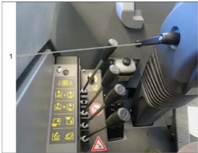
text_image
Industrial control panel with labeled components and warning symbols, showing switches, indicators, and a red indicator light.6.2.4 Begin wet cleaning
text_image
Labeled diagram of a machine tool with numbered components and control panelATTENTION
It is recommended to open the flap of the waste container during sweeping.
It is recommended to close the flap of the waste container during wet cleaning.
1 Display lamp (waste container flap)
2 Open/close flap of the waste container
Note
If the display lamp lights up, then the flap is closed.
→ When the display lamp lights up, actuate the lever and open the flap.
ATTENTION
Risk of accident, risk of injury!
→ Keep unauthorised persons away from the cleaning area.
→ Set up a corresponding warning sign.
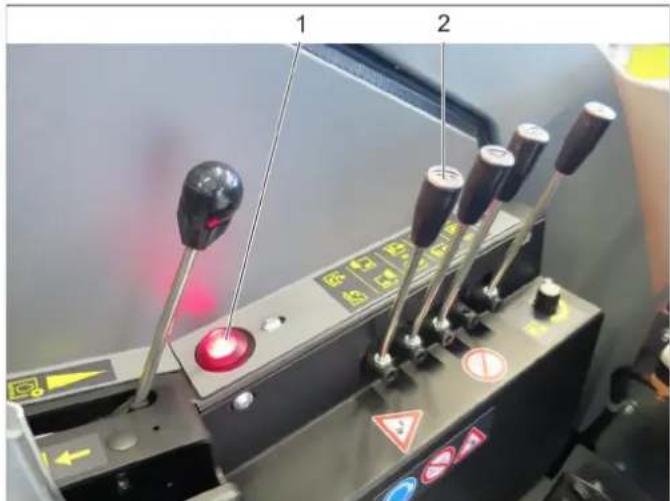
1 Switching brushes on/off
2 Raise/lower the side scrubbing deck
3 Switch for cleaning type: sweeping or scrubbing
4 Water pump switch
5 Hand throttle lever
6 Parking brake
7 Water dispensing, roller brush
8 Water dispensing, side scrubbing deck
→ Set motor speed to Max.
→ Close the flap of waste container
→ Actuate the lever and switch on the brushes; the brushes move downwards.
→ If necessary, adjust the brush contact pressure, see Chapter "Adjust brush contact pressure".
→ Actuate the lever and lower the side scrubbing deck.
→ Switch on the water pump.
→ Select the amount of additional water for side scrubbing deck and brushes.
→ Set the switch to scrubbing cleaning type (to the front).
Note
The suction bar is lowered and the suction turbine starts.
→ Release parking brake.
→ Start with the wet cleaning process.
Note
The dirt that is picked up is collected in the waste water tank and, if necessary, in the waste container.
natural_image
Close-up of a mechanical control panel with four black-handled switches and a red indicator light (no visible text or symbols)6.2.5 End wet cleaning process
→ Stop the machine.
→ Switch off the brushes.
Note
The brushes lift up.
→ Raise the side scrubbing deck.
→ Switch off the water pump.
→ Switch off suction blower.
Note
The suction bar lifts up.
6.2.6 Emptying the waste Water tank
text_image
Labeled diagram of a cleaning or cleaning machine with numbered components
text_image
1 2 3 4 56.2.4.1 Adjusting the brush contact pressure
1 Brush contact pressure (rotary potentiometer)
→ To increase the brush contact pressure - rotate potentiometer clockwise
→ To decrease the brush contact pressure - rotate potentiometer anti-clockwise
■ After cleaning
→ Empty the dirt water reservoir.
→ Empty waste container.
(see Chapter "Sweeping | Emptying the waste container")
→ Clean the device, waste water tank, fresh water tank, suction bar and spray nozzles. (see Chapter "Cleaning").
⚠ WARNING
Risk of personal injury or damage!
→ Always apply and secure the safety support with the tilting device raised.
△CAUTION
Please observe the local provisions regarding the wastewater treatment.
→ Empty the waste water tank only via a suitable collection unit.
ATTENTION
If the waste water tank is full, the suction turbine switches off and the indicator lamp "Waste water tank full" lights up.
1 Safety support
2 waste water tank
3 Dirt water discharge hose
4 Cleaning flap
Depending on the type of dirt, the cleaning flap must be opened regularly and the tank flushed.
→ Empty waste container.
(see Chapter "Sweeping | Emptying the waste container")
→ Afterwards, secure the waste container with the safety support.
The waste water tank drain hose is located on the right-hand side of the device.
1 Closing head
2 Bracket
3 Dosing equipment
4 Dirt water discharge hose
5 Drain hose retainer
→ Remove the drain hose from the holder.
→ Unscrew the lock from the drain hose.
→ The water flow can be reduced by squeezing the dosing unit.
→ Hook the drain hose in the support after emptying and then press it into the retainer.
6.2.7 Emptying the Fresh Water Tank
text_image
1 2 3 4 5The fresh water tank drain hose is located on the left-hand side of the device.
1 Closing head
2 Bracket
3 Dosing equipment
4 Drain hose retainer
5 Drainage hose for fresh water
→ Remove the drain hose from the holder.
→ Unscrew the lock from the drain hose.
→ The water flow can be reduced by squeezing the dosing unit.
→ Hook the drain hose in the support after emptying and then press it into the retainer.
6.3 Sweep
△CAUTION
Risk of damage!
Do not sweep up packing strips, wire or similar objects as this may choke up the suction canal.
→ Do not operate the brushes on the spot.
ATTENTION
To achieve an optimum cleaning result, the driving speed should be adjusted to take specific situations into account. During operation, the waste container should be emptied at regular intervals.
6.3.1 Sweeping mode
text_image
Labeled diagram of a machine tool with numbered components and control panelATTENTION
Make sure that the waste container flap is open.
→ Open the flap of the waste container, see chapter "Opening/closing the flap of the waste container".
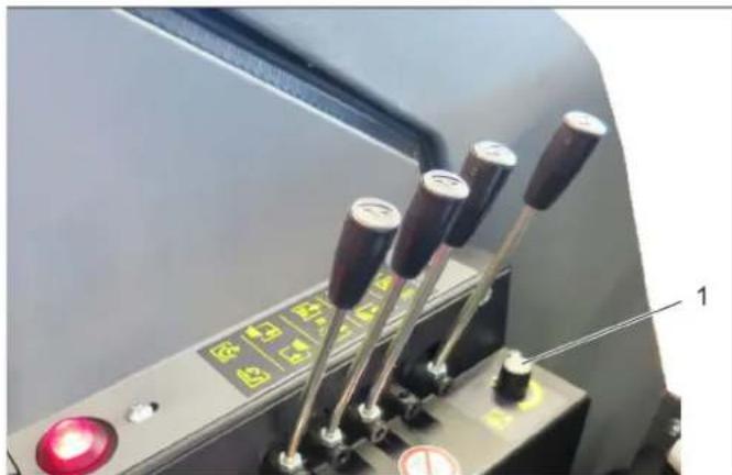
1 Switching brushes on/off
2 Raising/lowering side brushes deck
3 Switch for cleaning type: sweeping or scrubbing
4 Switch for filter dedusting
5 Hand throttle lever
6 Parking brake
→ Set motor speed to Max.
→ Actuate the lever and switch on the brushes; the brushes move downwards.
→ If necessary, adjust the brush contact pressure, see Chapter "Adjust brush contact pressure".
→ Lower the side-brushes.
→ Set the switch to sweeping cleaning type (to the rear).
→ Release parking brake.
→ Begin sweeping.
→ In the meantime: Dedust the dust filter.
6.3.1.1 Cleaning the dust filter
Dedust the dust filter daily. Several times a day as well when working in extremely contaminated areas.
ATTENTION
Risk of damage!
→ Never set the filter dedusting switch to continuous operation.
→ Switch off the suction blower before dedusting.
→ For dedusting, press the filter dedusting switch 4 - 5 times for approx. 5 seconds (no continuous operation!).
6.3.2 Stopping sweeping
→ Stop the machine.
→ Switch off the brushes.
Note
The brushes lift up.
→ The side-brushes lift up.
→ Switch off suction blower.
6.3.3 Emptying waste container
text_image
Labeled diagram of a mobile device showing components 1, 2, 3, and 4, with an inset view of its internal components.6.3.2.1 After cleaning
→ Dedust the dust filter with the filter dedusting switch (see Chapter "Cleaning | Dedusting the dust filter".
→ Empty waste container.
(see Chapter "Sweeping | Emptying the waste container")
→ Clean the device and the waste container daily after work. (see Chapter "Cleaning").
⚠️DANGER
Risk of injury!
→ During the entire emptying process, make sure that no persons or animals are located nearby (waste container swivels out).
⚠️DANGER
Risk of crushing!
→ Never reach into the rod assembly for the drainage mechanism. Do not stay under the raised container.
⚠️DANGER
Danger of tipping!
→ Place the device on an even surface during the emptying process.
⚠️DANGER
Danger of tipping!
→ Do not drive long distances with the waste container raised, drive slowly!
NOTICE
The container can only be tilted and emptied once a set minimum level has been reached.
The high emptying system of the appliance allows the direct disposal of the waste in the waste container into a refuse container (for maximum unloading height see Chapter "Technical data").
1 Waste container
2 Flap of waste container
3 Safety support
Use only with cleaning and maintenance work
4 Raising/lowering high emptying of waste container
5 Open/close flap of the waste container
→ During the entire emptying process, make sure that no persons or animals are located nearby (waste container swivels out).
→ Position the device approximately in front of the collection container.
→ Close the waste container flap (display lamp must be illuminated).
→ Actuate the lever and raise the waste container.
→ With the waste container raised, move slowly over the collection container.
→ Open the flap and empty the waste container.
ATTENTION
Remain seated calmly during the entire emptying procedure (do not stand up from the driver seat), otherwise there is a danger of the seat contact switch switching off during the emptying procedure.
6.4 Turn off device
→ Park the machine on an even surface.
→ Park the machine in a safe and dry place.
→ Turn ignition key to "0" and remove it.
Note
With LPG devices, a switch-off delay lasting a few seconds may occur.
→ Activate parking brake.
→ Gas engine: Close the gas supply.
→ For additional information on shutting down the device, see the Chapter "Storage/decommissioning".
7 Transport
7.1 Loading the vehicle for transport
DANGER
Risk of damage!
→ The appliance is not approved for crane loading.
→ Do not use a fork lift, the appliance could get damaged.
DANGER
Risk of accident, risk of injury!
→ When loading the device, the drive and the parking brake must be operational. The appliance must always be moved up or down slopes by engaging self-propulsion.
⚠ WARNING
Risk of personal injury or damage!
→ Observe the weight of the appliance when you load it!
Net weight (transport weight) 1750 kg
→ Slowly drive the vehicle onto the transport vehicle.
→ If the vehicle is not in running condition, observe Chapter "Towing".
7.1.1 Securing the vehicle
△WARNING
Risk of accident!
→ The vehicle must be secured against shifting during transport.
→ Switch off device.
→ Gas engine: Close the gas supply.
1 Side brushes deck
2 B o l t s
For securing the side brushes deck
→ Press the side brushes deck inwards and secure with bolts.
natural_image
Close-up of a mechanical cleaning or repair device with labeled parts (1, 2), showing no readable text or symbols beyond labels.
natural_image
Industrial cleaning machine with labeled components (no visible text or symbols)→ Secure the wheels of the machine with wheel chocks.
→ Secure the machine with tensioning straps or cables.
Note: Observe markings for fixing points on the base frame (chain symbols). Only unload the appliance on level grounds.
→ When transporting in vehicles, secure the appliance according to the guidelines from slipping and tipping over.
7.2 Towing the vehicle
natural_image
Close-up of a car's front bumper with mesh grille and tire, showing a small attached component labeled '1' (no text or symbols on the main subject)CAUTION
Risk of damage!
→ The vehicle must not be towed faster than at walking speed.
→ Only slowly push or pull the vehicle.
1 Towing eye
To tow the vehicle, the freewheel of the hydraulic drive must be open (see Chapter "Commissioning | Moving device without engaging self-propulsion".
→ The vehicle is towed using the towing eye at the front. The towing eye is not an integral part of the frame, but rather must be attached as required.
8 Storage/decommissioning
DANGER
Risk of personal injury or damage!
→ Consider the weight of the appliance when storing it.
→ Park the device on a level surface in a dry, frost protected area. Protect it against dust by means of covering material.
→ Raise the brushes to prevent the bristles from being damaged.
→ Empty and clean the fresh water tank, the waste water tank and the waste container.
→ Turn ignition key to "0" and remove it.
→ Activate parking brake.
→ Lock the appliance to ensure that it does not roll off.
→ Gas engine
Close the gas inlet.
Caution
Machines must always be parked safely.
The machine - particularly the liquid gas container and its connections - must be inspected by a qualified person at regular intervals, as required by the regional or national guidelines for safe operation.
If the vehicle is not used for a longer period of time, observe the following points:
→ Clean the inside and outside of the vehicle.
→ Change engine oil.
→ Gas engine
Unscrew the gas hose with union nut (use 30 mm spanner). Lock the gas bottle with the safety cap and store upright in a suitable storage area (also see Chapter "Safety instructions").
→ Disconnect the negative terminal of the battery if the appliances is not used for more than 4 weeks.
→ Charge battery approx. every 2 months.
→ Cover the battery and protect it from short circuit.
9 Care and maintenance
9.1 General notes
→ First switch off the appliance and remove the ignition key before performing any cleaning or maintenance tasks on the appliance, replacing parts or switching over to another function.
→ The battery must be disconnected prior to working on the electrical system.
→ Gas engine: Close the gas supply.
→ Maintenance work may only be carried out by approved customer service outlets or experts in this field who are familiar with the respective safety regulations.
9.2 Cowlings
⚠ WARNING
Risk of burns!
→ Allow the vehicle to cool down sufficiently before removing the panels.
→ For the performance of various maintenance tasks the panels must be removed or opened, respectively. A 13 mm wrench is required to open the screws (bayonet).
9.3 Battery
ATTENTION
Using non-rechargeable batteries is prohibited.
Only use batteries and chargers approved by the manufacturer.
Replace batteries with the same battery type only. Prior to disposal of the vehicle, the batteries must be removed and disposed of in accordance with local regulations.
9.3.1 Safety notes regarding the batteries
ATTENTION
Follow accident prevention regulations as well as DIN VDE 0510, VDE 0105 T.1.
Please observe the following warning notes when handling batteries:
 | Observe information in the user manual of the battery and on the battery as well as in these operating instructions! |  | Danger of causticization! | |
 | Wear an eye shield! | Fi |  | |
 | Keep away children from acid and batteries! |  | Warning note! | |
 | Risk of explosion! Disp |  | ||
 | Fire, sparks, open light, and smoking not allowed! |  | Do not throw the battery in the dustbin! |
DANGER
Risk of fire and explosion!
→ Do not place tools or similar items on the battery. Risk of short-circuit and explosion.
→ Smoking and open flames must be strictly avoided.
→ Rooms where batteries are charged must have good ventilation because highly explosive gas is emitted during charging.
Danger of causticization!
→ Use caution with leaking batteries (sulphuric acid may leak).
Risk of injury!
→ Ensure that wounds never come into contact with lead. Always clean your hands after working on batteries.
9.3.2 Procedures in the event of unintentional release of battery acid
When used normally, and when observing the instructions, lead-acid batteries do not pose any risk.
However, keep in mind that lead-acid batteries contain sulphuric acid which can cause chemical burns and corrosion.
→ If there is spillage or, if the battery is leaking, acid is escaping, lay down a binding agent such as sand. Do not let it reach the sewer system, soil or a body of water.
→ Neutralise the acid with lime/baking soda and dispose of it according to local regulations.
→ Contact a waste management company to dispose of faulty batteries.
→ Rinse thoroughly with lots of clear water if acid gets into the eye or comes in contact with the skin.
→ Then consult a doctor immediately.
→ Wash off the acid If it comes in contact with the clothes.
→ Change clothing.
9.3.3 Installing and connecting the battery
text_image
Labeled diagram of a 3D printer internal structure with numbered components9.3.4 Charging battery
⚠ Danger
Risk of injury! Comply with safety regulations on the handling of batteries. Observe the directions provided by the manufacturer of the charger.
⚠️Danger
Charge the battery only with an appropriate charger.
ATTENTION
The battery must only be loaded by a qualified operator.
ATTENTION
The battery must only be installed and removed by a qualified operator.
1 Support
2 Angle bracket
3 Battery
4 Seat contact switch
5 Cover with driver seat
→ Tilt the cover upwards and secure it with the support.
→ Insert battery in battery mount.
→ Attach the battery by means of an angle bracket.
→ Connect pole terminal (red cable) to positive pole (+).
→ Connect the pole terminal (black cable) to the negative terminal (-).
ATTENTION
Before removing the battery, make sure that the negative pole lead is disconnected. Check that the battery pole and pole terminals are adequately protected with pole grease.
ATTENTION
When the battery is charged, first remove the charger from the mains and then disconnect it from the battery.
→ Disconnect the connecting cable from the battery at the positive terminal.
→ Charger connect to battery.
→ Plug in mains connector and switch on charger.
→ Charge battery using lowest possible level of charging current.
9.4 Maintenance intervals
Observe the inspection checklist!
The elapsed-time counter shows the timing of the maintenance intervals.
9.4.1 Maintenance by the customer
Note: Where maintenance is carried out by the customer, all service and maintenance work must be undertaken by a qualified specialist. If required, a specialised Kärcher dealer may be contacted at any time.
Note: For description, see section on Maintenance work.
9.4.1.1 Daily before starting operations
→ Check fill level of fuel tank.
→ Check engine oil level.
→ Check cooler water level.
→ Clean / replace the air filter of the internal combustion engine
→ Empty waste container.
→ Empty the dirt water reservoir.
→ Fill fresh water tank as needed.
→ Check brushes for wear and damage.
→ Check suction lip of the suction bar for wear and damage.
→ Check/clean the water and suction system.
→ Check function of all operator control elements.
→ Check appliance for damages.
→ Clean the dust filter with the filter cleaning button.
9.4.1.2 Weekly
→ Check leakiness of fuel or gas connections.
→ Check fluid level of battery. (only with low-maintenance battery)
→ Clean the water cooler.
→ Clean the hydraulic oil cooler.
→ Check hydraulic unit.
→ Check the hydraulic oil level.
→ Check brake fluid status.
→ Check the pad for wear, replace if required.
→ Check the container lid and lubricate it.
→ Use the grease gun to lubricate the lubricating nipple on the suction bar.
9.4.1.3 Every 150 operating hours
→ Use the grease gun to lubricate the lubricating nipple on the waste container.
→ Use the grease gun to lubricate the lubricating nipple on the brush head excavation.
→ Use the grease gun to lubricate the lubricating nipple on the bearing of the engine.
→ Check the areas around the suspension, wheels, steering and combustion engine for loose screws and re-tighten them if necessary.
9.4.1.4 Every 200 operating hours
→ Replace motor oil + motor oil filter
→ Check hydraulic connections for leakage and re-tighten them if necessary.
9.4.1.5 Every 1500 operating hours
→ Replace the dust filter.
9.4.1.6 After wearing has taken place
→ Replace sealing strips.
→ Replace brushes.
9.4.2 Maintenance by Customer Service
Note: In order to safeguard warranty claims, all service and maintenance work during the warranty period must be carried out by the authorised Kärcher Customer Service in accordance with the maintenance booklet.
→ All service and maintenance work performed during Customer Service maintenance must be carried out by the authorised Kärcher Customer Service in accordance with the inspection checklist (ICL).
→ Retighten hydraulic connections as needed.
9.5 Inspection and maintenance work
9.5.1 General notes on safety
⚠️DANGER
Risk to life
→ When carrying out repairs, remove the vehicle from the danger zone of passing traffic and wear reflective clothing.
WARNING
Risk of personal injury or damage!
→ Risk of injury due to engine overrun. Once the engine has been switched off, wait for 5 seconds. Stay well clear of the working area for this time.
→ Be careful when using high-pressure cleaners for cleaning!
Radiator fins, hydraulic hoses and valves, seals and electric and electronic components must not be cleaned with the high-pressure cleaner.
→ Risk of injury when vehicle accidentally starts up. Remove the ignition key and disconnect the battery prior to performing cleaning and maintenance tasks on the vehicle.
→ Maintenance on the hydraulic system must only be carried out by trained personnel.
9.5.2 Secure raised waste container
text_image
1 2 2⚠ WARNING
Risk of personal injury or damage!
→ Always apply and secure the safety support with the tilting device raised.
△CAUTION
Risk of burns!
→ Allow the vehicle to cool down sufficiently before performing any maintenance and repair work.
Do not touch hot parts of the hydraulics, the hydrostatic drive motor, the combustion engine and the exhaust system.
ATTENTION
Do not allow fluids such as motor oil, hydraulic oil, brake fluid, diesel or coolant to enter the soil. Please protect the environment and dispose of fluids in an environmentally responsible way.
⚠️DANGER
Risk of injury!
→ Always apply the safety rod when the waste container is raised.
→ Perform the safeguarding only from outside the hazard zone.
1 Waste container
2 Safety rod
→ Lift the waste container and secure by means of cylinder support.
→ After maintenance work, pull the cylinder supports back out again and fold at the top into the retainer.
9.5.3 Check engine oil level and top up, if required
natural_image
Close-up of a blue industrial engine bay with visible components and wiring (no text or symbols)1 Oil dipstick
2 Oil filler cap
→ Park the vehicle on a level surface.
→ Pull out oil dipstick.
→ Wipe off oil dipstick and insert.
→ Pull out oil dipstick.
9.5.3.1 Check the motor oil level
→ Read the value of the oil level.
→ Insert the oil dip again.
- The oil level must lie between "MIN" and "MAX" marking.
- Add motor oil if the oil level is below the "MIN" marking.
9.5.3.2 Fill in motor oil
ATTENTION
An oil level that is too high leads to damages of the engine by overheating. If the oil level exceeds the "MAX" mark, oil must be drained until the correct oil fill level has been reached.
→ Remove the oil filler cap.
→ Fill in motor oil.
Oil grade: Refer to chapter "Technical data"
→ Do not fill oil above the "MAX" marking.
→ Close oil cap.
→ Wait at least 5 minutes.
→ Check engine oil level.
9.5.4 Change the motor oil and the oil filter
text_image
Industrial machinery diagram with numbered labels pointing to components like pipes, valves, and tanks⚠ WARNING
Risk of burns!
To change the motor oil and motor oil filter, allow the vehicle to cool down until there is no longer a risk of burns.
1 Oil filler cap
2 Oil dipstick
3 Engine oil filter
Note
A warm motor facilitates the draining of the motor oil.
→ Prepare a collection container for at least 10 litres of oil.
→ Switch off engine.
→ Unscrew oil drain plug.
→ Remove oil cap.
→ Drain off oil.
→ Unscrew the oil filter.
→ Clean the intake and sealing areas.
→ Coat the washer of the new oil filter with oil before fitting it.
→ Fit in the new oil filter and tighten it by hand.
→ Screw in the oil drain plug with the new seal. Tightening torque: Nm
→ Fill in motor oil.
For oil type and filling quantity refer to Chapter "Technical specifications".
→ Close oil cap.
→ Let the motor run for approx. 30 seconds.
→ Wait at least 5 minutes.
→ Check engine oil level.
→ Check for leaks.
→ Deliver the old oil to the respective collection centres.
9.5.5 Check brake fluid status
text_image
Labeled mechanical assembly diagram showing components numbered 1, 2, and 3 with arrows indicating movement or force direction.1 Lever for steering wheel adjustment
2 Brake fluid container
3 Filling level
→ If necessary, refill DOT brake fluid currently commercially available.
→ Have the brake fluid changed by Customer Service in accordance with the inspection checklist (ICL).
9.5.6 Check hydraulic oil level and refill oil
text_image
Labeled diagram of a mechanical or optical device with numbered components, likely from an engineering or lab context.ATTENTION
In order to avoid operational problems, utmost cleanliness is vital for all check and maintenance work.
Even the finest contamination in the hydraulic system can cause severe faults; therefore, the system is fitted with a hydraulic oil filter.
1 Hydraulic oil tank
2 Sight glass hydraulic oil
3 Hydraulic oil fill neck
→ Check the hydraulic oil level and refill hydraulic oil if necessary.
Oil grade: Refer to chapter "Technical data"
→ The oil level must be within the viewing glass.
9.5.7 Replacing the hydraulic oil filter
text_image
Labeled mechanical assembly diagram showing components with numbered parts and visible pipes and labels⚠ WARNING
Risk of burns!
→ Allow cooling system to cool down sufficiently prior to working on the appliance.
ATTENTION
Risk of damage!
→ Have authorised Customer Service perform any work to be done on the hydraulic system.
Have the hydraulic oil filter changed by Customer Service in accordance with the inspection checklist (ICL).
1 Stop cock
2 Hydraulic oil filter
→ Close the stop valve.
→ Use suitable tools to unscrew the hydraulic oil filter.
→ Coat the washer of the new oil filter with oil before fitting it.
→ Fit in the new oil filter and tighten it by hand.
→ Open locking valve.
→ Check the hydraulic oil level and refill hydraulic oil if necessary.
9.5.8 Checking the coolant level and topping up coolant
WARNING
Risk of burns!
Do not open or touch the radiator or parts of the cooling system while the motor is hot.
△CAUTION
→ Only top up coolant when the engine is cool.
→ Use a water and antifreeze mixture to refill.
→ For coolant refer to chapter "Technical data"
→ Do not mix different antifreeze types.
→ Use only soft water for the water and antifreeze mixture.
natural_image
Interior view of a vehicle engine bay with hoses and components (no visible text or symbols)1 Cover
2 Coolant expansion tank
→ Check filling level while the motor is cold.
→ Check the filling level in the coolant expansion tank.
Note
The correct coolant level is in the middle of the expansion tank.
9.5.8.1 Refilling coolant in the expansion tank
→ Check filling level while the motor is cold.
→ Unscrew the lid.
→ Refill the expansion tank.
Note
The correct coolant level is in the middle of the expansion tank.
→ Close the lid for the equalising reservoir.
→ Start the engine and let it warm up.
→ Check the filling level in the coolant expansion tank.
→ If the coolant level is too low, switch off the motor and allow it to cool down. Pour the missing amount of coolant into the coolant expansion tank.
Note
The correct coolant level is in the middle of the expansion tank.
9.5.9 Cleaning and replacing the air filter
text_image
1 2 1 4 31 Locking
2 Air filter housing
3 Filter cartridge
4 Safety cartridge
→ Open the lock.
→ Remove the air filter housing.
→ Remove the filter cartridge.
→ Clean the interior of the air filter reservoir.
→ Only remove the safety cartridge if it is being replaced.
→ Clean the filter insert: Tap out the dust on a hard surface, blow out from inside to outside with compressed air at max. 30 psi (2 bar).
→ The seal face and filter insert must be clean and free of damage upon installation.
→ Insert the cleaned filter insert.
Important: A severely contaminated or damaged filter insert must be replaced.
→ If the filter insert is being replaced, replace the safety cartridge too.
Important: No dust is allowed to enter through the suction opening when replacing the filter insert and safety cartridge
9.5.10 Greasing the vehicle
ATTENTION
Risk of functional disturbances. Do not let the V-belts get in contact with the grease.
→ Grease the grease nipples in accordance with the maintenance intervals using a grease gun.
→ Use high quality multi-purpose grease and use grease gun to lubricate.
9.6 Replacing brushes
Two brushes are installed in the device which should be replaced when they become worn.
→ One brush is replaced from the left-hand side and the other from the right-hand side. The procedure is the same.
→ Clean the roller brush retainers before inserting the new brushes.
→ The brushes are inserted in the reverse sequence.
natural_image
Close-up of a robotic car wheel with a red and black component, showing a curved cable and labeled point A (no text or symbols on the vehicle itself)
natural_image
Mechanical assembly diagram showing a cam mechanism with labeled component B (no text or symbols beyond label)
natural_image
Close-up of a mechanical assembly with visible components and wiring (no text or symbols)
natural_image
Close-up of a cleaning brush head with visible wiring and components, no text or symbols present9.6.1 Adjusting the sweeping level (brush contact pressure)
text_image
A 5-6 cm A 5-6 cm→ The sweeping level should be between 5-6 cm.
The adjustment of the sweeping level (brush contact pressure) is set with the rotary potentiometer in the control panel.
→ Rotate the potentiometer to the right until the lowering brushes exhibit the correct sweeping level (brush contact pressure).
→ Is the sweeping level too large, rotate the potentiometer back.
9.7 Replacing side brushes
natural_image
Close-up of a mechanical gear assembly with labeled parts (1 and 2), no readable text or symbols beyond labels1 Side brushes
2 Screws
→ Loosen 4 screws and remove the side brushes.
→ Insert new side brushes and fasten with four screws.
9.7.1 Converting the side deck
→ The conversion to the side scrubbing deck or side brushes deck must be accomplished by Customer Service; the sweeping level and the cleaning parameters must be reset after the conversion.
9.8 Cleaning
△DANGER
Risk of injury!
→ Remove the ignition key prior to performing any cleaning and maintenance tasks!
→ Park the vehicle on a level surface.
→ Turn ignition key to "STOP" and remove it.
→ Activate parking brake.
9.8.1 Cleaning/replacing dust filter cartridges
△CAUTION
Health hazard!
→ Wear a dust mask when working around the dust filter. Observe safety regulations on the handling of fine particles.
→ Wear an eye shield!
ATTENTION
Do not use any hard objects for cleaning!
The dust filter cartridges are responsible for filtering and retaining the dust suctioned up by the suction turbine during sweeping.
- Dedust the dust filter with the filter dedusting switch each day during and after cleaning (see Chapter "Cleaning | Dedusting the dust filter".
- Remove and clean the dust filer from time to time.
- Complete replacement every 1500 operating hours!
1 Suction blower cover
2 Handle
3 Screw
→ Open the screw and tilt the suction blower cover towards the rear.
text_image
Labeled diagram of a mechanical device showing components 1, 2, and 3 with orange warning light indicator
text_image
Labeled diagram of a mechanical device showing components 1, 2, and 3 with visible wiring and components.9.8.2 Cleaning/replacing the flat fold filter
text_image
1 2 3 49.8.3 Cleaning the vehicle
1 N u t s (4 x)
2 Filter dedusting rail
3 Dust filter cartridges (5x)
→ Screw out 4 nuts.
→ Remove the filter dedusting rail.
→ Take out five dust filters and five sealing rings.
→ Clean the dust filter with compressed air from the outside to the inside.
→ During installation, take care to ensure that all sealing rings are seated correctly in the guides.
ATTENTION
Do not use any hard objects for cleaning!
The flat fold filter is responsible for protecting the suction blower of the wet cleaning.
- Remove and clean the flat fold filter as needed.
- Replace every 100 operating hours!
1 L o c k
2 Sealing band
3 Cover, suction blower
4 Flat fold filter
→ Open the lock and lock strap.
→ Remove cover.
→ Take out the flat folded filter.
→ Clean under flowing water with a soft brush, allow to dry before installation.
→ Ensure at the time of installation that the flat fold filter is seated correctly in the guide.
Clean vehicle daily after finishing work.
⚠️DANGER
Risk of injury!
→ Wear dust mask and protective goggles.
△CAUTION
Risk of damage!
→ Be careful when using high-pressure cleaners for cleaning!
Radiator fins, hydraulic hoses and valves, seals and electric and electronic components must not be cleaned with the high-pressure cleaner.
→ When cleaning the vehicle with a high-pressure cleaner, the respective safety instructions must be observed.
→ Do not use aggressive cleaning agents.
→ Only wash the vehicle while the motor is switched off to protect the air filter.
→ Clean the machine with a damp cloth which has been soaked in mild detergent.
→ Check motor for soiling; if necessary, clean by means of a brush, compressed air or low water pressure
9.8.4 Clean the waste water tank
text_image
1 2 3 4 4 5
text_image
Labeled diagram of a cleaning or cleaning machine with numbered components1 Dirt water discharge hose
2 waste water tank
3 Signal transmitter
Switches off the suction turbine when the waste water tank is filled
4 L o c k
5 Cover waste water tank
→ Clean the waste water tank after completion of work.
→ Before cleaning, empty the waste water tank, see Chapter "Wet cleaning | Emptying the waste water tank".
1 Safety support
2 waste water tank
3 Dirt water discharge hose
4 Cleaning flap
Open for cleaning
→ For thorough cleaning, open the cleaning flap.
→ Use a water hose to spray out the interior of the waste water tank.
→ After cleaning, check the function of the signal generator.
9.8.5 Clean the fresh water reservoir
text_image
Labeled mechanical assembly diagram showing three numbered components in a machine tool or enclosure.1 Fresh water tank
2 Fresh water tank cover
3 Filling level display
4 Drainage hose for fresh water
→ Flush out the fresh water tank with clear water after finishing work.
→ Empty residual water through the drain hose.
9.8.6 Cleaning sealing lips, suction bar and spray nozzles
text_image
Technical diagram of a cleaning or anti-damperated robotic vehicle with numbered components labeled 1, 2, and 3.1 Vacuum bar
2 Suction hose
3 Seal strip
→ Clean suction bar and suction hose.
→ Clean the side sealing strips.
→ Clean the spray nozzles of the side scrubbing deck and roller brush.
9.8.7 Clean the waste container
text_image
Labeled diagram of a robotic device showing components 1, 2, and 3 with visible wiring and mounting hardware.9.8.8 Clean water filter.
text_image
1 2 39.8.9 Clean the hydraulic oil cooler and the radiator
natural_image
Close-up of a heat exchanger or cooling unit with visible cooling pipes and heat sinks (no text or symbols)WARNING
Risk of personal injury or damage!
→ Always apply and secure the safety support with the tilting device raised.
→ Do not use any high-pressure cleaners or water jet for cleaning (dust filter cartridges)!
ATTENTION
Allow dust filter cartridges that have become wet to dry before resuming work!
1 Waste container
2 Flap of waste container
3 Safety support
→ Clean interior of waste container with compressed air and a brush.
→ With stubborn contamination: Clean interior of waste container with water and a brush, leave the waste container open to allow it to dry out.
1 Water filter
2 Water filter casing
3 Stop cock (Open position)
→ Close the stop valve.
→ Unscrew the water filter casing.
→ Take out and clean or replace the water filter insert.
→ Open the stop cock again after installation.
1 Water cooler
2 Hydraulic oil cooler
A dirty radiator will easily cause overheating, therefore each day:
→ Check radiator and radiator grille for soiling.
→ Remove soiling by means of a soft brush, compressed air (max. 5 bar) or low water pressure.
9.9 Replacement tasks
9.9.1 Fuses

text_image
X173.1 X173.1 1 2 3 4
text_image
1 2 3 4 5 6 7 8 A B 9 10 11 12 13 14 15 16The customary fuses are located to the right under the steering wheel.
1 Cover fuse box
2 Safety lid seal
3 Fuse box
4 Fuses
→ Test the fuses, if necessary replace with new fuses of the same capacity.
| A Fuse box 1 | |
| 1 Tachometer + diagnosis sensor 5 A | |
| 2 Brake light 7.5 A | |
| 3 Beacon light 10 A | |
| 4 Instruments, switches 3 A | |
| 5 Heating 10 A | |
| 6 Dipped beamTimer for raising roller brush | 15 A |
| 7 Optional 15 A | |
| 8 Motor stop 15 A |
| B Fuse box 2 | |
| 1 Parking light 3 A | |
| 2 Dipped beam 3 A | |
| 3 Warning system | 15 A |
| 4 Warning system | 10 A |
| 5 Warning system Horn | 7.5 A |
| 6 Warning system | 10 A |
| 7 Solenoid valve of waste container | 5 A |
| 8 Instruments, switches 10 A |
9.10 Accessories
You can procure the spare parts and the attachments from your dealer or your KÄRCHER branch office.
| Name Order No. Remark | ||
| Roller brush, standard | 6.680-368.0 | For general cleaning (included with the appliance as part of the scope of delivery) |
| Roller brushes, hard | 6.680-369.0 | For stubborn contamination and basic cleaning (for hard surfaces only) |
| Side scrubbing deck brush 6.680-338.0 For general cleaning | ||
| Side scrubbing deck brush, hard | 6.680-339.0 | For stubborn contamination and basic cleaning (for hard surfaces only) |
| Side brushes 6.680-335.0 For general cleaning | ||
| Hard side-brushes 6.680-336.0 For stubborn contamination and basic cleaning (for hard surfaces only) | ||
| Suction bar squeegee blade, rubber | 6.680-372.0 | For general cleaning (included with the appliance as part of the scope of delivery) |
| Suction bar squeegee blade, polyurethane | 6.680-373.0 Oil-resistant | |
| Wheel 6.680-410.0 Standard accessories | ||
| Wheel, super traction | 6.680-377.0 | For slippery surfaces and steep slopes |
| Splash guard, side scrubbing deck | 6.680-371.0 | |
| Dust lip, rear main brush 6.680-362.0 | ||
| Splash guard, rubber, main brush | 6.680-220.0 Standard accessories | |
| Splash guard, polyurethane, main brush | 6.680-370.0 Oil-resistant | |
| Dust protection rubber, lateral | 6.680-278.0 | |
| Dust protection seal, lateral | 6.680-276.0 | |
| Dust protection rubber, lateral | 6.680-361.0 | |
| Dust filter cartridge, polyurethane | 6.680-374.0 Appliance requires 5 pieces | |
| Flat fold filter, polyurethane | 6.680-534.0 For the waste water tank | |
10 Troubleshooting
10.1 Faults with display
| Display | Cause | Remedy | By whom |
| Warning lamp for motor temperature lights up | Engine is overheated | Set the engine speed to idle. | Operator |
| Clean radiator (see Chapter "Maintenance and care"). | |||
| Check the level of cooling liquid in the engine. | |||
| Warning lamp for hydraulic oil temperature | Hydraulic oil temperature too high. | Let the motor idle until the warning light goes out. | Operator |
| Clean radiator (see Chapter "Maintenance and care"). | |||
| Check the hydraulic oil level. | |||
| Warning lamp for battery lights up | Battery is not being charged | Call Customer Service. | Operator |
10.2 Faults without display
| Fault RemedyThe vehicle cannot be started S | it on the driver seat. |
| Charging or replacing battery | |
| Diesel engine: Fill in fuel, bleed the fuel systemGas engine: Open the stop cock of the gas bottle, replace the empty gas bottle | |
| Replace defective fuse. | |
| Diesel engine: Clean or replace fuel filterGas engine: Observe the installation position of the gas bottle, the connection must face downwards | |
| Check petrol pipes for leaks. | |
| Contact the authorised customer service. | |
| Engine is running erratically Cle | an or replace air filter |
| Check filling level of fuel tank | |
| Diesel engine: Clean or replace fuel filterGas engine: Observe the installation position of the gas bottle, the connection must face downwards | |
| Check fuel pipes, connections and joints and maintain them if required | |
| Contact the authorised customer service. | |
| Engine is running, but vehicle is only driving slowly or is not driving at all | Check the hydraulic oil level. |
| Release parking brake | |
| Close the screw for the freewheel (hydraulic pump) | |
| Increase engine speed | |
| Open the stop cock on the hydraulic filter or replace the hydraulic filter if clogged | |
| Contact the authorised customer service. | |
| Vehicle moves despite acceleration pedal being in neutral position | Have the setting of the accelerator pedal checked by Customer Service. |
| Waste container does not raise or lower | Check the hydraulic oil level. |
| Check whether the flap of the waste container is closed | |
| Open the stop cock on the hydraulic filter or replace the hydraulic filter if clogged | |
| Increase engine speed | |
| Waste container too full/heavy | |
| Contact the authorised customer service. | |
| Large amount of wear and tear on the brushes | Reduce the brush contact pressure. |
| Cleaning surface too abrasive, possibly use other brushes. | |
| Brushes do not turn or turn too slowly | Check the hydraulic oil level. |
| Open the stop cock on the hydraulic filter or replace the hydraulic filter if clogged | |
| Increase engine speed | |
| Remove ropes and tapes | |
| Contact the authorised customer service. | |
| Wet cleaning: Cleaning result insufficient | Set the engine correctly |
| Increase brush contact pressure. | |
| Reduce working speed. | |
| Switch on the suction blower. | |
| Fill up fresh water reservoir. | |
| Check the water supply dosing | |
| Remove ropes and tapes | |
| Brushes worn, replace them | |
| Clean/adjust/replace squeegee blade | |
| Clean the suction channel | |
| Fault Remedy | |
| Wet cleaning: Cleaning fluid on cleaning surface | Replace worn vacuum bar seals |
| Switch on the suction blower. | |
| Waste water tank empty, suction turbine was switched off by signal generator | |
| Clean the vacuum bar | |
| Clean/adjust/replace squeegee blade | |
| Clean the suction channel | |
| Contamination, Clean/replace flat fold filter | |
| Adjust vacuum bar correctly | |
| Wet cleaning: No cleaning fluid | Clean lines and spray nozzles |
| Fill up fresh water reservoir. | |
| Switch on the water pump | |
| Open water volume supply dosing | |
| Clean water filter. | |
| Sweeping: Cleaning result insufficient | Increase engine speed |
| Increase brush contact pressure. | |
| Empty full waste container | |
| Open the flap of waste container | |
| Reduce working speed. | |
| Brushes worn, replace them | |
| Dedust contaminated dust filter with filter dedusting. | |
| Clean or replace dust filter if it is contaminated or defective | |
| Remove ropes and tapes | |
| Clean/adjust/replace squeegee blade | |
| Contact the authorised customer service. | |
| Sweeping: Dust and dirt coming out of the waste container | Empty full waste container |
| Switch on the suction blower. | |
| Close the flap of waste container | |
| Replace defective seal from flap of the waste container | |
| Brush or suction bar does not lower/raise up | Contact the authorised customer service. |
11 Specifications
| B 300 RI D: Diesel engine | B 300 RI LPG: Gas engine | ||
| Machine data | |||
| Length x width x height mm 2490 x 1570 x 1860 2490 x 1570 x 1860 | |||
| Height with protective roof for the driver, small mm 2020 2020 | |||
| Height with protective roof for the driver, large mm 2120 2120 | |||
| Net weight (transport weight) kg 1750 1775 | |||
| Permissible overall weight kg 2635 2635 | |||
| Drive speed, forward km/h max. 12 max. 12 | |||
| Drive speed, reverse km/h max. 5 | max. 5 | ||
| Maximum working speed | km/h | 10,7 | 10,7 |
| Usage duration when tank is full | h | 5 | 5 |
| Climbing capability (max.) | % | 12 | 12 |
| Turning radius | mm 3150 | 3150 | |
| Theoretical surface cleaning performance | mm | 16.550 | 16.550 |
| Working width without side deck | mm 1045 | 1045 | |
| Working width with side deck | mm | 1350 (1400) | 1350 (1400) |
| Working width with two side decks (optional) | mm | 1655 (1755) | 1655 (1755) |
| Working width, suction bar | mm 1440 | 1440 | |
| Volume of waste water tank | l | 270 | 270 |
| Volume, fresh water reservoir | l | 271 | 271 |
| Volume of waste container | l | 180 | 180 |
| Max. unloading height | mm 1560 | 1560 | |
| Brushes (wet cleaning) | |||
| Roller brush diameter | mm | 300 | 300 |
| Roller brush width | mm 1045 | 1045 | |
| Side brushes diameter | mm | 410 | 410 |
| Brushes (sweeping) | |||
| Roller brush diameter | mm | 300 | 300 |
| Roller brush width | mm 1045 | 1045 | |
| Side brush diameter | mm | 600 | 600 |
| Motor | |||
| Type | -- | Kubota V1505 (E4B) | Kubota WG1605-L-E3 |
| Type | -- | 4-cylinder 4-stroke diesel engine | 4-Cylinder 4-stroke gas engine |
| CO2Emission according to the measurement procedure of EU regulation 2016/1628 (level V) | g/kWh | 1018,0 | 1030,6 |
| Cooling type | -- | Water cooling | Water cooling |
| Cylinder capacity | cm3 | 1498 1537 | |
| Motor output | kW/HP | 18,5/24,8 2300 1/min | 36/48 2550 1/min |
| Electrical system | |||
| Battery | V, Ah | 12, 80 Ah | 12, 80 Ah |
| Fuel | |||
| Fuel type | Diesel | LPG LPG mixtures of propane and butane are permitted. The propane content must be at least 90%. | |
| Fuel tank capacity | l | 30 | --- |
| Gas cylinder | --- | 11 kg / 20 litres (replacement cylinder) | |
| Engine oil type >25 °C SAE30, SAE10W-30, | SAE15W-40 | SAE30, SAE10W-30, SAE15W-40 | |
| 0 - 25 °C SAE20, SAE10W-30 SAE20, SAE10W-30 | |||
| < 0 °C SAE10, SAE10W-30 SAE10, SAE10W-30 | |||
| Engine oil volume I 6 6 | |||
| Coolant (SAE J814C) -- Stilmoil Antifrost Stilmoil Antifrost | |||
| Hydraulic oil as per DIN 51524, part 3 Agip Rotra ATF Agip | Rotra ATF | ||
| Hydraulic oil volume I 30 30 | |||
| Greases | |||
| For points to be lubricated manually | -- | Multi-purpose grease | Multi-purpose grease |
| Tyres | |||
| Front tyres | 1x | ø 452 mm (marangoni) | ø 452 mm (marangoni) |
| Rear tyres | 2x ø 457 mm (marangoni) ø 457 mm (marangoni) | ||
| Noise emission Values determined to EN ISO 3744 | |||
| Sound pressure level L_pA | dB(A) | 92 | 87 |
| Uncertainty K_pA | dB(A) | 2 2 | |
| Sound power level L_WA | dB(A) | 103 | 104 |
| Uncertainty K_WA | dB(A) | 3 3 | |
| Machine vibrations Values determined as per EN 60335-2-72 | |||
| Hand-arm vibration value | m/s2 | 0,43 | 0,91 |
| Uncertainty K (hand-arm vibration) | m/s2 | 0,06 | 0,13 |
| Body vibration value | m/s2 | 0,97 | 1,2 |
| Uncertainty K (body vibration) | m/s2 | 0,11 | 0,13 |
| Leg vibration value | m/s2 | 0,84 | 1,1 |
| Uncertainty K (leg vibration) | m/s2 | 0,09 | 0,12 |
12 EU Declaration of Conformity
We hereby declare that the machine described below complies with the relevant basic safety and health requirements of the EU Directives, both in its basic design and construction as well as in the version put into circulation by us. This declaration shall cease to be valid if the machine is modified without our prior approval.
Product: Scrubbing vacuum cleaner
Type: 2.004-xxx
Relevant EU Directives
2006/42/EC (+2009/127/EC)
2014/30/EU
2000/14/EC
2014/53/EU (TCU)
Applied harmonized standards
EN 60335-1
EN 60335-2-72
EN 62233: 2008
EN 55012: 2007 + A1: 2009
EN 61000-6-2: 2005
(TCU)
EN 300 328 V2.1.1
EN 300 440 V2.1.1
EN 301 511 V12.5.1
EN 300 330 V2.1.1
Applied conformity evaluation method
2000/14/EC: Appendix V
Sound power level dB(A)
B 300 R I LPG
Measured: 104
Guaranteed: 107
B 300 R I Diesel
Measured: 103
Guaranteed: 106
The signatories act on behalf of and with of the authority of the company management.

H. Jenner
Chairman of the Board of Management

S. Reiser
Director Regulatory Affairs & Certification
Documentation supervisor:
S. Reiser
Alfred Kärcher SE & Co. KG
71364 Winnenden (Germany)
Tel.: +49 7195 14-0
Fax: +49 7195 14-2212
Winnenden, 2022/02/01
13 Declaration of Conformity
We hereby declare that the product described below complies with the relevant provisions of the following UK Regulations, both in its basic design and construction as well as in the version put into circulation by us. This declaration shall cease to be valid if the product is modified without our prior approval
Product: Scrubbing vacuum cleaner
Type: 2.004-xxx
Currently applicable UK Regulations
S.I. 2008/1597 (as amended)
S.I. 2016/1091 (as amended)
S.I. 2001/1701 (as amended)
S.I. 2017/1206 (as amended) (TCU)
Applied harmonized standards
EN 60335-1
EN 60335-2-72
EN 62233: 2008
EN 55012: 2007 + A1: 2009
EN 61000-6-2: 2005
(TCU)
EN 300 328 V2.1.1
EN 300 440 V2.1.1
EN 301 511 V12.5.1
EN 300 330 V2.1.1
Applied conformity assessment procedure
S.I. 2001/1701 (as amended): Schedule 8
Sound power level dB(A)
B 300 R I LPG
Measured: 104
Guaranteed: 107
B 300 R I Diesel
Measured: 103
Guaranteed: 106
The signatories act on behalf of and with of the authority of the company management.

H. Jenner
Chairman of the Board of Management

S. Reiser
Director Regulatory Affairs & Certification
Documentation supervisor:
S. Reiser
Alfred Kärcher SE & Co. KG
71364 Winnenden (Germany)
Tel.: +49 7195 14-0
Fax: +49 7195 14-2212
Winnenden, 2022/02/01
text_image
Labeled diagram of a vehicle's interior components with numbered parts, showing dashboard and control panel layout.text_image
Labeled diagram of industrial equipment showing numbered components including switches, warning symbols, and safety warnings.natural_image
Close-up of a car's front bumper with mesh grille and tire, showing no visible text or symbolsnatural_image
Interior view of a vehicle engine bay with visible hoses, valves, and components (no text or symbols)1 C ou v e r c l e
text_image
Labeled interior view of a mechanical or electronic device with numbered componentsDANGER
Risque d'accident !
text_image
Labeled interior view of a vehicle's steering wheel and dashboard with numbered parts, showing control buttons and navigation elements.natural_image
Close-up of an orange gas cylinder with a yellow connector and coiled tubing, no visible text or symbolsnatural_image
Interior view of a mechanical device with numbered components (1, 2, 3) and no visible text or symbols on the main structure.Remarque
text_image
Industrial control panel with labeled components and warning symbolstext_image
Labeled mechanical device diagram with numbered components and control panelATTENTION
natural_image
Close-up of a mechanical control panel with four vertical sliders and a digital display, no visible text or symbolstext_image
Labeled diagram of a cleaning or cleaning machine with numbered components
text_image
1 2 3 4 5text_image
Labeled mechanical device interior with numbered components and control panelATTENTION
text_image
Labeled diagram of a mobile industrial testing machine with numbered components and an inset showing its internal components.natural_image
Close-up of a cleaning or cleaning machine component with labeled parts (1 and 2), no readable text or symbols beyond labels.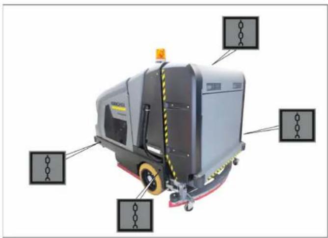
natural_image
Industrial cleaning machine with labeled components (no visible text or symbols)natural_image
Close-up of a vehicle's front grille and side bumper with a coiled tire, no visible text or symbols⚠ PRÉCAUTION
text_image
Labeled diagram of an electronic device showing numbered components including battery, wires, and connectorsATTENTION
text_image
1 2 2 CUBSBER⚠️ AVERTISSEMENT
natural_image
Close-up of a blue industrial engine bay with visible components and wiring (no text or symbols)1 Jauge d'huile
text_image
Technical diagram of industrial machinery with numbered labels pointing to components⚠AVERTISSEMENT
text_image
Labeled mechanical assembly diagram showing components numbered 1, 2, and 3 with arrows indicating movement or force direction.text_image
Labeled diagram of a mechanical or optical setup with numbered components, likely from an engineering or lab context.ATTENTION
text_image
Close-up of automotive engine components with numbered labels pointing to parts 1 and 2⚠AVERTISSEMENT
natural_image
Interior view of a vehicle engine bay with visible hoses and components (no text or symbols)1 Capot
natural_image
Close-up of a black robotic vehicle with yellow wheels and red safety railing, showing a curved cable or wire connection (no text or symbols visible)
natural_image
Mechanical assembly diagram showing a motor and wiring with labeled component B (no readable text or symbols)
natural_image
Close-up of a mechanical assembly with labeled component 'C' and wiring (no readable text or symbols beyond label)
natural_image
Close-up of a cleaning machine blade with visible mesh and wiring, no text or symbols presentnatural_image
Close-up of a mechanical gear assembly with labeled parts (1 and 2), no readable text or symbols beyond labels1 Balai latéral
2 Vis
text_image
Labeled diagram of a mechanical device showing components 1, 2, and 3 with an orange warning light.
text_image
Labeled diagram of a mechanical device showing components 1, 2, and 3 with visible wiring and components.text_image
Labeled diagram of a cleaning or cleaning machine with numbered componentsnatural_image
Interior view of a mechanical device with numbered components (1, 2, 3) and no visible text or symbols on the main structure.text_image
Technical diagram of a cleaning or maintenance vehicle with numbered components labeled 1, 2, and 3.text_image
Labeled diagram of a robotic device showing components 1, 2, and 3 with visible wiring and mounting hardware.natural_image
Close-up of a heat exchanger or cooling unit with visible cooling pipes and heat sinks (no text or symbols)⚠ AVERTISSEMENT
text_image
X173.1 X173.1 1 2 3 4
text_image
1 2 3 4 5 6 7 8 A B 9 10 11 12 13 14 15 162006/42/CE (+2009/127/CE)
2014/30/UE
2000/14/CE
2014/53/UE (TCU)
H. Jenner Chairman of the Board of Management

S. Reiser Director Regulatory Affairs & Certification
71364 Winnenden (Germany)
Tel.: +49 7195 14-0
Fax: +49 7195 14-2212
Winnenden, 2020/01/01
1 Indice
text_image
Labeled diagram of a vehicle's interior components with numbered parts, showing dashboard and control panel layout.1 Sedile di guida
2 Pedale del freno
3 Acceleratore
4 Tasto funzione
5 Volante
text_image
Labeled diagram of a mechanical device showing numbered components including switches, warning symbols, and industrial equipment.natural_image
Close-up of a car's front grille and side-mounted sensors, no visible text or symbolsnatural_image
Interior view of a vehicle engine bay with visible hoses, valves, and components (no text or symbols)text_image
Labeled interior view of a mechanical device with numbered components, showing internal compartments and components like gears and sensors.text_image
Labeled interior view of a vehicle's steering wheel and dashboard with numbered parts for identificationnatural_image
Close-up of an orange gas cylinder with a yellow connector and coiled tubing, no visible text or symbolsnatural_image
Interior view of a mechanical device with numbered components (1, 2, 3) and no visible text or symbols on the main structure.Indicazione
text_image
Industrial control panel with labeled components and warning symbolstext_image
Labeled diagram of a mechanical device with numbered components and control panelATTENZIONE
natural_image
Close-up of a mechanical device with three vertical metal switches and a red indicator light, no visible text or symbols.text_image
Labeled diagram of a cleaning or cleaning machine with numbered componentstext_image
Labeled diagram of a machine tool with numbered components and control panelATTENZIONE
text_image
Labeled diagram of a mobile industrial testing machine with numbered components and an inset showing internal components.PERICOLO
Rischio di lesioni!
natural_image
Close-up of a cleaning or cleaning machine component with labeled parts (1 and 2), no readable text or symbols beyond labels.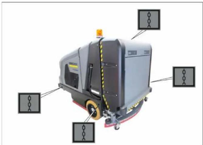
natural_image
Industrial cleaning machine with labeled components (no visible text or symbols)⚠AVVERTIMENTO
natural_image
Close-up of a vehicle's rear bumper with mesh grille and tire, no visible text or symbols⚠️ PRUDENZA
text_image
Labeled diagram of an electrical enclosure showing numbered components including battery, switch, and wiring.ATTENZIONE
natural_image
Close-up of a blue industrial engine bay with visible components and wiring (no text or symbols)text_image
Technical diagram of industrial machinery with numbered components and labeled parts⚠AVVERTIMENTO
text_image
Labeled mechanical assembly diagram showing components numbered 1, 2, and 3 with arrows indicating movement or force direction.text_image
Labeled diagram of a mechanical device with numbered components, showing components like lens, clamped unit, and optical components.ATTENZIONE
text_image
Labeled mechanical assembly diagram showing components with numbered parts and a magnified view of a cylindrical component.⚠AVVERTIMENTO
natural_image
Interior view of a vehicle engine bay with visible hoses, valves, and components (no text or symbols)1 Coperchio
natural_image
Close-up of a robotic car wheel with a red and black component, labeled 'A' with an arrow pointing to the wheel (no text or symbols on the vehicle itself)natural_image
Close-up of a mechanical assembly with labeled component B, showing components like wheels and wires (no readable text or symbols)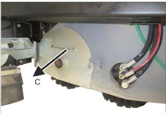
natural_image
Close-up of a vehicle's wheel assembly with visible wiring and components (no text or symbols)
natural_image
Close-up of a cleaning machine blade with visible brush and wiring, no text or symbols presentnatural_image
Close-up of a mechanical gear assembly with labeled parts (1 and 2), no readable text or symbols beyond labels1 Spazzole laterali
2 V i t i
text_image
Labeled diagram of a mechanical device showing components 1, 2, and 3 with an orange warning light.text_image
Labeled diagram of a mechanical device with numbered components, likely for assembly or testing purposes.text_image
Labeled diagram of a cleaning or cleaning machine with numbered componentsnatural_image
Interior view of a mechanical device with numbered components (1, 2, 3) and no visible text or symbols on the main structure.text_image
Labeled diagram of a robotic floor vehicle showing components 1, 2, and 3 with yellow safety markings.text_image
Labeled diagram of a robotic device showing components 1, 2, and 3 with visible wiring and mounting hardware.natural_image
Close-up of a heat exchanger or cooling unit with visible cooling pipes and heat sinks (no text or symbols)⚠ AVVERTIMENTO
text_image
X173.1 X173.1 1 2 3 4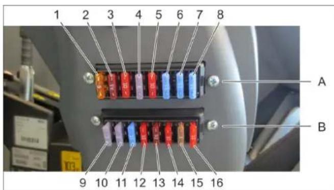
text_image
1 2 3 4 5 6 7 8 A B 9 10 11 12 13 14 15 162006/42/CE (+2009/127/CE)
2014/30/UE
2000/14/CE
2014/53/UE (TCU)
71364 Winnenden (Germany)
Tel.: +49 7195 14-0
Fax: +49 7195 14-2212
Winnenden, 2020/01/01
1 Inhoud
text_image
Labeled interior view of a vehicle's steering wheel and dashboard with numbered parts for identification1 Bestuurdersstoel
2 Rempedaal
3 Gaspedaal
4 Functieschakelaar
5 Stuurwiel
text_image
Industrial machine control panel with numbered labels pointing to various safety symbols and warning signsnatural_image
Close-up of a car's front grille and side-mounted lock, showing mesh texture and a labeled component (1), with no readable text or symbols beyond the label.Vrijloop (bypass) openen
Vrijloop (bypass) sluiten
natural_image
Interior view of a vehicle engine bay with visible hoses, springs, and components (no text or symbols)1 Afsluitdeksel
2 Koelmiddel-compensatievat
5.8 Tanken (dieselmotor)
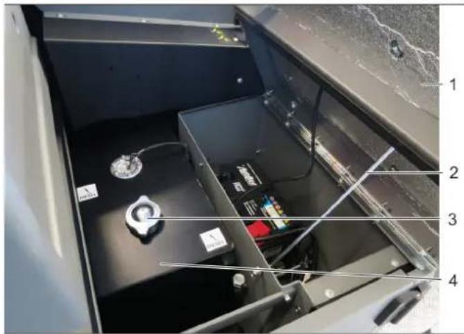
text_image
Labeled interior view of a mechanical device with numbered components and visible wiringGEVAAR
Ongevalgevaar!
text_image
Labeled interior view of a vehicle's steering wheel and dashboard with numbered parts for identification1 Bestuurdersstoel
2 Rempedaal
3 Gaspedaal
4 Functieschakelaar
5 Stuurwiel
natural_image
Close-up of an orange gas cylinder with a yellow valve inserted, showing internal components and a tool (no text or symbols visible)LET OP
natural_image
Interior view of a mechanical device with numbered components (1, 2, 3) and no visible text or symbols on the main structure.text_image
Industrial control panel with labeled components and warning symbols, showing switches and indicatorsLET OP
text_image
Labeled mechanical device diagram with numbered components and control buttons
natural_image
Close-up of a mechanical lever mechanism with four black-handled buttons and a digital display (no visible text or symbols)text_image
Labeled diagram of a cleaning or cleaning machine with numbered components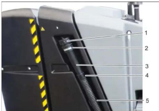
text_image
1 2 3 4 56.2.7 Schoonwatertank leegmaken
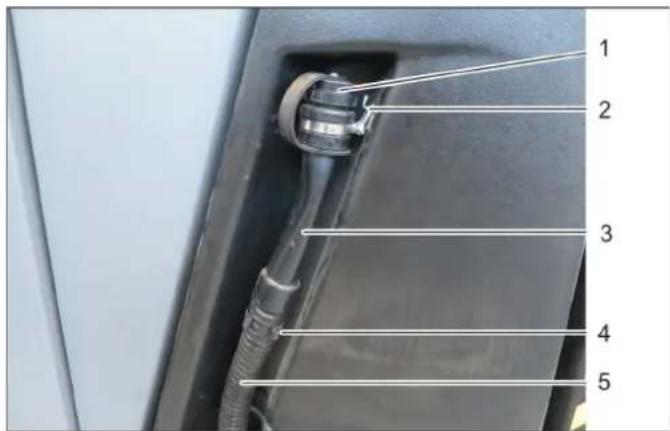
text_image
1 2 3 4 5⚠ WAARSCHUWING
→ Vuilwaterreservoir
LET OP
text_image
Labeled diagram of a machine tool with numbered components and control panelLET OP
text_image
Labeled diagram of a mobile industrial testing machine with numbered components and an inset showing internal components.GEVAAR
Verwondingsgevaar!
natural_image
Close-up of a cleaning or cleaning machine component with labeled parts (1 and 2), no readable text or symbols beyond labels.natural_image
Industrial cleaning machine with labeled components (no visible text or symbols)natural_image
Close-up of a vehicle's rear panel showing grille, tire, and handle (no text or symbols visible)⚠️ VOORZICHTIG
Beschadigingsgevaar!
text_image
Labeled diagram of an electrical enclosure or battery pack with numbered components from 1 to 5LET OP
natural_image
Close-up of a blue automotive engine bay with visible components and wiring (no text or symbols)text_image
Technical diagram of industrial machinery with numbered components and labeled parts⚠ WAARSCHUWING
Verbrandingsgevaar!
text_image
Technical diagram showing mechanical components with numbered labels pointing to specific partstext_image
Labeled diagram of a mechanical or optical setup with numbered components, likely from an engineering or lab context.text_image
Close-up of automotive engine components with numbered labels pointing to parts 1 and 2LET OP
natural_image
Interior view of a vehicle engine bay with hoses and components (no visible text or symbols)1 Deksel
2 Koelmiddel-compensatievat
natural_image
Close-up of a robotic car wheel with a yellow tire and red safety railing, showing a curved cable or sensor (no text or symbols visible)
natural_image
Close-up of a mechanical assembly with labeled component B, showing wiring and components without any readable text or symbols.
natural_image
Close-up of a mechanical assembly with visible wiring and components (no text or symbols)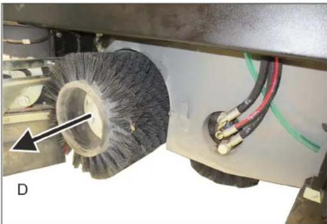
natural_image
Close-up of a cleaning brush head with visible wires and components, no text or symbols present9.6.1 Veegspoor (borstelaandrukkeracht) instellen
text_image
A 5-6 cm A 5-6 cmnatural_image
Close-up of a mechanical gear assembly with labeled parts (1 and 2), no readable text or symbols beyond labels1 Zijbezem
2 Schroeven
text_image
Labeled diagram of a laboratory instrument with numbered components and orange warning light indicatortext_image
Labeled diagram of a mechanical device with numbered components, likely for assembly or testing purposes.9.8.2 Vlak harmonicafilter reinigen / vervangen
text_image
1 2 3 49.8.3 Voertuig reinigen
1 Moeren (4x)
2 Rail filterreiniging
text_image
Labeled diagram of a cleaning or cleaning machine with numbered components1 Aftapslang vuil water
2 Vuilwaterreservoir
3 Sensor
natural_image
Interior view of a mechanical device with numbered components (1, 2, 3) and no visible text or symbols on the main structure.text_image
Labeled diagram of a robotic floor vehicle showing components 1, 2, and 3 with yellow safety markings.1 Schoonwaterreservoir
2 Deksel schoonwatertank
3 Aanduiding vulstand
4 Aftapslang schoon water
text_image
Labeled diagram of a robotic device showing components 1, 2, and 3 with visible parts and wiring.9.8.8 Waterfilter reinigen.

text_image
1 2 3natural_image
Close-up of a heat exchanger or cooling unit with visible cooling pipes and heat sinks (no text or symbols)⚠ WAARSCHUWING
text_image
X173.1 X173.1 1 2 3 4
text_image
1 2 3 4 5 6 7 8 A B 9 10 11 12 13 14 15 1671364 Winnenden (Germany)
Tel.: +49 7195 14-0
Fax: +49 7195 14-2212
Winnenden, 2020/01/01
text_image
Labeled diagram of a vehicle's steering wheel and dashboard with numbered parts for identificationtext_image
Labeled diagram of industrial equipment showing numbered components including warning signs, sensors, and a valve mechanism.natural_image
Close-up of a car's front grille and side-mounted tire, showing no text or symbols on the main subject.natural_image
Interior view of a vehicle engine bay with visible hoses, valves, and components (no text or symbols)1 Tapa de cierre
2 Recipiente compensador de refrigerante
text_image
Labeled interior view of a mechanical device with numbered components, showing internal compartments and components like gears and sensors.⚠️ PELIGRO
text_image
Labeled diagram of a vehicle's interior dashboard and steering wheel, showing numbered parts from 1 to 12.natural_image
Close-up of an orange gas cylinder with a yellow connector and coiled tubing, no visible text or symbols6.1.5 Arrancar el motor
CUIDADO
natural_image
Close-up of a mechanical device with numbered annotations pointing to components (no readable text or symbols)6.2.2 Detergente recomendado
ADVERTENCIA
text_image
Industrial control panel with labeled components and warning symbolstext_image
Labeled diagram of a mechanical device with numbered components and control knobs
natural_image
Industrial control panel with four vertical sliders and a red indicator light, no visible text or symbolsCUIDADO
text_image
Labeled diagram of a cleaning or cleaning machine with numbered components
text_image
1 2 3 4 5text_image
Labeled diagram of a mechanical device with numbered components and control knobsCUIDADO
text_image
Labeled diagram of a robotic device with numbered components and an inset showing a control panel with warning symbols.natural_image
Close-up of a small industrial cleaning or cleaning machine component with labeled parts (1 and 2), no visible text or symbols on the main body.natural_image
Industrial cleaning machine with labeled components (no visible text or symbols)natural_image
Close-up of a car's front grille and side-mounted tire, showing no text or symbols on the main subject.△PRECAUCIÓN
text_image
Labeled diagram of an electronic device interior with numbered components for identificationCUIDADO
natural_image
Close-up of a blue automotive engine bay with visible components and wiring (no text or symbols)text_image
Industrial machinery diagram with numbered components and labeled parts, showing blue pipes, hoses, and mechanical parts.ADVERTENCIA
text_image
Labeled mechanical assembly diagram showing a component with numbered parts and directional arrows indicating movement or force.text_image
Labeled diagram of a mechanical device with numbered components, showing components like lens, optical lens, and control panel.9.5.7 Sustituir el filtro de aceite hidráulico
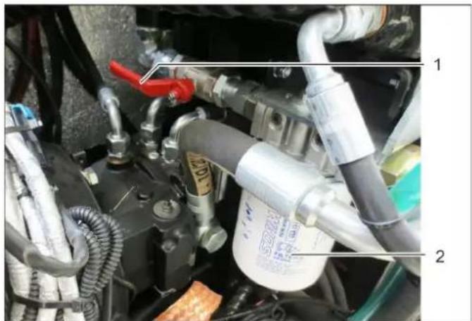
text_image
Labeled mechanical assembly diagram showing components with numbered parts and visible pipes and labelsCUIDADO
text_image
Labeled mechanical assembly diagram showing engine components with numbered annotationsnatural_image
Close-up of a robotic car's wheel and side-mounted sensors, showing red and black components with a curved cable labeled 'A' (no text or symbols on the main subject)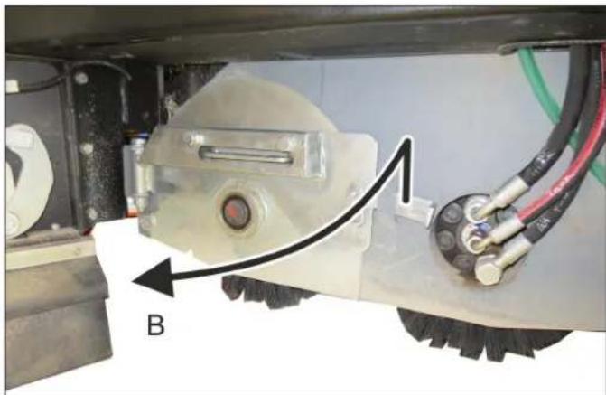
natural_image
Mechanical assembly diagram showing a motor and wheel with labeled component B (no text or symbols beyond label)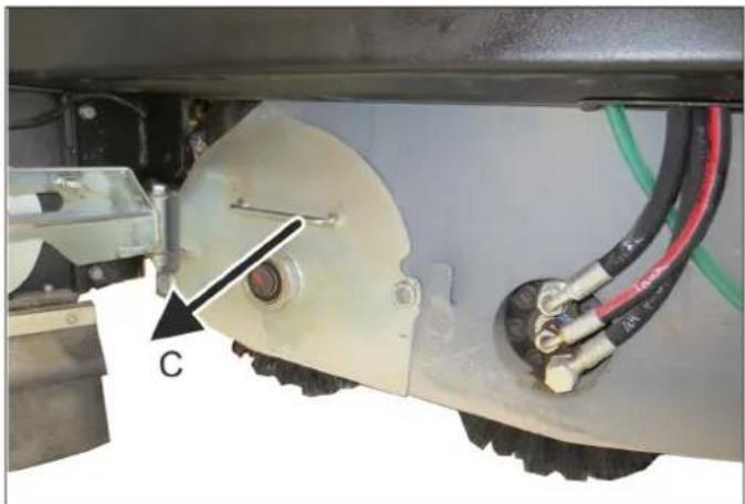
natural_image
Close-up of a mechanical assembly with visible components and wiring (no text or symbols)
natural_image
Close-up of a cleaning machine brush head with visible wire and wiring, no text or symbols presentnatural_image
Close-up of a mechanical gear assembly with labeled parts (1 and 2), no readable text or symbols beyond labels1 Escoba lateral
2 Tornillos
text_image
Labeled diagram of a laboratory instrument with numbered parts, including a warning light and control panel.
text_image
Labeled diagram of a mechanical device showing components 1, 2, and 3 with visible wiring and components.text_image
Labeled diagram of a cleaning or cleaning machine with numbered componentsnatural_image
Interior view of a mechanical device with numbered components (1, 2, 3) and no visible text or symbols on the main structure.text_image
Labeled diagram of a robotic floor vehicle showing components 1, 2, and 3 with yellow safety markings.text_image
Labeled diagram of a robotic device showing components 1, 2, and 3 with visible wiring and mounting hardware.natural_image
Close-up of a heat exchanger or cooling unit with visible cooling pipes and heat sinks (no text or symbols)ADVERTENCIA
text_image
X173.1 X173.1 1 2 3 4
text_image
1 2 3 4 5 6 7 8 A B 9 10 11 12 13 14 15 162006/42/CE (+2009/127/CE)
2014/30/UE
2000/14/CE
2014/53/UE (TCU)
71364 Winnenden (Germany)
Tel.: +49 7195 14-0
Fax: +49 7195 14-2212
Winnenden, 2020/01/01
1 Índice
text_image
Labeled diagram of a vehicle's interior components with numbered parts, showing dashboard and control panel layout.text_image
Industrial machine control panel with numbered labels pointing to various safety symbols and warning signsnatural_image
Close-up of a car's front grille and side rear bumper with a coiled tire, no visible text or symbolsnatural_image
Interior view of a vehicle engine bay with visible hoses, valves, and components (no text or symbols)1 Tampa de fecho
text_image
Labeled interior view of a mechanical or electronic device with numbered componentsPERIGO
Perigo de acidente!
text_image
Labeled diagram of a vehicle dashboard with numbered parts and control buttons1 Banco do condutor
2 Pedal do travão
3 Pedal do acelerador
4 Interruptor de funcionamento
5 Volante
natural_image
Close-up of an orange gas cylinder with a yellow valve inserted, mounted on a black base (no visible text or symbols)ADVERTÊNCIA
natural_image
Interior view of a mechanical device with numbered components (1, 2, 3) and no visible text or symbols on the main structure.6.2.2 Detergentes recomendados
ATENÇÃO
Perigo de danos!
text_image
Labeled diagram of a machine tool with numbered components and control panel
natural_image
Industrial control panel with four vertical sliders and a red indicator light, no visible text or symbolstext_image
Labeled diagram of a cleaning or cleaning machine with numbered components
text_image
1 2 3 4 5text_image
Labeled diagram of a machine tool with numbered parts and control panelADVERTÊNCIA
text_image
Labeled diagram of a mobile industrial testing machine with numbered components and an inset showing internal components.PERIGO
Perigo de lesões!
natural_image
Close-up of a cleaning or cleaning machine component with labeled parts (1 and 2), showing no readable text or symbols beyond labels.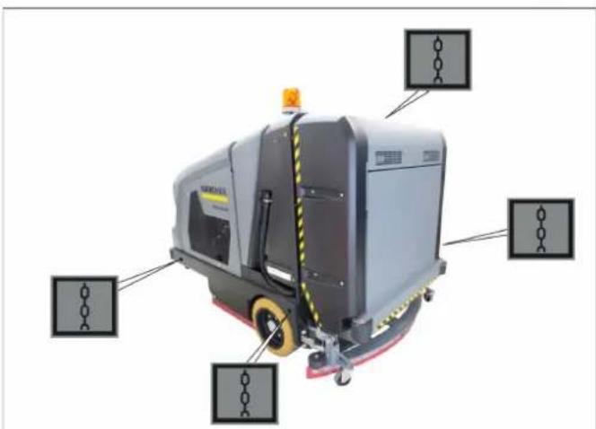
natural_image
Industrial cleaning machine with labeled components (no visible text or symbols)1 Varredora de vassoura lateral
natural_image
Close-up of a vehicle's rear bumper with mesh grille and tire, no visible text or symbolsCUIDADO
Perigo de danos!
text_image
Labeled diagram of an electronic device showing numbered components including battery, wires, and connectorsADVERTÊNCIA
natural_image
Close-up of a blue industrial engine bay with visible components and wiring (no text or symbols)text_image
Technical diagram of industrial machinery with numbered labels pointing to componentsATENÇÃO
Perigo de queimaduras!
text_image
Labeled mechanical assembly diagram showing components numbered 1, 2, and 3 with arrows indicating movement or force direction.text_image
Labeled diagram of a mechanical or optical setup with numbered componentsADVERTÊNCIA
text_image
Labeled mechanical assembly diagram showing components with numbered parts and a magnified view of a cylindrical component.ATENÇÃO
Perigo de queimaduras!
natural_image
Interior view of a vehicle engine bay with hoses and components (no visible text or symbols)ATENÇÃO
Perigo de queimaduras!
text_image
Technical diagram showing engine components with numbered parts and labeled parts1 Bloqueio
natural_image
Close-up of a black and yellow robotic vehicle's wheel with red and white components, showing a curved cable or wire connection (no text or symbols visible)
natural_image
Close-up of a mechanical assembly with labeled component B, showing components like rollers and wires (no readable text or symbols)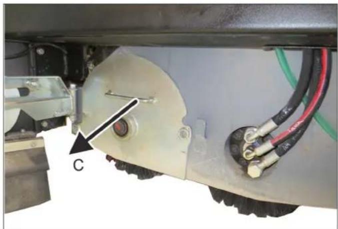
natural_image
Close-up of a mechanical assembly with visible components and wiring (no text or symbols)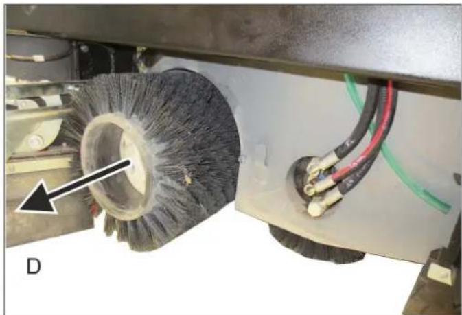
natural_image
Close-up of a cleaning brush head with visible wiring and components, no text or symbols presentnatural_image
Close-up of a mechanical gear assembly with labeled parts (1 and 2), no readable text or symbols beyond labels1 Vassoura lateral
2 Parafusos
text_image
Labeled diagram of a laboratory instrument with numbered components and orange warning light indicatortext_image
Labeled diagram of a mechanical device showing components 1, 2, and 3 with visible wiring and components.9.8.2 Limpar/substituir o filtro de pregas

text_image
1 2 3 4text_image
Labeled diagram of a cleaning or cleaning machine with numbered componentsnatural_image
Close-up of a mechanical device with numbered annotations pointing to components (no readable text or symbols)text_image
Labeled diagram of a robotic cleaning or maintenance vehicle showing numbered components: 1, 2, and 3.text_image
Labeled diagram of a robotic device showing components 1, 2, and 3 with visible parts and wiring.natural_image
Close-up of a heat exchanger or cooling unit with visible cooling pipes and heat sinks (no text or symbols)⚠️ ATENÇÃO
Perigo de ferimentos e de danos!
text_image
X173.1 X173.1 1 2 3 4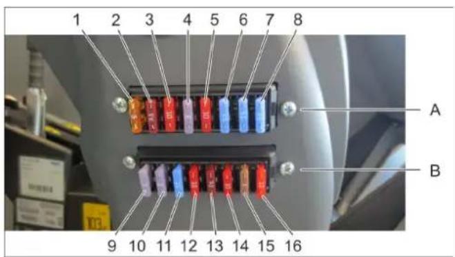
text_image
1 2 3 4 5 6 7 8 A B 9 10 11 12 13 14 15 162006/42/CE (+2009/127/CE)
2014/30/UE
2000/14/CE
2014/53/UE (TCU)
Alfred Kärcher SE & Co. KG Alfred-Kärcher-Straße 28-40 71364 Winnenden (Germany)
Tel.: +49 7195 14-0
Fax: +49 7195 14-2212
Winnenden, 2020/01/01
text_image
Labeled interior view of a vehicle's steering wheel and dashboard with numbered parts, showing control buttons and wiring.text_image
Industrial machine control panel with numbered labels pointing to various safety symbols and warning signsnatural_image
Close-up of a car's front grille and side-mounted tire, showing a small circular component attached to the grille (no text or symbols visible)natural_image
Interior view of a vehicle engine bay with visible hoses, pipes, and structural components (no text or symbols)1 Καπάκι σφράγισης
text_image
Industrial machine control panel with warning icons and labels, showing a hand operating a tool near a mechanical component.ΔKINDYNOΣ
text_image
Labeled interior view of a mechanical device with numbered components and visible wiring⚠️ KINΔΥΝΟΣ
Κίνδυνος έκρηξης!
text_image
Labeled diagram of a vehicle's interior components with numbered parts for identificationnatural_image
Close-up of an orange gas cylinder component with a yellow connector and coiled tubing, mounted on a black base (no visible text or symbols)natural_image
Interior view of a laboratory instrument with labeled parts (1, 2, 3), no visible text or symbols beyond labelstext_image
Industrial control panel with labeled components and warning symbolsΠΡΟΣΟΧΗ
text_image
Labeled diagram of a laboratory instrument with numbered parts for identification
natural_image
Close-up of a mechanical control panel with four black-handled switches and a red indicator light (no visible text or symbols)text_image
Labeled diagram of a cleaning or cleaning machine with numbered components
text_image
1 2 3 4 5text_image
Labeled diagram of a machine tool with numbered components and control panelΠΡΟΣΟΧΗ
text_image
Labeled diagram of a mechanical device with numbered components and an inset showing a control panel with warning signs.⚠️KINDYNOΣ
natural_image
Close-up of a cleaning or cleaning machine component with labeled parts (1 and 2), no visible text or symbols beyond labels.
natural_image
Industrial cleaning machine with labeled components (no visible text or symbols)natural_image
Close-up of a car's front grille and side-mounted tire, showing a coiled cable attachment (no text or symbols visible)text_image
Labeled diagram of an electronic device showing numbered components including battery, wires, and connectorstext_image
Close-up of a blue automotive engine with numbered annotations pointing to components⚠️KINDYNOΣ
text_image
Technical diagram of industrial machinery with numbered labels pointing to components⚠️ ΠΡΟΕΙΔΟΠΟΙΗΣΗ
text_image
Labeled mechanical assembly diagram showing components numbered 1, 2, and 3 with a central component and directional arrowtext_image
Labeled diagram of an optical or mechanical setup with numbered componentsΠΡΟΣΟΧΗ
text_image
Close-up of automotive engine components with numbered labels pointing to parts 1 and 2ΔΠΡΟΕΙΔΟΠΟΙΗΣΗ
natural_image
Interior view of a vehicle engine bay with visible hoses and components (no text or symbols)1 Κάλυμμα
text_image
Technical diagram showing engine components with numbered parts and labeled parts1 A σ φ ά λι σ η
natural_image
Close-up of a robotic car's wheel and side panel with a red base and black handle, showing a curved cable and labeled point A (no text or symbols on the main subject)
natural_image
Close-up of a mechanical cleaning or cleaning device with visible components and wiring (no text or symbols)
natural_image
Close-up of a mechanical component with labeled parts (C) and wiring, no readable text or symbols beyond the label.
natural_image
Close-up of a cleaning brush head with visible brush and wiring, no text or symbols presentnatural_image
Close-up of a mechanical gear assembly with numbered components (1 and 2), no visible text or symbols beyond labels9.8 Καθαρισμός
1 Πλευρική σκούπα
2 B í δ ε ζ
text_image
Labeled diagram of a laboratory instrument with numbered components and orange warning light indicator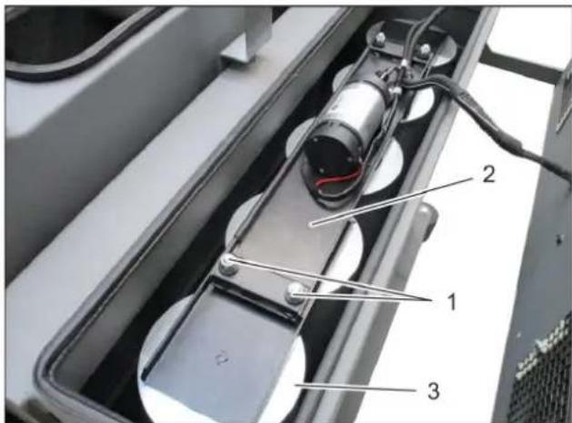
text_image
Labeled diagram of a mechanical device showing components 1, 2, and 3 with visible wiring and components.text_image
Labeled diagram of a cleaning or cleaning machine with numbered componentsnatural_image
Interior view of a mechanical device with numbered components (1, 2, 3) and no visible text or symbols on the main structure.text_image
Labeled diagram of a robotic vehicle showing components 1, 2, and 3 with yellow safety markingstext_image
Labeled diagram of a robotic device showing components 1, 2, and 3 with visible parts and wiring.natural_image
Close-up of a heat exchanger or cooling unit with visible cooling pipes and heat dissipation (no text or symbols)⚠️ ΠΡΟΕΙΔΟΠΟΙΗΣΗ
text_image
X173.1 X173.1 1 2 3 4
text_image
1 2 3 4 5 6 7 8 A B 9 10 11 12 13 14 15 16Chairman of the Board of Management

S. Reiser
Director Regulatory Affairs & Certification
71364 Winnenden (Germany)
Tel.: +49 7195 14-0
Fax: +49 7195 14-2212
Winnenden, 2020/01/01

natural_image
Black silhouette of a hand giving a thumbs-up gesture (no text or symbols)THANK YOU!
MERCI! DANKE! iGRACIAS!
Registrieren Sie Ihr Produkt und profitieren Sie von vielen Vorteilen. Register your product and benefit from many advantages. Enregistrez votre produit et bénéficier de nombreux avantages. Registre su producto y aproveche de muchas ventajas.
www.kaercher.com/welcome

Bewerten Sie Ihr Produkt und sagen Sie uns Ihre Meinung. Rate your product and tell us your opinion. Évaluer votre produit et dites-nous votre opinion. Reseñe su producto y díganos su opinión.

natural_image
Icon showing a gear and wrench inside a square frame (no text or symbols)www.kaercher.com/dealersearch
Alfred Kärcher SE & Co. KG
Alfred-Kärcher-Str. 28-40
71364 Winnenden (Germany)