WRH 1200 Classic - Pressure washer Kärcher - Free user manual and instructions
Find the device manual for free WRH 1200 Classic Kärcher in PDF.

User questions about WRH 1200 Classic Kärcher
0 question about this device. Answer the ones you know or ask your own.
Ask a new question about this device
Download the instructions for your Pressure washer in PDF format for free! Find your manual WRH 1200 Classic - Kärcher and take your electronic device back in hand. On this page are published all the documents necessary for the use of your device. WRH 1200 Classic by Kärcher.
USER MANUAL WRH 1200 Classic Kärcher
natural_image
Technical line drawing of a gas cylinder connected to a vertical panel and piping system (no text or symbols)Deutsch 3
English 10
Français 17
Italiano 24
Nederlands 32
Español 39
Português 46
Dansk 54
Norsk 61
Svenska 68
Suomi 75
Ελληνικά 82
Türkçe 90
Русский 97
Magyar 106
Čeština 113
Slovenščina 120
Polski 127
Românește 134
Slovenčina 142
Hrvatski 149
Srpski 156
Български 163
Eesti 171
Latviešu 178
Lietuviškai 185
Українська 192
text_image
Technical diagram of a gas pump system with numbered components and labeled parts1 Spannhebel
natural_image
Technical line drawing of a mechanical component with no visible text or symbolstext_image
Technical schematic diagram of a gas or fluid system with numbered components and directional flow indicatorsnatural_image
Close-up of a transparent plastic container with internal layers, placed on a grid surface (no text or symbols visible)natural_image
Close-up of a transparent cylindrical container with a circular top, placed on a grid surface (no visible text or symbols)text_image
Technical diagram of a mechanical device with numbered components and cross-sectional views1 Mutter
2 Spannhebel
text_image
Technical diagram of a mechanical device with labeled components and directional arrows indicating flow or movement.1 Nutenstein
natural_image
Cross-sectional diagram of a mechanical component with internal structure and directional arrows (no text or symbols)natural_image
Technical line drawing of a mechanical assembly with no visible text or symbols
Chairman of the Board of Management
S. Reiser
Director Regulatory Affairs & Certification
71364 Winnenden (Germany)
Tel.: +49 7195 14-0
Fax: +49 7195 14-2212
Winnenden, 2018/10/01
Please read and comply with these original instructions prior
to the initial operation of your appliance and store them for later use or subsequent owners.
Contents
Contents ..... EN .. 1
About this Operations Manual EN .. 1
Environmental protection .. EN .. 1
Warranty ..... EN .. 1
Symbols in the operating instructions ..... EN .. 1
Proper use ..... EN .. 1
Safety instructions ..... EN .. 1
Device elements ..... EN .. 2
Operation ..... EN .. 2
Function ..... EN .. 3
Technical specifications ... EN .. 3
Transport..... EN .. 3
Storing the device..... EN .. 3
Maintenance and care .... EN .. 4
Troubleshooting ..... EN .. 6
Accessories ..... EN .. 7
EU Declaration of Conformity EN .. 7
Installing the unit (only for experts). . . . . . . . . . . . . . . . . EN .. 7
About this Operations Manual
Target group for these instructions
– All users: Users include trained auxiliary personnel, operators and experts.
- Experts: Experts are individuals, who are, according to their professional education, able to install the equipment and to operate the same.
Definitions
Fresh water
Tap water
Waste water
Dirty water discharged from the high pressure cleaner
Processed water
Water prepared by the system for reuse in the washing programmes (preliminary washing, high pressure cleaning) with a high-pressure cleaner.
Environmental protection

The packaging materials are recyclable. Please do not throw packaging in the domestic waste but pass it on for recycling.
Old units contain valuable recyclable materials. Batteries, oil and similar substances may not be released into the environment. Therefore please dispose of old units through suitable collection systems.
Notes about the ingredients (REACH)
You will find current information about the ingredients at:
www.kaercher.com/REACH
Warranty
The warranty terms published by our competent sales company are applicable in each country. We will repair potential failures of your appliance within the warranty period free of charge, provided that such failure is caused by faulty material or defects in fabrication. In the event of a warranty claim please contact your dealer or the nearest authorized Customer Service center. Please submit the proof of purchase.
Symbols in the operating instructions
⚠️DANGER
Immediate danger that can cause severe injury or even death.
⚠ WARNING
Possible hazardous situation that could lead to severe injury or even death.
CAUTION
Possible hazardous situation that could lead to mild injury to persons or damage to property.
Proper use
The system cleans dirt water discharged from vehicle cleaning and provides processed water to the high-pressure cleaner (max. 1,200 litres per hour). The used water can only be used for cleaning programmes (for e.g. preliminary washing, high pressure cleaning). Processed water is not suitable for use as rinsing water or for applying drying aid or some other such purpose.
Cleaning is done by:
- Separating heavy parts that easily settle down in the gravel filter.
If the water level in the pump basin exceeds a certain height, the solenoid valve opens and water is routed to the sewer system via the active carbon filter.
Pre-requisites for smooth functioning:
- Basin system according to the water flow diagram shown in the "Function" chapter.
– Maximum water quantity 2,000 l/h
– Minimum water quantity 1,200 l/h
- The wastewater in the system inlet contains a max. of 30 mg of oil per litre of water.
– The company supplied oil separator must be properly maintained.
Safety instructions
General
To avoid danger to persons, animals and property before the first operation of the system, read:
- this operating instructions manual, especially the safety instructions contained therein
– the enclosed "Safety instructions for waste water treatment plants"
– the respective national statutes of the legislator
All individuals, who are involved, in the installation, the operation, the maintenance and service of this equipment, must be
– have the requisite qualifications,
– know and observe the "Safety instructions for waste water treatment plants",
– know and have read this operations manuals,
– know and follow the corresponding regulations.
The appliance may only be used by persons who have been instructed in handling the appliance or have proven qualification and expertise in operating the appliance or have been explicitly assigned the task of handling the appliance.
This appliance is not intended for use by persons with reduced physical, sensory or mental capabilities.
The appliance must not be operated by children or persons who have not been instructed accordingly.
DANGER
Do not drink the processed water - health hazard. The cleaned waste water is not of a potable quality. It still contains some residues of dirt and detergents.
⚠️DANGER
text_image
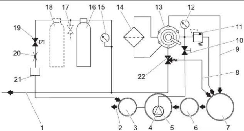
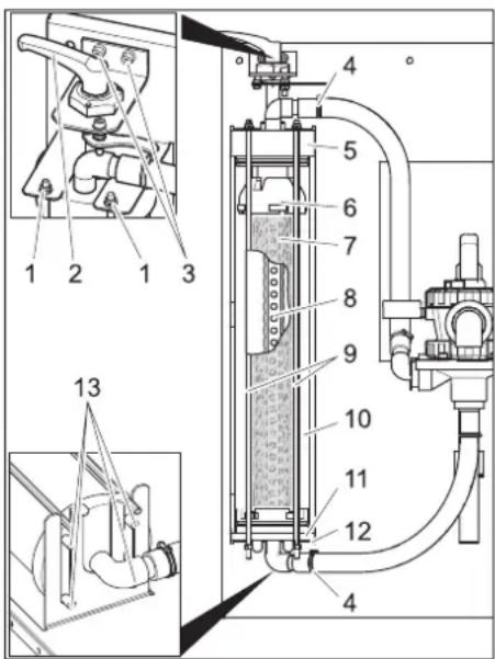
Technical diagram of a gas pump system with numbered components and labeled parts1 Tension lever
2 Unlocking lever
3 Filament filter
4 Multi-channel valve
5 Manometer at the filter inlet
6 Overflow valve
7 Throttle valve **)
8 Manometer active carbon filter
9 Active carbon filter
10 Hose coupling at output of active carbon filter
11 Hose coupling at input of active carbon filter
12 Safety valve
13 Aperture
14 Filtrate hose
15 Switch solenoid
16 2. Active carbon filter **)
17 Test tap **)
18 Solenoid valve
A To the sludge collector
B to collect sludge (rinse back)
C from the immersion pump
D To the sludge collector (excessive pressure)
E to the high-pressure cleaner / processed water tank (filling)
F To the drainage system
**) Option
Operation
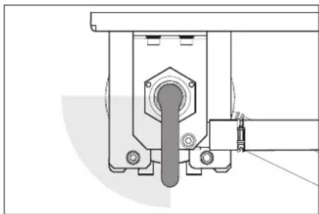
Adjust the filter pre-tension
Proceed as follows to subsequently change the filter tension:
→ Turn the tension lever to the left until the lever reaches the stop. Then attach it with the unlocking lever.
Filter operations
natural_image
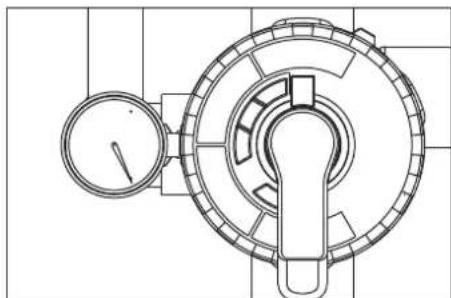
Technical line drawing of a mechanical component with no visible text or symbols→ Turn the lever of the multi-channel valve in "FILTRATION" position.
NOTICE
After longer idling times it takes a lot of effort to activate the multi-channel valve.
→ Check filter pre-tension.
→ Start the pump in the building.
Backwash
NOTICE
During normal operations, you must backwash the filter at least once daily. The system does not release any processed water during the back-rinsing process..
During backwash, the dirt collected in the filament filter is removed. To do this, the filament filter is rinsed in the reverse direction. The rinsed dirt is routed to the sludge collector of the recycling system.
→ Start the pump in the building.
⚠ WARNING
The max. permissible flow volume during return rinse is 2,000 l/h. Adjust flow volume on throttle valve if necessary (order no.) 4.640-230.0).
→ Turn the lever of the multi-channel valve in "RÜCKSPÜLEN/BACKWASH" position.
→ Loosen the filament filter by turning the tension lever in the anti-clockwise direction.
→ Wait for 30 seconds.
→ Tighten the filament filter and loosen it immediately.
→ Repeat ten times this process of waiting for 10 minutes - tightening - loosening.
→ Reset the filter pre-tension.
→ Turn the lever of the multi-channel valve in "ERSTFILTRAT/RINSE" position.
→ Wait 2 minutes
→ Turn the lever of the multi-channel valve in "FILTRATION" position.
Processed water circulation
If the high-pressure cleaner or the washing system does not use up the water, the processed water is circulated to avoid foul odour.
NOTICE
The immersion pump can be periodically switched on/off during non-operating hours (for e.g. at night, over the week-end) to lower the operating hours. For this you can connect the immersion pump via a timer to the power supply.
Maximum interval increment: 1 hour.
Frost protection
The plant must be operated in frost-free rooms. During frost, put the system out of operation and remove all traces of water:
→ Pull out the hoses.
→ Let the system dry-run.
Shutdown
→ Switch off the building pump.
→ If there is risk of frosting, then any existing water traces must be removed (see section "Anti-freezing").
Function
Flow pattern
text_image
Technical schematic diagram of a gas or fluid system with numbered components and directional flow indicators1 To the processed water tank/ high-pressure cleaner
2 to drainage system *)
3 Control shaft *)
4 Immersion pump *)
5 Pump basin of the recycling system *)
6 Separation system (EN 858) *)
7 Sludge collection of the recycling system *)
8 Circulation (to sludge collector)
9 Backwash pipe
10 Throttle valve
11 Safety valve
12 Manometer at the filter inlet
13 Multi-channel valve
14 Filament filter
15 Manometer active carbon filter
16 Active carbon filter
17 Test tap **)
18 2. Active carbon filter **)
19 Solenoid valve
20 Restrictor
21 Filtrate hose
22 Overflow valve
*) on building side
**) Option
Functional description
The following section describes the flow-path of the water in different positions of the multi-channel valve.
FILTRATION
In filter operations, the water flows via
- Immersion pump
- Multi-channel valve in "FILTRATION" position
- Filter (flow direction of filtering)
- To the high-pressure cleaner/processed water tank
RÜCKSPÜLEN/BACKWASH
During backwash, the water flows via
- Immersion pump
- Multi-channel valve in position RÜCK-SPÜLEN/BACKWASH"
- Filter (against flow direction of filtering)
- To the sludge collector
ERSTFILTRAT/RINSE
During final rinse the water flows via:
- Immersion pump
- Multi-channel valve in position ERST-FILTRAT/RINSE
– Filter (flow direction of filtering)
- To the sludge collector
UMWÄLZUNG/RECIRCULATION
This position is not required for operating the system.
Function of active carbon filter
If the water level in the pump basin exceeds a certain height, the solenoid valve opens and water is routed to the sewer system via the active carbon filter.
Technical specifications
| Voltage V 230 | ||
| Frequency Hz 50 | ||
| Power W 12 | ||
| Pressure (min.) MPa | (bar) | 0,2(2) |
| Pressure (max.) MPa | (bar) | 0,35(3,5) |
| Filter capacity l/h 1200 | ||
| Waste water volume | l/d 550 | |
| Content of active carbon filter | l | 28 |
| Width | mm | 1000 |
| Depth | mm | 480 |
| Height | mm | 1600 |
| Weight | kg 110 |
Immersion pump requirements (building-side)
| Pressure (min.) | MPa(bar) | 0,2(2) |
| Pressure (max.) | MPa(bar) | 0,35(3,5) |
| Minimum flow rate at 0.2 MPa (2 bar) | l/h 120 | 0 |
| Max. flow rate | l/h 200 | 0 |
- Suitable for dirt water
- Suitable for continuous operations
- With protection against dry-run
NOTICE
Pumps with excessive performance can be throttled via the throttle valve.
Transport
△CAUTION
Risk of injury and damage! Observe the weight of the appliance when you transport it.
In der Anlage enthaltenes Restwasser muss vor dem Transport entfernt werden. When transporting in vehicles, secure the appliance according to the guidelines from slipping and tipping over.
Storing the device
△CAUTION
Risk of injury and damage! Note the weight of the appliance in case of storage.
Store the appliance in a frost free area.
Maintenance and care
Maintenance instructions
The bases of a safe operating of the equipment is thr regularly maintenance according to the following maintenance plan. Use only original parts of the manufacturer or part suggested by him, such as
- parts and wearing parts,
- accessories parts,
– operating materials, - cleaning agents.
⚠️DANGER
Risk of accident while working on the unit. During all tasks
First switch-on in voltage-less state, switch off the emergency stop switch in the building and secure it against being switched on again.
→ Shut off water supply.
→ Switch off the immersion pump in the building.
Who may perform maintenance?
- operator
Performances containing the notice "operator" may only be performed by instructed individuals, who are able to operate and service high pressure equipment.
- Maintenance
Performances with the notice "maintenance" may only be performed by the Kärcher- Maintenance-Mechanics.
Maintenance contract
In order to guarantee a reliable operation of the equipment, we success, you signed a maintenance agreement. Please refer to your local Kärcher service department.
Maintenance schedule
| Time Activity Assembly affected | Performance By whom | |||
| daily Back-wash | Filament filter Run bachwash Operator | |||
| weekly Clean the filter | Drain at washing place | Clean the dirt collection basket in the floor. Operator | ||
| opinion Detergent concentration in processed water | Reduce the detergent dosing at the detergent dispenser if there is foam formation. | Operator | ||
| Active carbon filter | Set the switch of the solenoid to "1" with the submersion pump running. Nominal value 25...30 l/h = 0.4...0.5 l/min. With lower flow, clean the shutter (see "Clean shutter"). | Operator | ||
| Set the switch of the solenoid to "1" with the submersion pump running. Take water sample at the test tap and check for foaming (see "Testing the active carbon filter").If foaming is observed, replace the active carbon (see "Replace active carbon").⚠WARNINGIf the active carbon filter is not checked once a week, oil or tensid containing water can be discharged into the sewer system. This can lead to consequences on the part of the authorities. In this case, there are no warranty claims accepted by KÄRCHER. | Operator | |||
| monthly opinion Sludge | collection, pump basin | After sludge has been collected, there should be no sludge in any of the basins. The sludge in the sludge collector should be maximum 1 m in height. Check sludge level; pump out and dispose off the sludge according to the local regulations, if required. | Operator | |
| opinion | Float switch | Check whether the float switch in the pump basin is freely movable. | ||
| actuate | Safety valve | Unscrew the knurled screw of the safety valve with the submersion pump running - water will escape. (The knurled screw cannot be removed completely. Screw in the knurled screw. | ||
| empty, clean | Processed water tank (if available) | Empty, clean, rinse and refill. | ||
| Half-year-ly (if required) | Change water, clean the basins | Sludge collection, oil separator, pump basin | Empty the basins, remove sludge completely and fill the basin with fresh water. Store the waste disposal documents. | Operator/ Disposal agency |
| annual | Exchange filter | Filter inlay | Replace filter inlay of the filament filter. | Operator/ Customer Service |
Clean the shutter
→ Mark the flow direction on the shutter.
→ Remove the shutter.
→ Clean the shutter opening with a needle or a thin wire.
→ Install the shutter while observing the flow direction.
→ Set the switch of the solenoid to "1" with the submersion pump running and check the flow.
Check active carbon filter
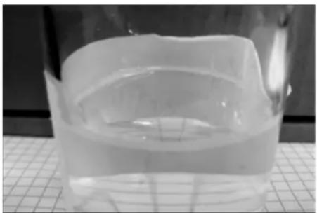
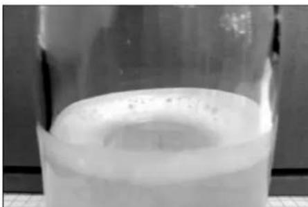
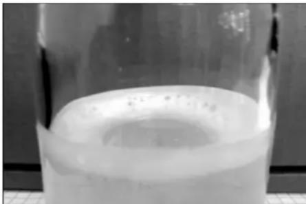
→ Fill the glass bottle halfway with a water sample after the active carbon filter and close it.
→ Shake the glass bottle vigorously for about 5 seconds.
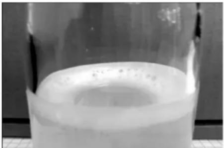
If there is a closed foam cover, which has not disintegrated after 40 seconds, the fill of the active carbon filter must be replaced.
natural_image
Close-up of a transparent plastic container with liquid, placed on a grid surface (no text or symbols visible)Foam picture filter OK: very thin foam ring on the edge, which disintegrates quickly.
natural_image
Close-up of a transparent cylindrical container with a circular top, placed on a grid surface (no text or symbols visible)Foam picture filter exhausted: thick foam ring on the edge, which does not disintegrate
Replace the active carbon
→ Turn off the submersion pump.
→ Disconnect the hose coupling from the input of active carbon filter
→ Disconnect the hose coupling from the output of active carbon filter.
→ Unscrew the cap of the filter bottle.
→ Pour out the content of the bottle (2 persons required) and remove the nozzle pipe.
→ Rinse the filter bottle with water.
→ Insert the nozzle pipe.
NOTICE
Dispose off the active carbon according to local regulations.
→ Install the funnel 4.901-090.0 onto the filter bottle.
→ Add 20 litres of water.
→ Add 10 kg of supportive gravel.
→ Add 14 kg = 28 l of active carbon.
→ Fill the filter bottle with water.
→ Attach and tighten the cap to the filter bottle.
→ Connect the filter bottle output to the hose from the manometer of the active carbon filter.
→ Connect the Input of the filter bottle to the hose from the flowmeter.
→ Turn on the submersion pump.
→ Set the solenoid switch to "1".
→ Rinse the filter bottle backwards until the water escapes without bubbles.
→ Set the solenoid switch to "0".
→ Turn off the submersion pump.
→ Connect the filter bottle to the system observing the correct flow direction.
NOTICE
With systems with option 2. Exchange the active carbon filter bottles so that the newly filled filter bottle is the second one the liquids flows through.
→ Turn on the submersion pump.
→ Check the flow, approximately 0,5 l/min, clean shutter if necessary.
Replacing filter inlay
text_image
Technical diagram of a mechanical device with numbered components and cross-sectional views1 Nut
2 Tension lever
3 Screw of the tension lever bearing
4 Hose clip
5 Cover
6 Upper section
7 Filter inlay
8 Filtrate pipe
9 Threaded rod
10 Filament filter
11 Lower part
12 Lower console
13 Pin
→ Unlock filter.
→ Open the hose clamps.
→ Pull the hoses off the hose fittings.
→ Turn out both the screws of the tension lever bearing.
→ Lift upward the entire tension lever along with the bearings.
→ Unscrew the nuts at the upper end of the threaded rods.
→ Remove the threaded rod assembly.
→ Pull out the filament filter towards the front.
→ Remove the lid of the filament filter.
→ Pull out the lower part of the filament filter including filter inlay.
text_image
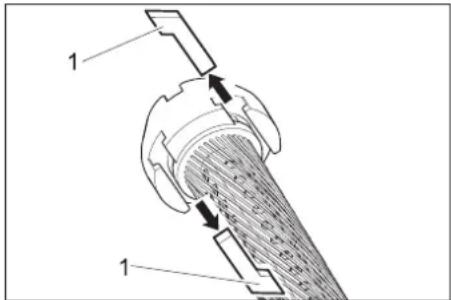
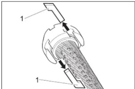
Technical diagram of a mechanical device with labeled components and directional arrows indicating flow or movement.1 Grooved stone
→ Pullout the grooved stones between the upper part and the filter inlay and between the lower part and the filter inlay.
→ Remove upper and lower part of filter inlay.
→ Remove filtrate pipe from filtrate inlay,
→ Dispose of the filter inlay.
→ Attach filtrate pipe at one end of the new filter inlay.
→ Tighten the filter inlay in such a way that the filaments do not twist.
→ Push the filtrate pipe in the filter inlay and by looking at the opposite side of the filter element push the inlay in the direction of the filtrate pipe.
→ Coat all rings with normal liquid soap before carrying out any further installation tasks.
NOTICE
Do not use silicon grease. Silicon in water will hamper the cleaning and drying effect during vehicle wash.
→ Insert the upper and lower part on the filter element.
→ Align the upper and lower part in such a way that the grooved stones can be inserted.
natural_image
Cross-sectional diagram of a mechanical component with internal structure and directional arrows (no text or labels)→ Insert the grooved stones and clamp it tight by slightly turning the filter inlay.
→ Insert the lower part into the filament filter and push it in completely.
→ Replace the filament filter lid.
→ Place the filament filter on the lower console so that both the rear pins lock into the long-holes of the console.

text_image
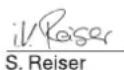
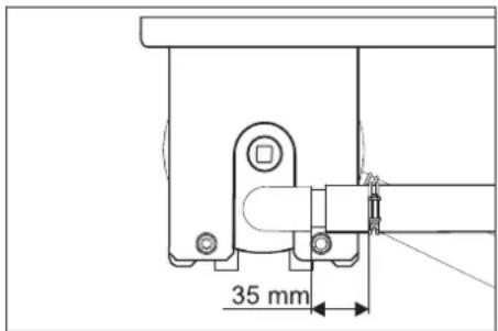
35 mm→ Align the lid, as shown above, and push it in completely.
→ Push in the filament filter between the two consoles.
→ Hook in the threaded rod assembly at the lower console and insert the threaded rods through the holes in the upper console.
→ Fasten the threaded rods with undelay washers and nuts.
→ Tighten the nuts in such a way that the underlay washers can be still be moved by hand.
→ Insert the hoses onto the hose fittings.
→ Tighten the hose clamps (keep the 35 mm distance).
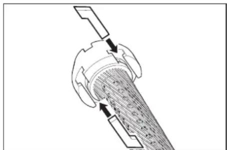
→ Insert the tension lever with bearing through the lid of the filament filter.
natural_image
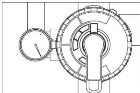
Technical line drawing of a mechanical assembly with no visible text or symbols→ Turn the tightening lever in clockwise direction. It should be possible to turn
the tightening lever in the range shown above without exerting any pressure. Otherwise, dismantle the tightening lever and insert it again in the correct position.
→ Fasten the tension lever bearings with screws.
→ Adjust the filter pre-tension.
Troubleshooting
DANGER
Risk of accident while working on the unit. During all tasks
→ Switch off the immersion pump in the building.
Who may remedy faults?
- Operator
Work designated with the sign "Operator" may only be carried out by persons who have been instructed in the safe operation and maintenance on the wash plant
- Customer Service
Work designated with the sign "Customer Service" may only be done by the fitters of Kärcher Customer Service or fitters who have been authorised by Kärcher.
| Fault Possible cause | Remedy By whom | ||
| Plant out of order Power supply to the pump in the building is interrupted. | Check power supply and ensure proper supply. Operator | ||
| Processed water is coloured or is foaming too much | Filter pre-tension is not correct. Adjust the filter pre-tension Operator | ||
| Filter inlay is defective (leaky) Replacing filter inlay Operator, Cus- | tomer Service | ||
| Sludge collector or pump basin is dirty Emptying and cleaning the basins Operator/ Disposal agency | |||
| Improper detergents are used in the washing hall | Use compatible detergents; rinse the system, if necessary | Operator, Customer Service | |
| Cleaning dose is too high | Check detergent dosing; reset, if necessary | Operator, Customer Service | |
| Washing place cleaned with incompatible detergents | Replace water and rinse the basins | Operator | |
| Filter output is too low | Filament filter is blocked | Backwash the filament filter; clean or replace filter inlay if required. | Operator |
| Immersion pump is of lesser dimension | Install a suitable immersion pump (see requirements under "Technical Data") | Operator | |
| Immersion pump is blocked, defective | Clean, repair, replace immersion pump | Operator, Customer Service | |
| Pipe or valve is leaky, defective, blocked | Check pipes and valves; clean, repair or replace as required | Operator, Customer Service | |
| Filter is not clean following the back-wash | Filter inlay is very dirty. | Removing the filter inlay (see "Replacing the filter inlay").Dissolve 1 Tab of RM 760 in 5 litres of warm water.Soak the filter inlay for 30 minutes and wash by hand and squeeze afterwards.Rinse the filter inlay with clear water.If required, repeat the washing procedure.Dispose of detergent.Install a new filter inlay. | Operator |
Accessories
Filter inlay
Order No. 5.033-239.0
Filter fill active carbon filter
Order No. 4.414-014.0
Funnel
Order No. 4.901-090.0
Special funnel to fill in the active carbon filter filling
Attachment kit active carbon filter
Order No. 2.641-831.0
Additional active carbon filter
Attachment set 'Fresh water switching'
Order No. 2.641-521.0
Manual switching between processed/fresh water for using fresh water in the high-pressure cleaner (for e.g. for rinsing).
Attachment set input valve
Order No. 4.640-230.0
To throttle a raw water pump that is running too high.
Attachment kit ventilation
Order No. 2.641-510.0
Usage water ventilation to avoid bothersome odours
Attachment kit overflow
Order No. 2.641-868.0
Second floater switch in the pump basin, emits signal to external alarm setup, if the pump basin is too full
Attachment kit support leg
Order No. 2.641-849.0
Support legs for filter module, if a wall mounting is not possible
Immersion pump
Order No. 6.474-073.0
Immersion pump as raw water pump
EU Declaration of Conformity
We hereby declare that the machine described below complies with the relevant basic safety and health requirements of the EU Directives, both in its basic design and construction as well as in the version put into circulation by us. This declaration shall cease to be valid if the machine is modified without our prior approval.
Product: Effluent treatment plant
Type: 1.217-xxx
Relevant EU Directives
2006/95/EEC
2014/30/EU
Applied harmonized standards
EN 60204-1
EN 55014-1: 2006+A1: 2009+A2: 2011
EN 55014-2: 2015
EN 61000-3-2: 2014
EN 61000-3-3: 2013
EN 62233: 2008
The signatories act on behalf of and with the authority of the company management.

Chairman of the Board of Management

Director Regulatory Affairs & Certification
Documentation supervisor:
S. Reiser
Alfred Kärcher SE & Co. KG
71364 Winnenden (Germany)
Tel.: +49 7195 14-0
Fax: +49 7195 14-2212
Winnenden, 2018/10/01
Installing the unit (only for experts)
Notice
The equipment may only be installed by an – mechanic of Kärcher
- or an from Kärcher authorized individual
Preparing the installation place
The following requirements are necessary in order to install the equipment:
- frost-free room with adequate ventilation and exhausts
– sufficient lighting at the installation site
– Floor path for collecting sludge
– Strong wall for fastening the system - The ground must be stable and tight.
Unpack the equipment
Unpack the equipment and dispose of the packing material properly.
Electrical installation
The machine must have an FI fuse of type B, 30 mA.
The electrical connection of the system may only be performed by a qualified electrician. Please follow the respective national regulations!
Electrical installation as per IEC 60364-1
Water installation
The water installation depends on the specific conditions of the existing plant components such as
- Type and model of high pressure cleaner
NOTICE
The processed water outlet of the system is directly connected to the water inlet of the high-pressure cleaner. This can lead to foam formation in the swimmer tank in high-pressure cleaners with a swimmer tank. In such a case, the high-pressure cleaner must be switched to suction operations (see separate operating instructions of the high-pressure cleaner).
- Type and models of building-side components (sludge collector, pump basin, etc.)
– Nominal widtht, lengths and type of channels
Hence, the water installation must be done according to the specific local conditions. The immersion pump specifications in the building must meet the requirements outline in the "Technical Data / Immersion Pump Requirements" section.
DANGER
Risk of injury on account of tripping and falling.
Lay the hoses of the plant in such a way that they do not pose a risk for tripping and falling.
NOTICE
During startup, set the multi-channel valve to the position "BACKWASH" and rinse the system until all bubbles have escaped from the filament filter. After that, set the multi-channel valve to "FILTRATION".
www.kaercher.com/REACH
Garantie
– disposer des qualifications requises,
text_image
Technical diagram of a mechanical device with numbered components and labeled parts, including zoomed-in views for detail.1 Levier de serrage
natural_image
Technical line drawing of a mechanical component with no visible text or symbolstext_image
Technical schematic diagram of a gas or fluid system with numbered components and directional flow indicatorsnatural_image
Close-up of a transparent plastic container with a curved lid, placed on a grid surface (no text or symbols visible)natural_image
Close-up of a transparent cylindrical container with a circular top, placed on a textured surface (no text or symbols visible)text_image
Technical diagram of a mechanical device with numbered components and cross-sectional viewstext_image
Technical diagram of a mechanical component with labeled parts and directional arrows indicating motion or flow.1 Coulisseau
natural_image
Cross-sectional diagram of a mechanical component with internal structure and directional arrows (no text or labels)natural_image
Technical line drawing of a mechanical assembly with no visible text or symbols
Chairman of the Board of Management

S. Reiser
Director Regulatory Affairs & Certification
Responsable de la documentation : S. Reiser
Alfred Kärcher SE & Co. KG
71364 Winnenden (Germany)
Tel.: +49 7195 14-0
Fax: +49 7195 14-2212
Winnenden, 2018/10/01
www.kaercher.com/REACH
Garanzia
text_image
Technical diagram of a mechanical device with numbered components and labeled parts, including zoomed-in views for detail.natural_image
Technical line drawing of a mechanical component with gauges and housing (no text or symbols)text_image
Technical schematic diagram of a gas or fluid system with numbered components and directional flow indicatorsnatural_image
Close-up of a transparent plastic container with internal layers, placed on a grid surface (no text or symbols visible)natural_image
Close-up of a transparent cylindrical container with a circular top, placed on a grid surface (no visible text or symbols)text_image
Technical diagram of a mechanical device with numbered components and labeled parts1 Dado
text_image
Technical diagram of a mechanical device with labeled components and directional arrows indicating motion or flow.1 Dado scanalato
natural_image
Diagram of a mechanical device with internal components and directional arrows (no text or symbols)natural_image
Technical line drawing of a mechanical assembly with no visible text or symbols
Chairman of the Board of Management
Director Regulatory Affairs & Certification
71364 Winnenden (Germany)
Tel.: +49 7195 14-0
Fax: +49 7195 14-2212
Winnenden, 2018/10/01
www.kaercher.com/REACH
Garantie
text_image
Technical diagram of a mechanical device with numbered components and labeled parts, including zoomed-in views for detail.1 Spanhefboom
2 Ontgrendelhefboom
3 Draadfilter
4 Meerwegventiel
5 Manometer Filteringang
6 Overstroomklep
7 Smoorklep **)
natural_image
Technical line drawing of a mechanical component with no visible text or symbols→ Hefboom van de meerwegklep in stand „FILTREREN“ draaien.
OPMERKING
text_image
Technical schematic diagram of a gas or fluid system with numbered components and flow pathsnatural_image
Close-up of a transparent plastic container with liquid, placed on a grid surface (no text or symbols visible)natural_image
Close-up of a glass beaker containing a white liquid with a circular top (no text or symbols visible)text_image
Technical diagram of a mechanical device with numbered components and cross-sectional views1 Moer
text_image
Technical diagram of a mechanical device with labeled components and directional arrows indicating flow or movement.1 T-moer
natural_image
Diagram of a mechanical component with internal structure and directional arrows (no text or symbols)natural_image
Technical line drawing of a mechanical assembly with no visible text or symbols
Chairman of the Board of Management

Director Regulatory Affairs & Certification
71364 Winnenden (Germany)
Tel.: +49 7195 14-0
Fax: +49 7195 14-2212
Winnenden, 2018/10/01
www.kaercher.com/REACH
Garantía
text_image
Technical diagram of a mechanical device with numbered components and labeled parts, including zoomed-in views and assembly details.natural_image
Technical line drawing of a mechanical component with no visible text or symbolstext_image
Technical schematic diagram of a gas or fluid system with numbered components and flow pathsnatural_image
Close-up of a transparent cylindrical container with liquid, placed on a grid surface (no text or symbols visible)natural_image
Close-up of a transparent cylindrical container with a circular top, placed on a grid surface (no text or symbols visible)text_image
Technical diagram of a mechanical device with numbered components and exploded viewstext_image
Technical diagram of a mechanical device with labeled components and directional arrows indicating flow or movement.1 Tuerca deslizante
natural_image
Cross-sectional diagram of a mechanical component with internal structure and directional arrows (no text or labels)natural_image
Technical line drawing of a mechanical assembly with no visible text or symbols
Chairman of the Board of Management

S. Reiser
Director Regulatory Affairs & Certification
71364 Winnenden (Germany)
Tel.: +49 7195 14-0
Fax: +49 7195 14-2212
Winnenden, 2018/10/01
text_image
Technical diagram of a mechanical device with numbered components and labeled parts, including zoomed-in views for detail.natural_image
Technical line drawing of a mechanical component with no visible text or symbolstext_image
Technical schematic diagram of a gas or fluid system with numbered components and flow pathsnatural_image
Close-up of a transparent plastic container with internal layers, placed on a grid surface (no text or symbols visible)natural_image
Close-up of a glass beaker containing a white liquid with bubbles, placed on a tiled surface (no text or symbols visible)text_image
Technical diagram of a mechanical device with numbered components and exploded views1 Porca
2 Alavanca de tensionamento
text_image
Technical diagram of a mechanical device with labeled components and directional arrows indicating motion or flow.1 Lingueta
natural_image
Cross-sectional diagram of a mechanical component with internal structure and directional arrows (no text or labels)natural_image
Technical line drawing of a mechanical assembly with no visible text or symbols
Chairman of the Board of Management

S. Reiser
Director Regulatory Affairs & Certification
71364 Winnenden (Germany)
Tel.: +49 7195 14-0
Fax: +49 7195 14-2212
Winnenden, 2018/10/01
www.kaercher.com/REACH
Garanti
text_image
Technical diagram of a mechanical device with numbered components and labeled parts, including zoomed-in views for detail.natural_image
Technical line drawing of a mechanical component with no visible text or symbolstext_image
Technical schematic diagram of a gas or fluid system with numbered components and flow pathsnatural_image
Close-up of a transparent plastic container with liquid, placed on a grid surface (no text or symbols visible)natural_image
Close-up of a glass beaker containing a white liquid, no visible text or symbolstext_image
Technical diagram of a mechanical device with numbered components and cross-sectional viewstext_image
Technical diagram of a mechanical device with labeled components and directional arrows indicating flow or movement.1 Notsten
natural_image
Cross-sectional diagram of a mechanical component with internal structure and directional arrows (no text or labels)natural_image
Technical line drawing of a mechanical assembly with no visible text or symbolsIndustrivandsventilation for at undgå lugt-gene

Chairman of the Board of Management
Director Regulatory Affairs & Certification
71364 Winnenden (Germany)
Tel.: +49 7195 14-0
Fax: +49 7195 14-2212
Winnenden, 2018/10/01
www.kaercher.com/REACH
Garanti
text_image
Technical diagram of a mechanical device with numbered components and labeled parts, including zoomed-in views for detail.1 Spennhendel
2 Låsespake
3 Filamentfilter
4 Flerveisventil
5 Manometer filteringngang
6 Overstrømsventil
7 Strupeventil**)
8 Manometer aktivt kull-filter
9 Aktivkullfilter
Stille inn filterforspenning
natural_image
Technical line drawing of a mechanical component with no visible text or symbols→ Kontroller filterforspenning.
→ Sett pumpen på byggsiden i drift.
Returskylling
MERKNAD
text_image
Technical schematic diagram of a gas or fluid system with numbered components and flow pathsVed spyling strømmer vannet over:
- Sugepumpe
- Multiventil i stilling "FORFILTRERING/RINSE"
- Filter (flytretning filtere)
- i slamfangeren
SIRKULASJON/RECIRCULATION
natural_image
Close-up of a transparent plastic container with a curved lid, placed on a grid surface (no text or symbols visible)natural_image
Close-up of a glass beaker containing a white liquid with a circular top (no text or symbols visible)text_image
Technical diagram of a mechanical device with numbered components and cross-sectional views1 Mutter
2 Spennhendel
3 Skrue spennhendellager
4 Slangeklemme
5 Deksel
6 Overdel
7 Filterinnsats
8 Filtratrør
9 Gjengebolt
10 Filamentfilter
11 Underdel
12 Nedre konsoll
13 Stift
text_image
Technical diagram of a mechanical assembly with labeled components and directional arrows indicating motion or force.1 Festeblokk
natural_image
Cross-sectional diagram of a mechanical component with internal structure and directional arrows (no text or labels)natural_image
Technical line drawing of a mechanical assembly with no visible text or symbols→ Vri spennhendel med klokka. Spennhendelen skal kunne dreies i området

Chairman of the Board of Management

Director Regulatory Affairs & Certification
71364 Winnenden (Germany)
Tel.: +49 7195 14-0
Fax: +49 7195 14-2212
Winnenden, 2018/10/01
www.kaercher.com/REACH
Garanti
text_image
Technical diagram of a mechanical device with numbered components and labeled parts, including zoomed-in views for detail.1 Spännarm
2 Spärrspak
3 Filamentfilter
4 Flervägsventil
natural_image
Technical line drawing of a mechanical component with no visible text or symbolstext_image
Technical schematic diagram of a gas or fluid system with numbered components and flow pathsnatural_image
Close-up of a transparent plastic container with liquid, placed on a grid surface (no text or symbols visible)natural_image
Close-up of a transparent cylindrical container with a circular top, placed on a grid surface (no text or symbols visible)text_image
Technical diagram of a mechanical device with numbered components and cross-sectional views1 Mutter
2 Spännarm
text_image
Technical diagram of a mechanical device with labeled components and directional arrows indicating flow or movement.1 Notkloss
natural_image
Cross-sectional diagram of a mechanical component with internal structure and directional arrows (no text or labels)natural_image
Technical line drawing of a mechanical assembly with no visible text or symbols
Chairman of the Board of Management
Director Regulatory Affairs & Certification
71364 Winnenden (Germany)
Tel.: +49 7195 14-0
Fax: +49 7195 14-2212
Winnenden, 2018/10/01
www.kaercher.com/REACH
Takuu
text_image
Technical diagram of a mechanical device with numbered components and labeled parts, including zoomed-in views for detail.1 Kiristyskahva
2 Vapautusvipu
natural_image
Technical line drawing of a mechanical component with no visible text or symbolstext_image
Technical schematic diagram of a gas or fluid system with numbered components and flow pathsnatural_image
Close-up of a transparent plastic container with layered liquid, placed on a grid surface (no text or symbols visible)natural_image
Close-up of a transparent cylindrical container with a white circular top, placed on a textured surface (no text or symbols visible)text_image
Technical diagram of a mechanical device with numbered components and cross-sectional viewstext_image
Technical diagram of a mechanical component with labeled parts and directional arrows indicating motion or flow.1 T-urakiinnitin
natural_image
Technical diagram of a mechanical component with internal structure and directional arrows (no text or labels)natural_image
Technical line drawing of a mechanical assembly with no visible text or symbols
Chairman of the Board of Management

S. Reiser
Director Regulatory Affairs & Certification
71364 Winnenden (Germany)
Tel.: +49 7195 14-0
Fax: +49 7195 14-2212
Winnenden, 2018/10/01
text_image
Technical diagram of a mechanical device with numbered components and labeled parts, including zoomed-in views for detail.natural_image
Technical line drawing of a mechanical component with gauges and housing (no text or symbols)natural_image
Close-up of a transparent plastic container with liquid, placed on a grid surface (no text or symbols visible)natural_image
Close-up of a transparent cylindrical container with a circular top, placed on a grid surface (no visible text or symbols)text_image
Technical diagram of a mechanical device with numbered components and cross-sectional views1 Περικόχλιο
2 Μοχλός σύσφιξης
text_image
Technical diagram of a mechanical component with labeled parts and directional arrows indicating flow or movement.1 Γλωσσίδα
natural_image
Diagram of a mechanical component with internal structure and directional arrows (no text or symbols)natural_image
Technical line drawing of a mechanical assembly with no visible text or symbols
Chairman of the Board of Management
Director Regulatory Affairs & Certification
71364 Winnenden (Germany)
Tel.: +49 7195 14-0
Fax: +49 7195 14-2212
Winnenden, 2018/10/01
www.kaercher.com/REACH
Garanti
text_image
Technical diagram of a gas pump system with numbered components and labeled partsnatural_image
Technical line drawing of a mechanical component with a pressure gauge and central shaft (no text or symbols)text_image
Technical schematic diagram of a gas or fluid system with numbered components and flow pathsnatural_image
Close-up of a transparent plastic container with liquid, placed on a grid surface (no text or symbols visible)natural_image
Close-up of a transparent cylindrical container with a white liquid, placed on a textured surface (no visible text or symbols)text_image
Technical diagram of a mechanical device with numbered components and cross-sectional views1 Somun
2 Gergi kolu
text_image
Technical diagram of a mechanical device with labeled components and directional arrows indicating flow or movement.1 Oluk taşı
natural_image
Diagram of a mechanical component with internal structure and directional arrows (no text or symbols)natural_image
Technical line drawing of a mechanical assembly with no visible text or symbols
Chairman of the Board of Management

Director Regulatory Affairs & Certification
71364 Winnenden (Germany)
Tel.: +49 7195 14-0
Fax: +49 7195 14-2212
Winnenden, 2018/10/01
www.kaercher.com/REACH
Гарантия
text_image
Technical diagram of a mechanical device with numbered components and labeled parts, including zoomed-in views for detail.natural_image
Technical line drawing of a mechanical component with a pressure gauge and central shaft (no text or symbols)natural_image
Close-up of a transparent plastic container with a coiled lid, placed on a grid surface (no text or symbols visible)natural_image
Close-up of a transparent cylindrical container with a circular top, placed on a grid surface (no visible text or symbols)text_image
Technical diagram of a mechanical device with numbered components and cross-sectional viewstext_image
Technical diagram of a mechanical device with labeled components and directional arrows indicating flow or movement.natural_image
Cross-sectional diagram of a mechanical component with internal structure and directional arrows (no text or labels)natural_image
Technical line drawing of a mechanical assembly with no visible text or symbols
11. Jennifer
Chairman of the Board of Management
S. Reiser
Director Regulatory Affairs & Certification
71364 Winnenden (Germany)
Tel.: +49 7195 14-0
Fax: +49 7195 14-2212
Winnenden, 2018/10/01
www.kaercher.com/REACH
Garancia
text_image
Technical diagram of a mechanical device with numbered components and labeled parts, including zoomed-in views for detail.1 Feszítőkar
2 Kioldókar
3 Finomszálas szűrő
4 Többutas szelep
natural_image
Technical line drawing of a mechanical component with no visible text or symbolstext_image
Technical schematic diagram of a gas or fluid system with numbered components and flow pathsnatural_image
Close-up of a transparent plastic cup filled with white liquid, placed on a grid surface (no text or symbols visible)natural_image
Close-up of a transparent cylindrical container with a circular top, placed on a grid surface (no text or symbols visible)text_image
Technical diagram of a mechanical device with numbered components and exploded views, likely for assembly or maintenance instructions.1 Anya
2 Feszítökar
text_image
Technical diagram of a mechanical device with labeled components and directional arrows indicating flow or movement.1 Csúszótömb
natural_image
Cross-sectional diagram of a mechanical component with internal structure and directional arrows (no text or labels)natural_image
Technical line drawing of a mechanical assembly with no visible text or symbols
Chairman of the Board of Management

S. Reiser
Director Regulatory Affairs & Certification
71364 Winnenden (Germany)
Tel.: +49 7195 14-0
Fax: +49 7195 14-2212
Winnenden, 2018/10/01
www.kaercher.com/REACH
Záruka
text_image
Technical diagram of a mechanical device with numbered components and labeled parts, including zoomed-in views for detail.1 Upínací páčka
2 Uvolňovací páka
3 Vlákenový filtr
4 Vícecestný ventil
natural_image
Technical line drawing of a mechanical component with no visible text or symbolstext_image
Technical schematic diagram of a gas or fluid system with numbered components and flow pathsnatural_image
Close-up of a transparent plastic container with a coiled lid, placed on a grid surface (no text or symbols visible)natural_image
Close-up of a transparent cylindrical container with a circular top, placed on a tiled surface (no visible text or symbols)text_image
Technical diagram of a mechanical device with numbered components and exploded views, likely for assembly or maintenance instructions.1 Matice
text_image
Technical diagram of a mechanical device with labeled components and directional arrows indicating flow or movement.1 Vodicí vložka
natural_image
Diagram of a mechanical device with internal components and directional arrows (no text or symbols)natural_image
Technical line drawing of a mechanical assembly with no visible text or symbols
Chairman of the Board of Management
Director Regulatory Affairs & Certification
71364 Winnenden (Germany)
Tel.: +49 7195 14-0
Fax: +49 7195 14-2212
Winnenden, 2018/10/01
www.kaercher.com/REACH
Garancija
text_image
Technical diagram of a mechanical device with numbered components and labeled parts, including zoomed-in views for detail.natural_image
Technical line drawing of a mechanical component with no visible text or symbolstext_image
Technical schematic diagram of a gas or fluid system with numbered components and flow pathsnatural_image
Close-up of a transparent plastic container with a curved lid, placed on a grid surface (no text or symbols visible)Slika penjenja filtra v redu: zelo tanek prstan pene na robu, ki hitro razpade.
natural_image
Close-up of a transparent cylindrical container with a circular top, resting on a textured surface (no visible text or symbols)Slika penjenja izčrpanega filtra: debel prstan pene na robu, ki ne razpade.
Menjava aktivnega olja
text_image
Technical diagram of a mechanical device with numbered components and cross-sectional views1 Matica
2 Napenjalo
3 Vijak ležaja napenjala
4 Objemka za gibko cev
5 Pokrov
6 Zgornji del
7 Filtrni vložek
8 Cev za filtrat
9 Drog z navojem
10 Filamentni filter
11 Spodnji del
12 Spodnja konzola
13 Zatič
→ Sprostite filter.
→ Odprite objemke za gibko cev.
→ Gibke cevi snemite z nastavkov za gibke cevi.
→ Izvijte oba vijaka ležaja napenjala.
text_image
Technical diagram of a mechanical device with labeled components and directional arrows indicating motion or flow.1 Matica vijaka z režo
natural_image
Cross-sectional diagram of a mechanical component with internal structure and directional arrows (no text or labels)→ Vtaknite matice vijaka z režo in prižemite z rahlim obračanjem filtrnega vložka.
→ Spodnji del vstavite v filamentni filter in povsem potisnite notri.
→ Pokrov namestite na filamentni filter.
→ Filamentni filter postavite na spodnjo konzolo, da oba zadnja zatiča sedita v vodoravnih luknjah konzole.

text_image
35 mm→ Kot prikazano zgoraj, pokrov naravnajte in popolnoma potisnite notri.
→ Filamentni filter potisnite med obe konzoli.
→ Sklop drogov z navojem pritrdite s kavljem na spodnjo konzolo in drogove z navojem vtaknite skozi izvrtine v zgornji konzoli.
→ Drogove z navojem pritrdite s podložkami in maticami.
natural_image
Technical line drawing of a mechanical assembly with no visible text or symbols→ Napenjalo zavrtite v smeri urnega kazalca. Napenjalo mora biti mogoče brez

Chairman of the Board of Management

Director Regulatory Affairs & Certification
71364 Winnenden (Germany)
Tel.: +49 7195 14-0
Fax: +49 7195 14-2212
Winnenden, 2018/10/01
www.kaercher.com/REACH
Gwarancja
text_image
Technical diagram of a gas pump system with numbered components and labeled parts1 Dźwignia mocująca
natural_image
Technical line drawing of a mechanical component with a pressure gauge and central shaft (no text or symbols)text_image
Technical schematic diagram of a gas or fluid system with numbered components and directional flow indicatorsnatural_image
Close-up of a transparent plastic container with liquid, placed on a grid surface (no text or symbols visible)natural_image
Close-up of a glass beaker containing a white liquid with a circular top (no text or symbols visible)text_image
Technical diagram of a mechanical device with numbered components and cross-sectional viewstext_image
Technical diagram of a mechanical device with labeled components and directional arrows indicating flow or movement.1 Kamień ustalający
natural_image
Cross-sectional diagram of a mechanical component with internal structure and directional arrows (no text or labels)natural_image
Technical line drawing of a mechanical assembly with no visible text or symbols
Chairman of the Board of Management

Director Regulatory Affairs & Certification
71364 Winnenden (Germany)
Tel.: +49 7195 14-0
Fax: +49 7195 14-2212
Winnenden, 2018/10/01
www.kaercher.com/REACH
Garantie
text_image
Technical diagram of a mechanical device with numbered components and labeled parts, including zoomed-in views for detail.natural_image
Technical line drawing of a mechanical component with a pressure gauge and central shaft (no text or symbols)text_image
Technical schematic diagram of a fluid system with numbered components and piping connectionsnatural_image
Close-up of a transparent plastic container with liquid, placed on a grid surface (no text or symbols visible)natural_image
Close-up of a transparent cylindrical container with a circular top, placed on a grid surface (no visible text or symbols)text_image
Technical diagram of a mechanical device with numbered components and exploded viewstext_image
Technical diagram of a mechanical device with labeled components and directional arrows indicating motion or flow.1 Culisor
natural_image
Cross-sectional diagram of a mechanical component with internal structure and directional arrows (no text or labels)natural_image
Technical line drawing of a mechanical assembly with no visible text or symbolsDirective UE respectate:
2006/95/CE
2014/30/UE
Norme armonizate utilize:
EN 60204-1
EN 55014-1: 2006+A1: 2009+A2: 2011
EN 55014-2: 2015
EN 61000-3-2: 2014
EN 61000-3-3: 2013
EN 62233: 2008

Chairman of the Board of Management
Director Regulatory Affairs & Certification
71364 Winnenden (Germany)
Tel.: +49 7195 14-0
Fax: +49 7195 14-2212
Winnenden, 2018/10/01
www.kaercher.com/REACH
Záruka
text_image
Technical diagram of a gas pump system with numbered components and labeled parts1 Upínacia páka
2 Uvolňovacia páka
3 Filter z vlákien
4 Viaccestný ventil
5 Tlakomer na vstupe filtra
6 Prepúšťací ventil
7 Škrtiaci ventil **)
natural_image
Technical line drawing of a mechanical component with no visible text or symbols→ Páku viaccestného ventilu otočte do polohy „FILTRATION/FILTRÁCIA“.
POKYN
text_image
Technical schematic diagram of a gas or fluid system with numbered components and directional flow indicatorsnatural_image
Close-up of a transparent plastic container with liquid, placed on a grid surface (no text or symbols visible)natural_image
Close-up of a transparent cylindrical container with a circular white liquid inside, placed on a grid surface (no text or symbols visible)text_image
Technical diagram of a mechanical device with numbered components and cross-sectional viewstext_image
Technical diagram of a mechanical device with labeled components and directional arrows indicating flow or movement.1 Vodiaca vložka
natural_image
Cross-sectional diagram of a mechanical component with internal structure and directional arrows (no text or labels)→ Nasad'te vodiace vložky a upevnite miernym otočením vložky filtra.
→ Spodnú čast' nasad'te do filtra s vlákna-mi a celkom zasuňte.
→ Na filter s vláknami nasad'te veko.
→ Filter s vláknami nasad'te na spodnú konzolu tak, aby obidva zadné kolíky zapadli do pozdlžnych otvorov konzoly.
text_image
35 mmnatural_image
Technical line drawing of a mechanical assembly with no visible text or symbols
Chairman of the Board of Management
Director Regulatory Affairs & Certification
71364 Winnenden (Germany)
Tel.: +49 7195 14-0
Fax: +49 7195 14-2212
Winnenden, 2018/10/01
www.kaercher.com/REACH
Jamstvo
text_image
Technical diagram of a mechanical device with numbered components and labeled parts, including zoomed-in views for detail.natural_image
Technical line drawing of a mechanical component with no visible text or symbolstext_image
Technical schematic diagram of a gas or fluid system with numbered components and flow paths1 ka spremniku potrošne vode / visokotlačnom čistaču
2 kanalizacije *)
3 Kontrolno okno *)
4 Uronjiva pumpa *)
5 Bazen crpke sustava za recikliranje *)
6 Separator (EN 858) *)
7 Sakupljanje mulja sustava za recikliranje *)
8 Cirkulacija (ka odmuljivaču)
9 Vod za povratno ispiranje
10 Prigušni ventil
11 Sigurnosni ventil
12 Manometar, ulaz filtra
13 Višesmjerni ventil
14 Vlaknasti filtar
15 Manometar, filtar s aktivnim ugljenom
16 Filtar s aktivnim ugljenom
17 Ventil za uzimanje uzoraka **)
18 2. Filtar s aktivnim ugljenom **)
19 Magnetski ventil
20 Prigušnica
21 Crijevo za filtrat
22 Preljevni ventil
*) od strane investitora
**) Opcija
Opis funkcije
natural_image
Close-up of a transparent plastic container with visible internal bands, placed on a grid surface (no text or symbols)Izgled pjene kada je filtar u redu: vrlo tanak prsten od pjene po obodu koji se brzo raspada.
natural_image
Close-up of a transparent cylindrical container with a circular top, placed on a textured surface (no visible text or symbols)Izgled pjene kada je filtar istrošen: debeo prsten od pjene po obodu koji se ne raspada.
text_image
Technical diagram of a mechanical device with numbered components and cross-sectional views1 Matica
2 Stezna poluga
3 Vijak ležaja stezne poluge
4 Obujmica za crijevo
5 Poklopac
6 Gornji dio
7 Filtarski umetak
8 Cijev za filtrat
9 Navojna šipka
10 Vlaknasti filtar
11 Donji dio
12 Donja konzola
13 Zatik
→ Otpustite filtar.
→ Otvorite obujmice za crijevo.
→ Skinite crijeva s crijevnih priključaka.
→ Odvijte oba vijka ležaja stezne poluge.
→ Steznu polugu zajedno s ležištem skinite prema gore.
→ Odvijte matice na gornjem kraju navojne šipke.
→ Skinite sklop navojnih šipki.
→ Izvucite vlaknasti filtar prema naprijed.
→ Skinite poklopac vlaknastog filtra.
→ Skinte donji dio vlaknastog filtra zajedno s filtarskim uloškom.
text_image
Technical diagram of a mechanical component with labeled parts and directional arrows indicating motion or flow.1 Element s utorima
natural_image
Cross-sectional diagram of a mechanical component with internal structure and directional arrows (no text or labels)→ Umetnite elemente s utorima i laganim okretanjem učvrstite filtarski uložak.
→ Donji dio postavite u vlaknasti filtar i potpuno ugurajte.
→ Postavite poklopac na vlaknati filtar.
→ Vlaknasti filtar postavite na donju konzolu tako da oba stražnja zatika sjednu u uzdužne rupe konzole.
text_image
35 mm→ Poklopac centrirajte kako je prikazano gore i potpuno ugurajte.
→ Vlaknasti filtar gurnite između obje konzole.
→ Sklop s navojnim šipkama zakačite na donju konzolu i umetnite navojne šipke kroz provrte u gornjoj konzoli.
→ Navojne šipke učvrstite podloškama i maticama.
→ Matice pritegnite samo toliko da se podloške još mogu pomicati rukom.
→ Priključite crijeva na priključke za crijeva.
→ Pritegnite obujmice za crijeva (održavajte razmak od 35 mm).
→ Kroz poklopac vlaknastog filtra postavite steznu polugu s ležištem.

natural_image
Technical line drawing of a mechanical assembly with no visible text or symbols→ Steznu polugu okrenite u smjeru kazaljke na satu. Stezna poluga mora se moći okretati bez primjene sile u gore prikazanom području. U suprotnom, demontirajte steznu polugu i još jednom je postavite u ispravljeni položaj.
→ Pomoću oba vijka učvrstite ležaj stezne poluge.
→ Podesite prednapetost filtra.
Pomoć u slučaju smetnji
⚠ OPASNOST
Opasnost od ozljeda pri radovima na stroju. Kod svih radova

Chairman of the Board of Management

Director Regulatory Affairs & Certification
Opunomoćeni za izradu dokumentacije: S. Reiser
Alfred Kärcher SE & Co. KG
71364 Winnenden (Germany)
Tel.: +49 7195 14-0
Fax: +49 7195 14-2212
Winnenden, 2018/10/01
Instaliranje stroja (samo za stručno osoblje)
Napomena
www.kaercher.com/REACH
Garancija
U svakoj zemlji važe garantni uslovi koje je izdala naša nadležna distributivna organizacija. Eventualne smetnje na uređaju za vreme trajanja garancije otklanjamo besplatno, ukoliko je uzrok greška u materijalu ili proizvodnji. U slučaju koji podleže garanciji obratite se sa potvrdom o kupovini Vašem prodavcu ili najbližoj ovlašćenoj servisnoj službi.
Simboli u uputstvu za rad
△OPASNOST
Ukazuje na neposredno preteću opasnost koja dovodi do teških telesnih povreda ili smrti.
⚠UPOZORENJE
Ukazuje na eventualno opasnu situaciju koja može dovesti do teških telesnih povreda ili smrti.
OPREZ
Ukazuje na eventualno opasnu situaciju koja može dovesti do lakših telesnih povreda ili izazvati materijalnu štetu.
Namensko korišćenje
Uređaj čisti otpadnu vodu koja se dobija nakon pranja motornih vozila i na raspolaganje stavlja potrošnu vodu za visokopritisne uređaje za čišćenje (maksimalno 1200 l/h). Potrošna voda se može koristiti samo za programe pranja (npr. predpranje, visokopritisno pranje). Potrošna voda nije prikladna za ispiranje kao ni za nanošenje sredstava za ubrzavanje sušenja ili u druge svrhe.
Čišćenje sledi kroz:
– Separacija čestica koje se teško talože u filteru sa filamentom.
Ako nivo vode u koritu pumpe premašuje određenu visinu, otvara se magnetni ventil i voda se preko filtera sa aktivnim ugljem sprovodi u kanalizaciju.
Preduslovi za besprekorno funkcionisanje:
– Sistem korita u skladu sa šemom vode u poglavlju "Funkcija".
– Maksimalni dovod vode 2000 l/h.
- Minimalni dovod vode 1200 l/h.
text_image
Technical diagram of a mechanical device with numbered components and labeled parts, including zoomed-in views for detail.1 Do rezervoara reciklirane vode
2 Otkočna poluga
3 Filamentni filter
4 Ventil više puteva
5 Manometar, ulaz filtera
6 Prelivni ventil
7 Prigušni ventil **)
8 Manometar, filter sa aktivnim ugljem
9 Filter sa aktivnim ugljem
10 Crevna spojnica, izlaz filtera sa aktivnim ugljem
11 Crevna spojnica, ulaz filtera sa aktivnim ugljem
12 Sigurnosni ventil
13 Blenda
14 Crevo za filtrat
15 Prekidač magnetnog ventila
16 2. Filter sa aktivnim ugljem **)
17 Ventil za uzimanje uzoraka **)
18 Magnetni ventil
A Ka odmuljivaču
B ka odmuljivaču (povratno ispiranje)
C od potopne pumpe
D Ka odmuljivaču (nadpritisak)
E ka visokopritisnom uređaju za čišćenje / rezervoaru za potrošnu vodu (punjenje)
F Ka kanalizaciji
**) Opcija
Rukovanje
Podešavanje predzategnutosti filtera
Za naknadno podešavanje zategnutosti filtera postupite na sledeći način:
→ Zateznu ručicu okrenite ulevo do kraja i zakačite na otkočnu polugu.
Pogon filtra
natural_image
Technical line drawing of a mechanical component with no visible text or symbols→ Polugu višeputnog ventila okrenuti na položaj „FILTRIRANJE“.
SAVET
Nakon dužeg stajanja uređaja je za aktiviranje račvastog ventila potrebno primeniti veću silu.
→ Proverite predzategnutost filtera.
text_image
Technical schematic diagram of a gas or fluid system with numbered components and directional flow indicators1 ka rezervoaru za potrošnu vodu odnosno visokopritisnom uređaju za čišćenje
2 za kanalizaciju *)
3 Kontrolni šaht *)
4 Potopna pumpa *)
5 Bazen sistema reciklaže *)
6 Uređaj za ispuštanje (EN 858) *)
7 Hvatanje blata sistema reciklaže *)
8 Cirkulacija (ka odmuljivaču)
9 Vod za povratno ispiranje
10 Prigušni ventil
11 Sigurnosni ventil
12 Manometar, ulaz filtera
13 Ventil više puteva
14 Filamentni filter
15 Manometar, filter sa aktivnim ugljem
16 Filter sa aktivnim ugljem
17 Ventil za uzimanje uzoraka **)
18 2. Filter sa aktivnim ugljem **)
19 Magnetni ventil
20 Prigušnica
21 Crevo za filtrat
22 Prelivni ventil
*) na mestu građenja
**) Opcija
Opis funkcije
U nastavku je opisan put toka vode u različitim položajima račvastog ventila.
FILTRACIJA
U pogonu filtra voda teče preko
- podvodne pumpe
– Račvasti ventil u položaju "FILTRACIJA"
- Filter (smer toka filtracije)
- ka visokopritisnom uređaju za čišćenje odnosno rezervoaru za potrošnu vodu
POVRATNO ISPIRANJE/BACKWASH
natural_image
Close-up of a transparent plastic cup filled with clear liquid, placed on a grid surface (no text or symbols visible)Izgled pene kada je filter u redu: vrlo tanak prsten od pene po obodu koji se brzo raspada.

natural_image
Close-up of a transparent cylindrical container with a circular hole, placed on a grid surface (no text or symbols visible)Izgled pene kada je filter istrošen: debeo prsten od pene po obodu koji se ne raspada.
text_image
Technical diagram of a mechanical device with numbered components and exploded views, likely for assembly or maintenance instructions.1 Navrtka
2 Do rezervoara reciklirane vode
3 Vijak za ležaj tenzione poluge
4 Obujmica za crevo
5 Poklopac
6 Gornji deo
7 Filterski uložak
8 Filterska cev
9 Navojna šipka
10 Filamentni filter
11 Donji deo
12 Donja konzola
13 Klin
text_image
Technical diagram of a mechanical device with labeled components and directional arrows indicating flow or movement.1 Kameni žlebovi
→ Izvucite kamene žlebove između gornjeg dela i filterskog uloška i između donjeg dela i filterskog uloška.
→ Skinuti gornji deo i donji deo od filterskog uloška.
→ Izvucite filtersku cev iz filterskog uloška,
→ filterski uložak ukloniti.
→ Postaviti filtersku cev na kraju novog filterskog uloška.
→ Filterski uložak tako napeti, da filamenti nisu uvrnuti.
→ Filtersku cev gurnuti u filterski uložak i pri tome kroz pogled na suprotnu stranu filterskog elementa upravljati smer filterske cevi.
→ Pred daljnjom montažom sve O-prstene premažite sa uobičajenim tekućim sapunom.
SAVET
Ne upotrebljavati silikonsku mast. Silikon u vodi umanjuje rezultat čiščenja i sušenja kod pranja vozila.
natural_image
Diagram of a mechanical device with internal components and directional arrows (no text or symbols)→ Kamene žlebove umetnuti i pritegnuti sa laganim okretanjem filterskog uloška.
→ Donji deo postaviti u filamentni filter i potpuno gurnuti.
→ Poklopac postaviti na filamentni filter.
→ Filamentni filter staviti na donju konzolu, da oba zadnja klipa budu u dugim rupama konzole.

text_image
35 mm→ Poklopac, kao što je gore prikazan, ispraviti i potpuno gurnuti.
→ Filamentni filter gurnuti između obe konzole.
→ Navojne šipke-sklopove na donju konzolu obesiti i navojne šipke utaknuti kroz otvore u gornjem delu konzole.
→ Navojne šipke pričvrstiti sa podloškama i maticama.
→ Matice pritegnuti tako čvrsto, da se podloške još mogu sa rukom pomeriti.
→ Utaknuti crevo na crevni priključak.
→ Pričvrstiti obujmice (Rastojanje 35 mm zadržati).
→ Tenzionu polugu sa ležajem gurnuti kroz poklopac filamentnog filtera.
natural_image
Technical line drawing of a mechanical assembly with no visible text or symbols→ Tenzionu polugu okrenuti u smeru kazaljke na satu. Tenziona poluga

Chairman of the Board of Management

S. Reiser
Director Regulatory Affairs & Certification
Opunomoćeni za izradu dokumentacije: S. Reiser
Alfred Kärcher SE & Co. KG
71364 Winnenden (Germany)
Tel.: +49 7195 14-0
Fax: +49 7195 14-2212
Winnenden, 2018/10/01
Instalirati uređaj (sao za stručno osoblje)
Napomena
www.kaercher.com/REACH
Гаранция
text_image
Technical diagram of a mechanical device with numbered components and labeled parts, including zoomed-in views for detail.natural_image
Technical line drawing of a mechanical component with no visible text or symbolsnatural_image
Close-up of a transparent cylindrical container with liquid, placed on a grid surface (no text or symbols visible)natural_image
Close-up of a transparent cylindrical container with a circular top, placed on a grid surface (no text or symbols visible)text_image
Technical diagram of a mechanical device with numbered components and exploded views, likely for assembly or maintenance instructions.1 Гайка
2 Затегателен лост
text_image
Technical diagram of a mechanical device with labeled components and directional arrows indicating flow or movement.1 Монтажна шпонка
natural_image
Diagram of a mechanical component with internal structure and directional arrows (no text or symbols)natural_image
Technical line drawing of a mechanical assembly with no visible text or symbols
Chairman of the Board of Management

Director Regulatory Affairs & Certification
71364 Winnenden (Germany)
Tel.: +49 7195 14-0
Fax: +49 7195 14-2212
Winnenden, 2018/10/01
www.kaercher.com/REACH
Garantii
text_image
Technical diagram of a mechanical device with numbered components and labeled parts, including zoomed-in views for detail.1 Kinnitushoob
2 Vabastushoob
3 Filamentfilter
4 Kollektorventiil
natural_image
Technical line drawing of a mechanical component with no visible text or symbols→ Keerake kollektorventiili hoob asendisse „FILTREERIMINE“.
MÄRKUS
text_image
Technical schematic diagram of a gas or fluid system with numbered components and flow pathsnatural_image
Close-up of a transparent plastic container with a curved lid, placed on a grid surface (no text or symbols visible)natural_image
Close-up of a glass beaker containing a white liquid, with no visible text or symbols.text_image
Technical diagram of a mechanical device with numbered components and cross-sectional views1 Mutter
2 Kinnitushoob
3 Kinnitushoova laagri kruvi
4 Voolikumansett
5 Kaas
6 Ülemine osa
7 Filtripadrun
8 Filtraattoru
9 Keermestatud varb
10 Filamentfilter
11 Alumine osa
12 Alumine konsool
13 Tihvt
text_image
Technical diagram of a mechanical device with labeled components and directional arrows indicating flow or movement.1 Liugplokk
natural_image
Cross-sectional diagram of a mechanical component with internal structure and directional arrows (no text or labels)natural_image
Technical line drawing of a mechanical assembly with no visible text or symbols
H. Jenner
Chairman of the Board of Management

Director Regulatory Affairs & Certification
71364 Winnenden (Germany)
Tel.: +49 7195 14-0
Fax: +49 7195 14-2212
Winnenden, 2018/10/01
Seadme paigaldamine (ainult spetsialistid)
Märkus
www.kaercher.com/REACH
Garantija
text_image
Technical diagram of a mechanical device with numbered components and labeled parts, including zoomed-in views for detail.1 Spriegošanas svira
natural_image
Technical line drawing of a mechanical component with no visible text or symbolstext_image
Technical schematic diagram of a gas or fluid system with numbered components and flow pathsnatural_image
Close-up of a transparent plastic container with liquid, placed on a grid surface (no text or symbols visible)natural_image
Close-up of a transparent cylindrical container with a circular top, placed on a grid surface (no visible text or symbols)Filtra putas par daudz: gar malu ir biezs putu gredzens, kurš nepazūd.
text_image
Technical diagram of a mechanical device with numbered components and cross-sectional views1 Uzgrieznis
2 Spriegošanas svira
text_image
Technical diagram of a mechanical device with labeled components and directional arrows indicating flow or movement.1 Sprüdtapa
natural_image
Diagram of a mechanical component with internal structure and directional arrows (no text or symbols)natural_image
Technical line drawing of a mechanical assembly with no visible text or symbols
Chairman of the Board of Management

S. Reiser
Director Regulatory Affairs & Certification
71364 Winnenden (Germany)
Tel.: +49 7195 14-0
Fax: +49 7195 14-2212
Winnenden, 2018/10/01
www.kaercher.com/REACH
Garantija
text_image
Technical diagram of a mechanical device with numbered components and labeled parts, including zoomed-in views for detail.natural_image
Technical line drawing of a mechanical component with no visible text or symbolstext_image
Technical schematic diagram of a gas or fluid system with numbered components and flow pathsnatural_image
Close-up of a transparent plastic container with internal layers, placed on a grid surface (no text or symbols visible)natural_image
Close-up of a transparent cylindrical container with a circular indentation, placed on a grid surface (no text or symbols visible)text_image
Technical diagram of a mechanical device with numbered components and cross-sectional views1 Veržlě
text_image
Technical diagram of a mechanical device with labeled components and directional arrows indicating flow or movement.1 Ikaišas
natural_image
Diagram of a mechanical device with internal components and directional arrows (no text or symbols)natural_image
Technical line drawing of a mechanical assembly with no visible text or symbols
Chairman of the Board of Management

Director Regulatory Affairs & Certification
71364 Winnenden (Germany)
Tel.: +49 7195 14-0
Fax: +49 7195 14-2212
Winnenden, 2018/10/01
Irenginio jdiegimas (tik specialistams)
Pastaba
www.kaercher.com/REACH
text_image
Technical diagram of a gas pump system with numbered components and labeled partsnatural_image
Technical line drawing of a mechanical component with gauges and housing (no text or symbols)natural_image
Close-up of a transparent plastic container with liquid, placed on a grid surface (no text or symbols visible)natural_image
Close-up of a transparent cylindrical container with a white liquid, placed on a textured surface (no text or symbols visible)text_image
Technical diagram of a mechanical device with numbered components and cross-sectional viewstext_image
Technical diagram of a mechanical device with labeled components and directional arrows indicating flow or movement.natural_image
Diagram of a mechanical device with internal components and directional arrows (no text or symbols)natural_image
Technical line drawing of a mechanical assembly with no visible text or symbols
Chairman of the Board of Management
Director Regulatory Affairs & Certification
71364 Winnenden (Germany)
Tel.: +49 7195 14-0
Fax: +49 7195 14-2212
Winnenden, 2018/10/01
natural_image
Black silhouette of a hand giving a thumbs-up gesture (no text or symbols)THANK YOU!
MERCI! DANKE! iGRACIAS!
Registrieren Sie Ihr Produkt und profitieren Sie von vielen Vorteilen. Register your product and benefit from many advantages. Enregistrez votre produit et bénéficier de nombreux avantages. Registre su producto y aproveche de muchas ventajas.
www.kaercher.com/welcome

Bewerten Sie Ihr Produkt und sagen Sie uns Ihre Meinung. Rate your product and tell us your opinion. Évaluer votre produit et dites-nous votre opinion. Reseñe su producto y díganos su opinión.

natural_image
Icon showing a gear and wrench, no text or symbols presentwww.kaercher.com/dealersearch
Alfred Kärcher SE & Co. KG
Alfred-Kärcher-Str. 28-40
71364 Winnenden (Germany)
Tel.: +49 7195 14-0
Fax: +49 7195 14-2212