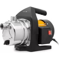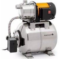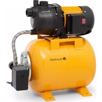
Liquidflow 800 - Pump Blumfeldt - Free user manual and instructions
Find the device manual for free Liquidflow 800 Blumfeldt in PDF.



User questions about Liquidflow 800 Blumfeldt
0 question about this device. Answer the ones you know or ask your own.
Ask a new question about this device
Download the instructions for your Pump in PDF format for free! Find your manual Liquidflow 800 - Blumfeldt and take your electronic device back in hand. On this page are published all the documents necessary for the use of your device. Liquidflow 800 by Blumfeldt.
USER MANUAL Liquidflow 800 Blumfeldt
natural_image
Abstract green circular logo with three curved segments (no text or symbols)
natural_image
Abstract green leaf-like graphic design with two curved leaves forming a triangular shape (no text or symbols)
natural_image
Abstract green circular logo with three leaf-like shapes forming a Y-shape (no text or symbols)Liquidflow 800
Liquidflow 1200 INOX Pro
Domestic Waterworks for Homte and Garden
text_image
QR code image containing encoded data, no visible human-readable textINHALT
natural_image
Symbol of a trash bin crossed with a diagonal line, no text or numbers presentCongratulations on purchasing this equipment. Please read this manual carefully and take care of the following hints to avoid damages. Any failure caused by ignoring the items and cautions mentioned in the instruction manual are not covered by our warranty and any liability. Scan the QR code to get access to the latest user manual and other information about the product.

text_image
QR code image containing encoded data, no visible human-readable textCONTENTS
Safety Instructions 10
Use 12
Disposal Considerations 14
Declaration of conformity 14
TECHNICAL DATA
| Item number 10034756 10034757 | ||
| Power supply 220-240 V ~ 50/60 Hz | ||
| Power | ||
| Qmax 3.2 m | ^3/h 3.7 m | ^3/h |
| Hmax 35 m 44 m | ||
| Work pressure 1.5 - 3 bar 1.5 - 3 bar | ||
| IP protection class x4 x4 | ||
| Dba <88 mm <88 mm | ||
| Diameter of pipe | 1" | 1" |
SAFETY INSTRUCTIONS
The appliance is designed for clean water with a temperature of max. 50 °C: any other use should be avoided.
When the maximum pump pressure is reached, the unit switches off the pump. However, there must be a pressure difference of at least 1.4 bar between switching on and off.
Children from the age of 8 years, people with mental, sensory or physical impairments may only use the unit if they have been thoroughly familiarised with the functions and safety precautions by a responsible supervisor and understand the risks involved.
Assembly
- Make sure that the system is installed flood-proof and sufficiently cooled with dry air.
- If the pump is mounted directly in the distribution network, it must be ensured that the inlet pressure is added to the pump pressure and that the total pressure does not exceed 10 bar.
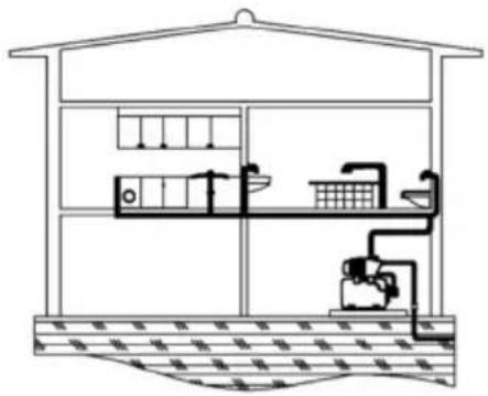
- The unit can be installed in an existing pipe / plant, provided that the minimum water requirement of the pump is always covered. Observe the installation diagrams.
Electrical connection
- Nominal current consumption of the pump must not exceed 10 (A) and the maximum power of the motor must not exceed 1.8 kW. A disconnecting device must be provided in the electrical installation, which allows disconnection from the mains with at least 3 mm contact opening for each pole. Pumps in alternating current design have an integrated motor protection switch. Pumps in three-phase design must be installed by the customer with an adjusted motor protection switch. We accept no liability for the consequences of improper installation, commissioning and improper electrical installation. The power cable must correspond to type H08 RN-F according to DIN VDE 0620.
- This diagram facilitates a correct mains connection.
- The system is secured by a differential switch (1 fn=30 mA)
- The power cable of the pump must at least correspond to H07 RN-R according to DIN VDE 0620 and be provided with cable lugs. The connection of the pump must be carried out by a qualified electrician.
CONNECTION SCHEME
natural_image
Cross-sectional diagram of a greenhouse or aquaculture facility showing water tanks, pipes, and a central storage unit (no text or labels)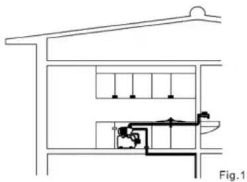
natural_image
Architectural cross-section diagram of a building facade with internal piping and structural elements (no text or labels)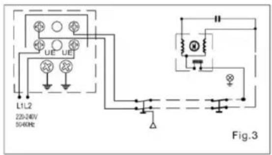
text_image
L1L2 225-240V/ 50-60Hz UE UE Fig.3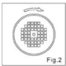
natural_image
Diagram showing a grid pattern inside a circle with an arrow indicating rotation (no text or symbols)USE
Controls prior to start up
Before fist starting ensure
- that the grid voltage and frequency match those featured on the specification plate.
• that the pump shaft turns freely. - that te pump body is completely full of water-fill by unscrewing the corresponding priming plug.
The pump .should never be operated dry.
Start-up
- Open all gate valves in the suction and discharge lines.
- Switch on the power and the pump will start automatically. Öffnen Sie alle eventuell vorhandenen Schieberventile in Druck- und Ansaugleitung.
- Stellen Sie den Hauptschalter auf EIN. Die Pumpe startet sofort. While doing so, leave the discharge tap open to bleed any air there may be in the system. Then close the tap and the assembly will shut down when it reaches maximum pump pressure.
- Verify the motor sense of rotating is clockwise, checked from the fan cover (fig 2).
- If the assembly does not operate, does not produce pressure or does not shut down, try to discover the cause of the problem consulting the troubleshooting guide provided below.
Maintenance
The unit does not require any specific maintenance. Notwithstanding, we recommend that they be emptied when temperatures are low and there is a risk of freezing or if the unit is not to be used for a long period of time. If the unit is not to be used for a very long period, it must be cleaned and stored in a dry, well-ventilated space.
TROUBLESHOOTING
| Problem Cause Solution | ||
| The unit does not shut down | Tap or cistern leak. Repair leak. | |
| Air entering suction channel. | Carefully seal all joints and connectors. | |
| Leak in discharge pipe-work. | Repair leak. | |
| The motor operates but provides no flow. | Closed gate valve. Open valve. | |
| Air entering suction channel. | Carefully seal all joints and connectors. | |
| The pressure is not sufficient. | Total head height. | Check geometric height plus loss of head. |
| Air entering suction channel. | Carefully seal all joints and connectors. | |
| Leak in discharge pipe-work. | Repair leak. | |
| The unit is constantly stopping and starting. | Tap or cistern leak. Repair leak. | |
| The unit does not start. | Plump block. Call service agent. | |
| No power. Check fuses. | ||
| The static head is greater than the assembly start pressure. | Check start-up setting is correct. | |
DISPOSAL CONSIDERATIONS
natural_image
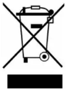
Symbol of a trash bin crossed with a diagonal line, no text or numbers presentAccording to the European waste regulation 2012/19/EU this symbol on the product or on its packaging indicates that this product may not be treated as household waste. Instead it should be taken to the appropriate collection point for the recycling of electrical and electronic equipment. By ensuring this product is disposed of correctly, you will help prevent potential negative consequences for the environment and human health, which could otherwise be caused by inappropriate waste handling of this product. For more detailed information about recycling of this product, please contact your local council or your household waste disposal service.
DECLARATION OF CONFORMITY
CE
Producer: Chal-Tec GmbH, Wallstraße 16, 10179 Berlin.
This product is conform to the following European Directives:
2011/65/EU (RoHS)
2014/30/EU (EMC)
2014/35/EU (LVD)
Chère cliente, cher client,
text_image
QR code image containing encoded data, no visible human-readable textSOMMAIRE
natural_image
Symbol of a trash bin crossed with a diagonal line, no text or numbers presentDÉCLARATION DE CONFORMITÉ
CE
Fabricant :
Chal-Tec GmbH, Wallstraße 16, 10179 Berlin, Allemagne.
text_image
QR code image containing encoded data, no visible human-readable textÍNDICE
natural_image
Symbol of a trash bin crossed with a diagonal line, no text or numbers presenttext_image
QR code image containing encoded data, no visible human-readable textINDICE
natural_image
Cross-sectional diagram of a greenhouse or aquaculture facility showing water tanks, irrigation pipes, and a worker (no text or labels)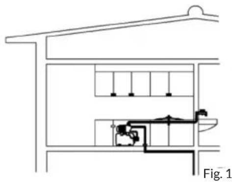
natural_image
Architectural cross-section diagram of a building facade with internal plumbing and ventilation systems (no text or labels)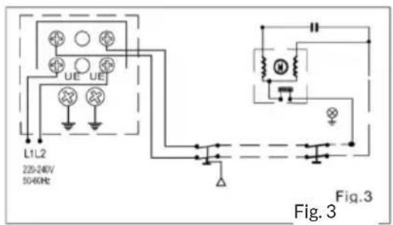
text_image
L1L2 225-240V 50-60Hz Fig. 3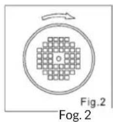
text_image
Fig.2 Fog. 2UTILIZZO
natural_image
Symbol of a trash bin crossed with a diagonal line, no text or numbers presentnatural_image
Abstract green circular logo with three curved segments (no text or symbols)
natural_image
Abstract green leaf-like graphic design with two triangular shapes (no text or symbols)