PGG 61 - Water pump Kärcher - Free user manual and instructions
Find the device manual for free PGG 61 Kärcher in PDF.
| Product type | Portable generator |
| Brand | Kärcher |
| Model | PGG 61 (series PGG 3/1, PGG 6/1, PGG 8/3) |
| Continuous output | 5.0 kW (PGG 6/1) |
| Maximum output (short-term) | 5.5 kW (PGG 6/1) |
| Output voltage | 230 V (single-phase) / 400 V (three-phase depending on model) |
| Frequency | 50 Hz (60 Hz for some versions) |
| Engine type | Single-cylinder, 4-stroke, air-cooled |
| Displacement | 389 cm³ (PGG 6/1) |
| Fuel | Unleaded gasoline, min. 86 octane |
| Fuel tank capacity | 25 L (PGG 6/1) |
| Runtime at 50% load | 10 h (PGG 6/1) |
| Engine oil | 10W-30 or 15W-40, quantity 1.1 L (PGG 6/1) |
| Battery | 12 V, for electric start |
| Dimensions (L x W x H) | 743 x 713 x 670 mm (PGG 6/1) |
| Weight (without fuel) | 85 kg (PGG 6/1) |
| Sound pressure level | 75 dB(A) (PGG 6/1) |
| Sound power level | 95 dB(A) (PGG 6/1) |
| Protection rating | IP23M |
| Main functions | Emergency power, construction site, leisure; 12 V battery charging |
| Routine maintenance | Check oil, air filter, spark plug, oil change, sediment cup |
| Warranty | According to country conditions, defects in material or workmanship |
| Spare parts | Original Kärcher accessories and parts available at www.kaercher.com |
| Safety | Circuit breaker, emergency stop, overload protection, key start |
Frequently Asked Questions - PGG 61 Kärcher
User questions about PGG 61 Kärcher
0 question about this device. Answer the ones you know or ask your own.
Ask a new question about this device
Download the instructions for your Water pump in PDF format for free! Find your manual PGG 61 - Kärcher and take your electronic device back in hand. On this page are published all the documents necessary for the use of your device. PGG 61 by Kärcher.
USER MANUAL PGG 61 Kärcher
natural_image
Exterior view of a Karcher portable electricity generator with visible battery, motors, and wiring (no text or symbols on main body)Deutsch 3
English 7
Français 11
Italiano 15
Nederlands 19
Español 23
Português 27
Dansk 31
Norsk 35
Svenska 39
Suomi 43
Ελληνικά 47
Türkçe 51
Русский 55
Magyar 60
Čeština 64
Slovenščina 68
Polski 72
Românește 77
Slovenčina 81
Hrvatski 85
Українська 89
中文 93
العربيئة 97
A
PGG 3/1
50 Hz
PGG 3/1
60 Hz

PGG 6/1
PGG 8/3
B
natural_image
Mechanical assembly diagram showing a component with numbered parts (1 and 2), no visible text or symbols.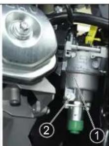
natural_image
Close-up of a mechanical assembly with labeled parts (1, 2), no visible text or symbols beyond labels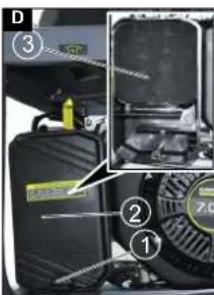
natural_image
Close-up of a mechanical assembly with visible components and wiring (no text or symbols)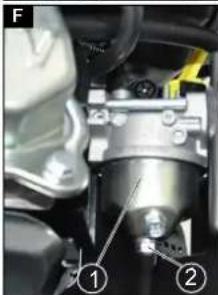
natural_image
Mechanical assembly diagram showing a motor and gear assembly (no text or labels visible)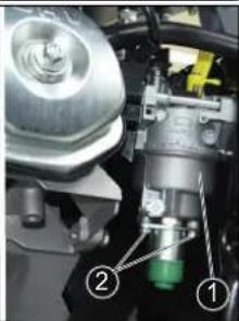
natural_image
Mechanical assembly diagram showing a valve and housing component (no text or labels visible)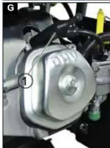
natural_image
Close-up of a mechanical component with labeled parts (no readable text or symbols)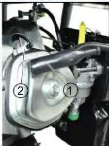
Inhalt
⚠️WARNUNG

H. Jenner
Chairman of the Board of Management

S. Reiser
Director Regulatory Affairs & Certification
71364 Winnenden (Germany)
Tel.: +49 7195 14-0
Fax: +49 7195 14-2212
Winnenden, 2018/10/01
Contents
General notes 7
Intended use 7
Environmental protection 7
Accessories and spare parts....7
Scope of delivery 7
Safety instructions....7
Device description....8
Installation....8
Initial start-up 8
Initial startup....8
Operation 8
Transport....9
Storage 9
Care and service....9
Troubleshooting guide.... 1
Warranty....1
Technical data.... 10
EU Declaration of Conformity 1
General notes

Read these original operating instructions and the enclosed safety instructions before using the device for the first
time. Proceed accordingly
Keep both books for future reference or for future owners.
Intended use
As delivered, this generator is intended for use at heights of up to 1500 m above sea level. It can be adjusted by an authorised Customer Service department for use at higher elevations.
If an electricity generator that has been adjusted for use at higher elevations is used below this height then this can result in destruction of the motor through overheating.
Environmental protection

The packing materials can be recycled. Please dispose of packaging in accordance with the environmental regulations.

Electrical and electronic appliances contain valuable, recyclable materials and often components such as batteries, rechargeable batteries or oil, which - if handled or disposed of incorrectly - can
pose a potential threat to human health and the environment. However, these components are required for the correct operation of the appliance. Appliances marked by this symbol are not allowed to be disposed of together with the household rubbish.
Notes on the content materials (REACH)
Current information on content materials can be found at: www.kaercher.com/REACH
Accessories and spare parts
Only use original accessories and original spare parts. They ensure that the appliance will run fault-free and safely.
Information on accessories and spare parts can be found at www.kaercher.com.
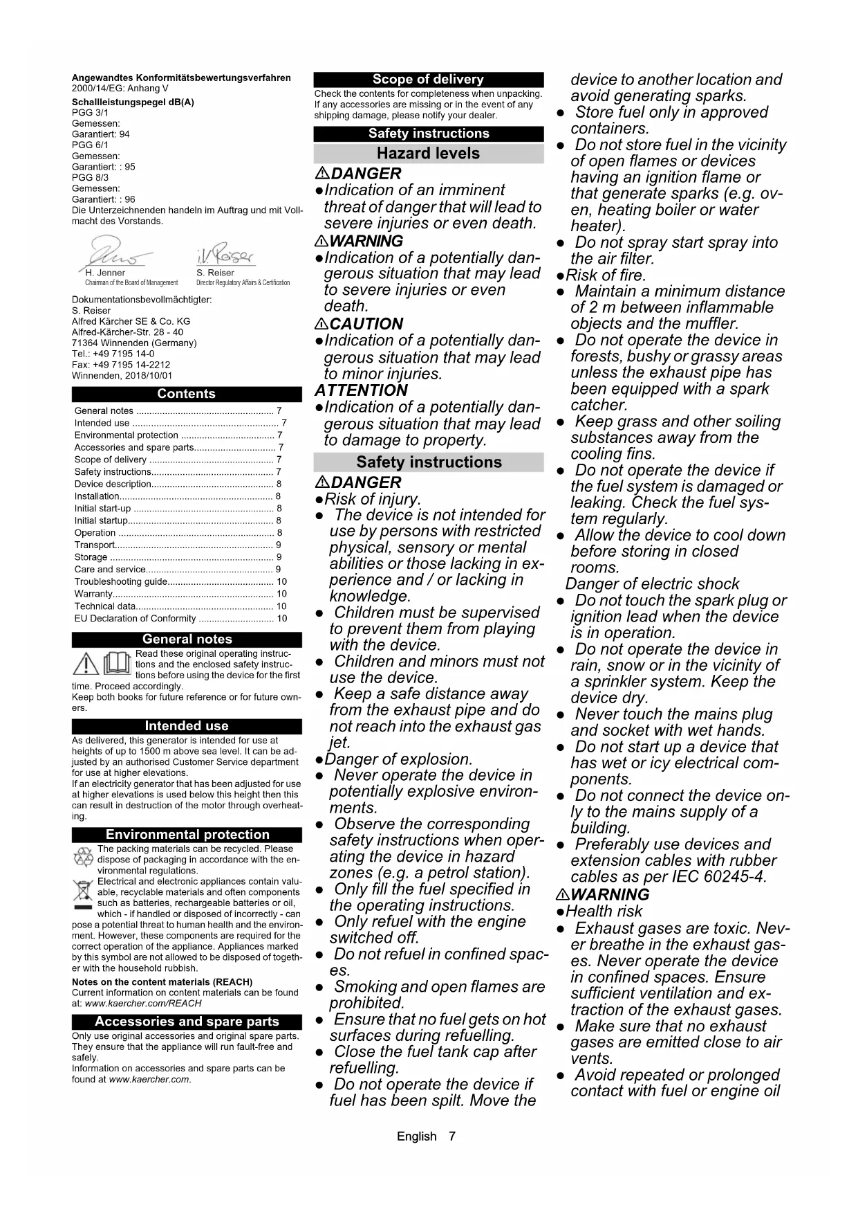
Scope of delivery
Check the contents for completeness when unpacking. If any accessories are missing or in the event of any shipping damage, please notify your dealer.
Safety instructions
Hazard levels
⚠️DANGER
- Indication of an imminent threat of danger that will lead to severe injuries or even death.
⚠ WARNING
- Indication of a potentially dangerous situation that may lead to severe injuries or even death.
△CAUTION
- Indication of a potentially dangerous situation that may lead to minor injuries.
ATTENTION
- Indication of a potentially dangerous situation that may lead to damage to property.
Safety instructions
⚠️DANGER
●Risk of injury.
- The device is not intended for use by persons with restricted physical, sensory or mental abilities or those lacking in experience and / or lacking in knowledge.
- Children must be supervised to prevent them from playing with the device.
- Children and minors must not use the device.
- Keep a safe distance away from the exhaust pipe and do not reach into the exhaust gas jet.
- Danger of explosion.
- Never operate the device in potentially explosive environments.
- Observe the corresponding safety instructions when operating the device in hazard zones (e.g. a petrol station).
- Only fill the fuel specified in the operating instructions.
- Only refuel with the engine switched off.
- Do not refuel in confined spaces.
- Smoking and open flames are prohibited.
- Ensure that no fuel gets on hot surfaces during refuelling.
- Close the fuel tank cap after refuelling.
- Do not operate the device if fuel has been spilt. Move the
device to another location and avoid generating sparks.
- Store fuel only in approved containers.
- Do not store fuel in the vicinity of open flames or devices having an ignition flame or that generate sparks (e.g. oven, heating boiler or water heater).
- Do not spray start spray into the air filter.
- Risk of fire.
- Maintain a minimum distance of 2 m between inflammable objects and the muffler.
- Do not operate the device in forests, bushy or grassy areas unless the exhaust pipe has been equipped with a spark catcher.
- Keep grass and other soiling substances away from the cooling fins.
- Do not operate the device if the fuel system is damaged or leaking. Check the fuel system regularly.
- Allow the device to cool down before storing in closed rooms.
Danger of electric shock
- Do not touch the spark plug or ignition lead when the device is in operation.
- Do not operate the device in rain, snow or in the vicinity of a sprinkler system. Keep the device dry.
- Never touch the mains plug and socket with wet hands.
- Do not start up a device that has wet or icy electrical components.
- Do not connect the device only to the mains supply of a building.
- Preferably use devices and extension cables with rubber cables as per IEC 60245-4.
⚠ WARNING
●Health risk
- Exhaust gases are toxic. Never breathe in the exhaust gases. Never operate the device in confined spaces. Ensure sufficient ventilation and extraction of the exhaust gases.
- Make sure that no exhaust gases are emitted close to air vents.
- Avoid repeated or prolonged contact with fuel or engine oil
and do not inhale the fuel va- pours.
△CAUTION
•Danger of burns
- Do not touch any hot parts such as the muffler, cylinder or cooling fins.
Danger of hearing damage
- Do not operate the device without a muffler. Check the muffler regularly and have a damaged muffler replaced.
ATTENTION
●Risk of damage
- Use only spare parts from the original manufacturer.
- Old fuel can lead to deposits in the carburettor and impair the engine performance. Use only new fuel.
- Do not adjust any control springs or linkages that might increase the speed of the engine.
- Do not operate the device with the air filter removed.
- Do not pull the starter cord while the device is running.
- Ensure adequate ventilation so that the device does not overheat.
Symbols on the device

△WARNING
Danger of explosion, risk of fire.
Petrol can cause fires or explosions if handled incorrectly.
Shut the motor down prior to refuelling.
Do not operate the device in confined spaces or partially enclosed areas.
Read these operating instructions before using the device.
ATTENTION
Risk of damage
Do not refuel with diesel fuel.
Note:
Check the oil level before starting the device. The engine stops and the indicator lamp lights up if the oil level is too low. Refill oil (for oil type see "Technical data").

△WARNING
Danger of explosion, risk of fire.
Shut the motor down prior to refuelling.
Clean up any spill fuel before starting the device.
Do not start the device if the fuel system is leaky.
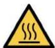
△CAUTION
Hot surface
The exhaust pipe of the device becomes very hot during operation and can cause burns.
Avoid touching the exhaust pipe.

△WARNING
Risk of eye injuries and hearing damage.
Wear safety goggles and hearing protection when operating the device.
Warning symbols
Observe the following warnings when handling the batteries:

Observe notes in the instructions for the battery, on the battery and in these operating instructions.

Wear eye protection.

Keep acids and batteries away from children.
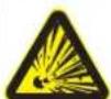
Risk of explosion
Fire, sparks, open flames and smoking are prohibited.
Risk of acid burns

First aid.

Warning

Disposal
Do not throw batteries in the bin.
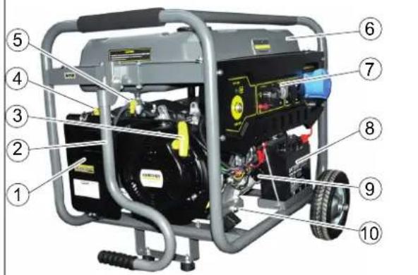
Device description
See cover page for pictures Illustration A
① Air filter
②Push handle
③ Starter cord
④ Choke lever
⑤ Fuel cock
⑥Fuel tank
⑦Control panel
⑧Battery
⑨ Oil dipstick
⑩Oil drain plug
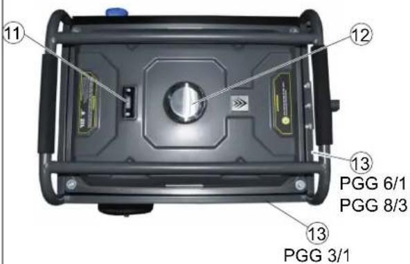
⑪ Fuel tank filling level display
⑫Fuel tank cap
⑬Type plate
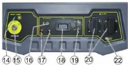
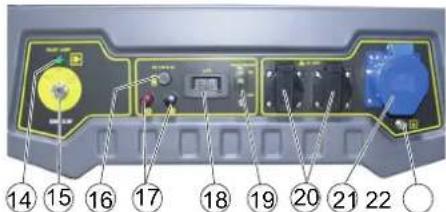
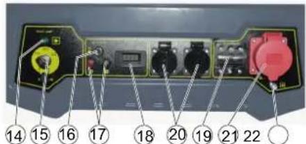
⑭Indicator lamp
⑮Engine key-operated switch
⑯DC circuit breaker
⑰DC terminals
⑱ AC voltmeter
⑲Power circuit breaker
⑳ AC power socket
(21) PGG 6/1: AC power socket
PGG 8/3: Three-phase socket
②2 Earthing terminal
Symbols on the device
AIR CLEANER MAINTENANCE
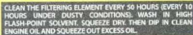
Clean the air filter every 50 operating hours or every 10 operating hours in the case of dusty environments(see "Care and maintenance/Cleaning the air filter").
Note on checking the oil level.

Choke lever
Installation
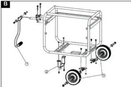
- Mount the push handle on the device frame using the mounting materials provided. Illustration B
① Push handle
② Stands
③Wheel
2. Mount the wheels on the device frame using the mounting materials provided.
3. Mount the stands on the device frame using the mounting materials provided.
Initial start-up
Fill with oil
- Position the device on a level surface.
- Unscrew the oil dipstick.
- Fill with engine oil.
Note: The engine oil is not included in the scope of delivery. The filling quantity and oil type are specified in the section "Technical data".
- Wipe off the oil dipstick
- Insert the oil dipstick as far as it will go, but do not screw in.
- Pull out the oil dipstick. The oil level must lie in the marked section of the oil dipstick.
- Top up the engine oil if the level is too low.
- Screw in and tighten the oil dipstick.
Initial startup
Check the oil level
- Position the device on a level surface.
- Unscrew the oil dipstick.
- Wipe off the oil dipstick.
- Insert the oil dipstick as far as it will go, but do not screw in.
- Pull out the oil dipstick. The oil level must lie in the marked section of the oil dipstick.
- Top up the engine oil if the level is too low.
- Screw in and tighten the oil dipstick.
Refuelling
- Read the fuel level indicator.
- Refill the fuel tank with the tank indicator shows a low filling level.
- Unscrew the fuel tank cap.
- Fill fuel up a maximum of the lower edge of the filling nozzle.
- Fit the fuel tank cap and screw tight.
Operation
Starting the device
- Open the fuel cock.
- Push the choke lever to the left if the engine is cold.
- Turn the key-operated switch to the START position and hold in this position until the engine starts. Hold the key-operated switch in the START position for no longer than 5 seconds. Wait for at least 10 seconds before attempting to start again.
- Allow the key-operated switch to return to the 1/ON position when the engine has started.
- Push the choke lever to the right once the engine has started.
Starting with the pull cord starter
- Open the fuel cock.
-
Push the choke lever to the left if the engine is cold.
-
Pull the starter cord slowly until a strong resistance is discernible then pull strongly.
-
Slowly return the starter cord.
ATTENTION
Risk of damage
A rapidly returning starter cord damages the device. Slowly return the starter cord.
- Push the choke lever to the right once the engine has started.
Connecting AC devices
The power consumption of the electrical device must not exceed the continuous power rating of the generator. The maximum power may only be used for brief periods. Devices with electric motors require several times the nominal power when starting up.
△DANGER
Danger of electric shock
Electricity can flow through the operator and cause death or injuries if the electrical equipment or cables are damaged.
A fault current protection device (PRCD Portable Residual Current Device) must be connected between each additional device and the generator if more than one device is plugged into the generator.
- Start the generator.
- Set the power switch to 1/ON.
- Plug the mains plug of the electrical device into the socket of the generator.
- A fault current protection device (PRCD Portable Residual Current Device) must be connected between each additional device and the generator if more than one device is plugged into the generator.
- Start the electrical device.
If the device does not function correctly, e.g. irregular running or misfires, immediately switch off and unplug the connected appliances and investigate the cause.
Charging vehicle batteries
The 12 V DC connection is only suitable for charging 12 V lead-acid automobile batteries. This connection is not suitable for use as a 12 V power supply for electrical appliances.
- Disconnect the vehicle minus cable (black) from the battery.
- Connect the plus terminal (red) of the charging cable to the plus terminal of the battery.
- Connect the plus terminal (red) of the other end of the charging cable to the red terminal (+) of the generator.
- Connect the minus terminal (black) of the charging cable to the minus terminal of the battery.
- Connect the minus terminal (black) of the other end of the charging cable to the black terminal (-) of the generator.
- Start the generator.
ATTENTION
Risk of damage.
The vehicle or generator can be damaged during charging if the vehicle engine is running while charging the vehicle battery.
Do not start the vehicle while charging the battery.
Circuit breaker
The circuit breaker button pops out and interrupts charging if an overload occurs.
- Wait a few minutes and then press the button in again.
Disconnect the vehicle battery
- Shut down the generator.
- Disconnect the minus pole (black) from the generator.
- Disconnect the minus terminal (black) from the battery.
- Disconnect the plus pole (red) from the generator.
- Disconnect the plus terminal (red) from the battery
- Connect the vehicle minus cable (black) to the minus pole of the battery.
Switching off the device
-
Turn the key-operated switch to "0/OFF".
-
Close the fuel cock.
Transport
- Turn the key-operated switch to 0/OFF and close the fuel cock before transport.
- Push the push handle upwards.
- Push or pull the device using the push handle.
- Allow the engine to cool down for at least 15 minutes before loading.
- Keep the device horizontal during transport to prevent fuel from spilling out.
- When transporting in vehicles, secure the device against rolling away, slipping and tipping according to the respectively applicable guidelines.
- Be aware of the weight of the device during transport.
Storage
△CAUTION
Failure to observe the weight
Risk of injury and damage
Be aware of the weight of the device during storage.
ATTENTION
Risk of damage
Do not place any heavy objects on the device.
Store the device in a dry and dust-free place.
Storage duration of 1...2 months
-
Add petrol stabiliser to the fuel tank.
-
Top up the fuel tank.
Storage duration of 2...12 months
Additionally:
-
Close the fuel cock.
-
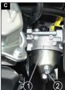
Place a container under the carburettor.
Illustration C
①Carburettor
②Drain screw
- Unscrew the drain screw.
- Collect the fuel in the container.
- Screw in and tighten the drain screw.
- Empty the settling cup (see "Care and Maintenance/Cleaning the settling cup").
Storage duration longer than 12 months
Additionally:
- Unscrew the spark plug.
- 5...10 cm ^3 Add engine oil to the cylinder.
- Slowly pull the starter cord several times to distribute the oil in the engine.
- Screw in the spark plug.
- Change the oil (see "Care and Maintenance/Changing the oil").
- Pull the starter cord slowly until a strong resistance is discernible.
Care and service
△DANGER
Danger of injury from electric shock.
You can be injured by moving parts. The electrical voltage generated by the device can kill or injure you. Remove the spark plug connector and disconnect the battery before performing any maintenance work.
△CAUTION
Danger of burns.
Hot device components cause burns if touched. Allow the device to cool down before working on it. * See "Startup" for a description.
** See "Maintenance work" for a description.
Maintenance intervals
Each time before use
- Check the device for correct condition and operational safety. Do not start up a damaged device.
- Check the oil level. *
- Check the air filter. **
Once after 1 month or 20 operating hours
- Change the oil. **
Every 3 months or 50 operating hours
- Clean the air filter. **
Perform cleaning more frequently in a dusty application environment.
Every 6 months or 100 operating hours
- Change the oil. **
- Clean the settling cup. **
- Check and clean the spark plug. **
- Clean the spark catcher (not included in the scope of delivery). **
Annually by the authorised Customer Service
department
- Check and adjust the valve play.
- Clean the fuel tank and fuel filter.
Every 2 years by the authorised Customer Service
department
- Check the fuel line and replace if necessary.
Maintenance work
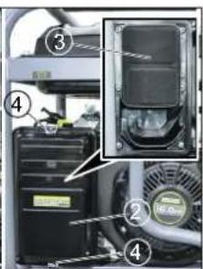
Check the air filter
- Pivot the lock away or unscrew the screw. Illustration D
① Screw
② Cover
③ Air filter insert
④Lock
- Remove the cover.
- Check the air filter insert for soiling. Clean the air filter if necessary or replace if damaged (see "Cleaning the air filter").
- Fit the cover
- Close the lock or screw in and tighten the screw.
Cleaning the air filter
ATTENTION
Risk of damage
Penetrating dust can destroy the engine if the air filter insert is absent.
Do not operate the device without an air filter insert.
1. Open the air filter (see "Checking the air filter").
2. Remove the air filter insert.
3. Wash the air filter insert in warm water and household cleaner then rinse with clear water.
Note: Dispose of the oil contaminated washing solution in an environmentally friendly manner.
4. Allow the air filter insert to dry.
5. Saturate the air filter insert in clean engine oil and press out the excess oil.
6. Fit the air filter insert back into place.
7. Fit the cover
8. Close the latches.
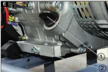
Changing oil
Perform the oil change on a warm engine.
- Unscrew the oil dipstick.
Illustration E
① Oil dipstick
②Oil drain plug
- Unscrew the oil drain screw with seal and catch the escaping oil.
- Screw in and tighten the oil drain screw with seal.
- Position the device on a level surface.
- Measure the correct quantity of engine oil (for oil type see "Technical data") and fill through the oil dipstick hole.
- Check the oil level (see "Starting up").
- Screw in and tighten the oil dipstick.
- Dispose of the old oil in accordance with the environmental regulations.
Cleaning the settling cup
The settling cup separates water from the petrol.
-
Close the fuel cock.
-
Unscrew the settling cup.
Illustration F
① Settling cup
② Screw
3. Remove the settling cup with O-ring.
4. Clean the settling cup and O-ring using a non-inflammable solvent and allow to dry.
5. Fit the settling cup and O-ring and screw tight.
6. Open the fuel cock.
7. Check the seal between the settling cup and carburettor.
8. Close the fuel cock.
Checking and cleaning the spark plug
- Pull off the spark plug connector. Illustration G
① Spark plug connector
② Spark plug
2. Clean the region around the spark plug to prevent dirt from entering the engine when the spark plug is removed.
3. Unscrew the spark plug.
4. Replace a spark plug that has worn electrodes or a broken insulator.
5. Check the electrode gap of the spark plug. Target value 0.7...0.8 mm.
6. Check the spark plug seal for damage.
ATTENTION
Risk of damage
A loose spark plug can overheat and damage the engine. An overtightened spark plug can damage the thread in the engine.
Observe the following instructions for tightening the spark plug.
- Carefully screw the spark plug in by hand. Do not cross the thread.
- Screw the spark plug all the way in using the plug spanner and the tighten as follows.
a Tighten a used spark plug by an additional 1/8...1/4 turn.
b Tighten a new spark plug by an additional 1/2 turn.
- Plug on the spark plug connector.
Charging the device battery
△DANGER
Danger of explosion, risk of fire
Connecting the two battery terminals causes a short-circuit that can result in an explosion or fire.
Never place a metal object (e.g. a tool) on the battery.
Danger of injury
Observe the safety instructions on the handling of batteries.
Observe the operating instructions for the charger.
△CAUTION
Health risk
Lead is harmful to your health.
Never allow lead to come into contact with open wounds.
-
Check the battery acid level.
-
If the battery acid level is too low:
a Remove the cell cap.
b Top up the cell with distilled water up to the marking.
c Fit the cell cap.
-
Disconnect the battery.
-
Connect the plus cable of the charger to the plus terminal of the battery.
-
Connect the minus cable of the charger to the minus terminal of the battery.
-
Switch on the charger.
Troubleshooting guide
Have all checks and work on electrical parts performed by an expert.
In case of any malfunctions not mentioned in this chapter, contact the authorised Customer Service.
The engine does not start.
-
Open the fuel cock.
-
Fill the tank with fuel.
-
Check the oil level and top up if necessary.
-
Check the spark plug (see "Care and maintenance/ Checking and cleaning the spark plug").
-
Clean the settling cup (see "Care and Maintenance/Cleaning the settling cup").
The device does not generate any electricity
- Set the power switch to 1/ON.
Warranty
The warranty conditions issued by our relevant sales company apply in all countries. We shall remedy possible malfunctions on your appliance within the warranty period free of cost, provided that a material or manufacturing defect is the cause. In a warranty case, please contact your dealer (with the purchase receipt) or the next authorised customer service site.
(See overleaf for the address)
Technical data
| PGG 3/1 50 Hz PGG 3/1 60 Hz PGG 6/1 PGG 8/3 | |||||
| Generator | |||||
| Continuous output kW 2,8 2,8 5,0 7,0 | |||||
| Maximum short-term output kW 3,0 3,0 5,5 7,5 | |||||
| cos φ | 1 | 1 | 1 | 1 | |
| Mains voltage | V | 230 (2x) | 220 (2x) | 230 (3x) | 230 (2x), 400 (1x) |
| Phase | ~ | 1 | 1 | 1 | 1 / 3 |
| Frequency | Hz | 50 | 60 | 50 | 50 |
| Degree of protection | IP23M | IP23M | IP23M | IP23M | |
| Insulation class | B | B | B | B | |
| Design class | G1 | G1 | G1 | G1 | |
| DC output | |||||
| Voltage | V | 12 | 12 | 12 | 12 |
| current | A | 6 | 6 | 6 | 6 |
| Internal combustion engine | |||||
| Engine type | Single-cylinder | Single-cylinder | Single-cylinder | Single-cylinder | |
| Type | 4-stroke | 4-stroke | 4-stroke | 4-stroke | |
| Cooling type | Air-cooled | Air-cooled | Air-cooled | Air-cooled | |
| Engine capacity | cm^3 | 208 | 208 | 389 | 439 |
| Engine performance | kW/PS | 5,1/6,9 | 5,1/6,9 | 9,6/13,1 | 11,8/16,1 |
| Fuel type | Petrol, min. 86 oc-tane | Petrol, min. 86 oc-tane | Petrol, min. 86 oc-tane | Petrol, min. 86 oc-tane | |
| Fuel tank capacity | 15 | 15 | 25 | 25 | |
| Working time with full tank, 100% performance | h | 6,5 6,5 6,5 5,5 | |||
| Working time with full tank, 50% performance | h | 12 | 12 | 10 | 7 |
| Engine oil volume | I | 0,6 0,6 1,1 1,1 | |||
| Oil type | 10 W-30 | 10 W-30 | 10 W-30 | 10 W-30 | |
| 15 W-40 | 15 W-40 | 15 W-40 | 15 W-40 | ||
| Spark plug type | F5T, F6T, F7TJC | F5T, F6T, F7TJC | F5T, F6T, F7TJC | F5T, F6T, F7TJC | |
| Battery | |||||
| Working voltage of the battery | V | 12 | 12 | 12 | 12 |
| Dimensions and weights | |||||
| Length | mm | 645 | 645 | 743 | 743 |
| Width | mm | 622 | 622 | 713 | 713 |
| Height | mm | 559 | 559 | 670 | 670 |
| Weight without fuel | kg | 52 | 52 | 85 | 90 |
| Determined values in acc. with EN 60335-2-79 | |||||
| Sound pressure level L_pA | dB(A) | 74 | 74 | 75 | 76 |
| Uncertainty K_pA | dB(A) | 1 | 1 | 1 | 1 |
| Sound power level L_WA + K uncertainty _WA | dB(A) | 94 | 94 | 95 | 96 |
| CO2Emissions according to the measurement procedure of EU regulation 2016/1628 Euro V | |||||
| Motor | g/kWh | 790 678 | 678 | ||
Subject to technical modifications.
EU Declaration of Conformity
We hereby declare that the machine described below complies with the relevant basic safety and health requirements in the EU Directives, both in its basic design and construction as well as in the version placed in circulation by us. This declaration is invalidated by any changes made to the machine that are not approved by us.
Product: Power generator
Type: 1.042-xxx
Currently applicable EU Directives
2006/42/EC (+2009/127/EC)
2014/30/EU
2011/65/EU
2000/14/EC
Harmonised standards used
EN ISO 8528-13: 2016
EN 55012: 2007 + A1: 2009
EN 61000-6-1: 2007
Conformity evaluation procedure used
2000/14/EC: Appendix V
Sound power level dB(A)
PGG 3/1
Measured:
Guaranteed: 94
PGG 6/1
Measured:
Guaranteed: : 95
PGG 8/3
Measured:
Guaranteed: : 96
The undersigned act on behalf and under the power of attorney of the company management.

H. Jenner
Chairman of the Board of Management

S. Reiser
Director Regulatory Affairs & Certification
Documentation supervisor:
S. Reiser
Alfred Kärcher SE & Co. KG
Alfred-Kärcher-Str. 28 - 40
71364 Winnenden (Germany)
Ph.: +49 7195 14-0
Fax: +49 7195 14-2212
Winnenden, 2018/10/01
Contenu
△AVERTISSEMENT
2006/42/CE (+2009/127/CE)
2014/30/UE
2011/65/EU
2000/14/CE

Chairman of the Board of Management

S. Reiser
Director Regulatory Affairs & Certification
71364 Winnenden (Germany)
△AVVERTIMENTO

H. Jenner
Chairman of the Board of Management

S. Reiser
Director Regulatory Affairs & Certification
71364 Winnenden (Germany)
Tel.: +49 7195 14-0
Fax: +49 7195 14-2212
Winnenden, 01/10/2018
Inhoud
△WAARSCHUWING

H. Jenner
Chairman of the Board of Management

S. Reiser
Director Regulatory Affairs & Certification
71364 Winnenden (Germany)
Tel.: +49 7195 14-0
Fax: +49 7195 14-2212
Winnenden, 2018/10/01
ADVERTENCIA
2006/42/CE (+2009/127/CE)
2014/30/UE
2011/65/UE
2000/14/CE
71364 Winnenden (Germany)
Tel.: +49 7195 14-0
Fax: +49 7195 14-2212
Winnenden, 01/10/2018
Indice
ATENÇÃO
2006/42/CE (+2009/127/CE)
2014/30/UE
2011/65/UE
2000/14/CE

H. Jenner
Chairman of the Board of Management

S. Reisen
Director Regulatory Affairs & Certification
Winnenden, 01/10/2018
Indhold
ADVARSEL
Eksplosionsfare, brandfare.
2006/42/EF (+2009/127/EF)
2014/30/EU
2011/65/EU
2000/14/EF

H. Jenner
Chairman of the Board of Management

S. Reiser
Director Regulatory Affairs & Certification
71364 Winnenden (Germany)
Tlf.: +49 7195 14-0
Fax: +49 7195 14-2212
Winnenden, 2018/10/01
Indhold
ADVARSEL
⑯Nøkkelbryter likestrøm
⑰Klemmer likestrøm
⑱Voltmeter vekselspenning
⑲Effektbryter
2006/42/EF (+2009/127/EF)
2014/30/EU
2011/65/EU
2000/14/EF
Anvendte harmoniserte standarder
EN ISO 8528-13: 2016
EN 55012: 2007 + A1: 2009
EN 61000-6-1: 2007
2000/14/EF: Vedlegg V
Lydeffektnivå dB(A)
PGG 3/1
Målt:
Garantert: 94
PGG 6/1
Målt:
Garantert: : 95
PGG 8/3
Målt:
Garantert: : 96

Chairman of the Board of Management

S. Reiser
Director Regulatory Affairs & Certification
71364 Winnenden (Germany)
Tlf.: +49 7195 14-0
Winnenden, 10/01/2018
Innehåll
Allmän information 39
△VARNING

H. Jenner
Chairman of the Board of Management

S. Reiser
Director Regulatory Affairs & Certification
D-71364 Winnenden (Germany)
Tfn: +49 7195 14-0
Fax: +49 7195 14-2212
Winnenden, 2018/10/01
Sisältö
△VAROITUS

H. Jenner
Chairman of the Board of Management

S. Reiser
Director Regulatory Affairs & Certification
71364 Winnenden (Germany)
Puh.: +49 7195 14-0
Winnenden, 2018/10/01
Περιεχόμενα
ΔΠΡΟΕΙΔΟΠΟΙΗΣΗ

H. Jenner
Chairman of the Board of Management

S. Reisen
Director Regulatory Affairs & Certification
71364 Winnenden (Germany)
Tηλ.: +49 7195 14-0
Φαξ: +49 7195 14-2212
Winnenden, 2018/10/01
İçindekiler
⚠UYARI
ENGINE OIL AND SQUEEZE OUT EXCESS OIL
2006/42/AT (+2009/127/AT)
2014/30/AB
2011/65/AT
2000/14/EG

H. Jenner
Chairman of the Board of Management

S. Reiser
Director Regulatory Affairs & Certification
Winnenden, 2018/10/01
Содержание
Общие указания 55
⚠ПРЕДУПРЕЖДЕНИЕ

H. Jenner
Chairman of the Board of Management

S. Reiser
Director Regulatory Affairs & Certification
71364 Winnenden (Germany)
Тел.: +49 7195 14-0
Факс: +49 7195 14-2212
△FIGYELMEZTETÉS

H. Jenner
Chairman of the Board of Management

S. Reiser
Director Regulatory Affairs & Certification
Winnenden, 2018/10/01
Obsah
Obecné pokyny 64
⚠VAROVÁNÍ
2006/42/ES (+2009/127/ES)
2014/30/EU
2011/65
2000/14/ES

H. Jenner
Chairman of the Board of Management
S. Reiser
Director Regulatory Affairs & Certification
Winnenden, 2018/10/01
Kazalo
Splošna navodila.... 68
Namenska uporaba.... 68
Varovanje okolja.... 68
Pribor in nadomestni deli 69
Obseg dobave.... 69
Varnostna navodila.... 69
Opis naprave.... 70
Montaža 70
Prvi zagon 70
Zagon.... 70
Obratovanje 70
Transport.... 71
Skladiščenje 71
△OPOZORILO
Nevarnost eksplozije, požara.
(PRCD-Portable Residue Current Device).
2006/42/ES (+2009/127/ES)
2014/30/EU
2011/65/EU
2000/14/ES

H. Jennifer
Chairman of the Board of Management

S. Reiser
Director Regulatory Affairs & Certification
⚠OSTRZEŻENIE
2006/42/WE (+2009/127/WE)
2014/30/UE
2011/65/UE
2000/14/WE

H. Jenner
Chairman of the Board of Management

S. Reiser
Director Regulatory Affairs & Certification
71364 Winnenden (Germany)
Tel.: +49 7195 14-0
Winnenden, 2018/10/01
Cuprins
△AVERTIZARE
Pericol de explozie, pericol de incendiu.
Directive UE relevante
2006/42/UE (+2009/127/UE)
2014/30/UE
2011/65/UE
2000/14/UE
Norme armonizate aplicate
EN ISO 8528-13: 2016
EN 55012: 2007 + A1: 2009
EN 61000-6-1: 2007

H. Jenner
Chairman of the Board of Management

S. Reiser
Director Regulatory Affairs & Certification
71364 Winnenden (Germania)
Tel.: +49 7195 14-0
Fax: +49 7195 14-2212
Winnenden, 01.10.2018
Obsah
ΔVÝSTRAHA
2006/42/ES (+2009/127/ES)
2014/30/EÚ
2011/65/EÚ
2000/14/ES

H. Jenner
Chairman of the Board of Management

S. Reiser
Director Regulatory Affairs & Certification
www.kaercher.com/REACH
⚠UPOZORENJE
2006/42/EZ (+2009/127/EZ)
2014/30/EU
2011/65/EU
2000/14/EZ

H. Jenner
Chairman of the Board of Management

S. Reiser
Director Regulatory Affairs & Certification
Opunomoćenik za dokumentaciju:
S. Reiser
Alfred Kärcher SE & Co. KG
Alfred-Kärcher-Str. 28 - 40
71364 Winnenden (Njemačka)
Tel.: +49 7195 14-0
Telefaks: +49 7195 14-2212
Winnenden, 1. 10. 2018.
3MICT
△ПОПЕРЕДЖЕННЯ

H. Jenner
Chairman of the Board of Management

S. Reiser
Director Regulatory Affairs & Certification
71364 Winnenden (Germany)
Тел.: +49 7195 14-0
Факс: +49 7195 14-2212
www.kaercher.com/REACH
附件和备件
| WARNING |
| CHECK FUEL LEVER, THE GENERATOR WILL STOP AUTOMATICALLY WHEN THE OIL IS TOO LOW, AND THE INDICATOR LIGHT WILL BE ON. |
| Read Decorry Manual before operating. |
| Experiences feel able to use fire and prevent burns. |
| Handed up above or in the partly compressed frame. |
| Stop engine poison lying flat near. |
| Fillet recommended level with snow TOWES. |
警告
爆炸危险、起火危险。
.(Residue Current Device
- retirement méditerrane del refondissement Majorities of the Turkish government
الجهاز
B صورة إيضاحية
① مقبض الدفع
② سنادات
عجلة ③
natural_image
Black and white line drawing of a hand giving a thumbs-up gesture (no text or symbols)THANK YOU!
MERCI! DANKE! iGRACIAS!

Register your product and benefit from many advantages.
www.kaercher.com/welcome


Rate your product and tell us your opinion.
natural_image
Icon showing a gear and wrench inside a square frame (no text or symbols)www.kaercher.com/dealersearch
Alfred Kärcher SE & Co. KG
Alfred-Kärcher-Str. 28-40
71364 Winnenden (Germany)
Tel.: +49 7195 14-0
Fax: +49 7195 14-2212