Independ 3100 - Generator Eurom - Free user manual and instructions
Find the device manual for free Independ 3100 Eurom in PDF.



| Brand | Eurom |
| Model | Independ 3100 |
| Category | Generator |
| Type | Inverter |
| AC output voltage | 230 V - 50 Hz |
| Maximum capacity | 3.1 kVA |
| Continuous capacity | 2.6 kVA |
| Power factor | 1.0 |
| DC output | 12 V / 8.3 A |
| Engine | SY157F, 4-stroke, air-cooled |
| Displacement | 149.5 cm³ |
| Max engine power | 4 kW at 5500 rpm |
| Fuel | Unleaded gasoline |
| Fuel tank capacity | 5.7 liters |
| Engine oil | SAE 10W30/40, 0.9 liter |
| Starting system | Recoil starter |
| Spark plug | A7RTC, gap 0.6-0.7 mm |
| Dimensions (L×W×H) | 565 × 320 × 470 mm |
| Net weight | 29 kg |
| Autonomy at full load | 3 hours |
| Safety | Automatic low oil shutdown, overload protection, DC protection |
Frequently Asked Questions - Independ 3100 Eurom
User questions about Independ 3100 Eurom
0 question about this device. Answer the ones you know or ask your own.
Ask a new question about this device
Download the instructions for your Generator in PDF format for free! Find your manual Independ 3100 - Eurom and take your electronic device back in hand. On this page are published all the documents necessary for the use of your device. Independ 3100 by Eurom.
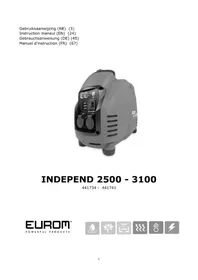
USER MANUAL Independ 3100 Eurom
Instruction manaul (EN) (24)
natural_image
Exterior view of a gray electric shock absorber device (no visible text or symbols)INDEPEND 2500 - 3100
441734 - 441741
Dank
natural_image
Line drawing of a portable vacuum cleaner with attached circuit board and power cord (no text or symbols)Brandgevaar
- Economy-schakelaar (ECON)
- Motorschakelaar (ENG.SW.)
- Brandstoftank
- Bougiedeksel
- Uitlaat
- Draaghandgreep
- Choke-hendel
- Controlelampje AC 230V\~(OUTPUT)
- Lamp overbelasting (OVERLOAD)
-
Lamp olie alarm (OIL ALERT) oil alert)
-
Stopcontact AC 230V\~ (2x)
- Stopcontact DC 12V=
- Aardingspunt
- Brandstofffilter
- Tankdop
- Trekstarter
- Brandstofkraan
- Olievuldop
- Luchtfilter
2 - Motorschakelaar (ENG.SW)
natural_image
Two-step diagram showing a mechanical device with a downward arrow and a hand holding a circular component (no text or symbols)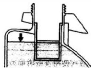
natural_image
Illustration of a hand holding a small object over a circular base (no text or symbols)Waarschuwing:
3 - Aarding
natural_image
Line drawing of a portable electricity cooker with attached circuit board and power cord (no text or symbols)Werking
Let op:
natural_image
Line drawing of a portable air purifier with attached plug (no text or symbols)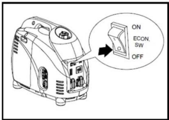

natural_image
Line drawing of a portable air conditioner unit with a highlighted ON/OFF button (no text or symbols on the device itself)e) Zet de motorschakelaar in de "ON"-stand (AAN)
natural_image
Line drawing of a portable air conditioner unit with a hand pulling the cable (no text or symbols)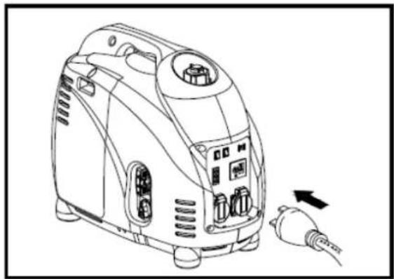
natural_image
Line drawing of a portable air purifier with attached plug and control panel (no text or symbols)natural_image
Line drawing of a portable air conditioner unit with a screwdriver inserted, showing airflow direction (no text or symbols)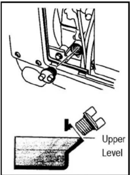
3 - Luchtfilter
flowchart
graph TD
    A["Feed Pump"] --> B["Reinjection Tank"]
    B --> C["Water Dish with Drying"]
    C --> D["Heating Toward Down"]
    D --> E["Clean Water Cover"]
    E --> F["Exhausting Cover"]
    F --> G["Discharge to Cover Sheet"]
    G --> H["Toxic Discharge"]
natural_image
Technical line drawings of a vacuum cleaner and its internal components, including a valve assembly and threaded screw (no text or symbols)5 - Filter brandstoftank
6 - vonkenvanger
Waarschuwing:
Problemen oplossen
natural_image
Simple line drawing of a trash bin with diagonal lines crossing it, no text or symbols present.Thank you for selecting a EUROM device. You have made a good choice! We hope that you are completely satisfied with your purchase. To get the most out of your device, it is important that you read this manual carefully in its entirety and understand it before use. Pay close attention to the safety regulations; they are given to protect you and your environment!
Ensure you keep the manual for future reference. Do not throw away the packaging: it is the best protection you can give to your device while storing it out of season. Should you wish to give the device to someone else, give the manual and packaging with it.
We hope you enjoy using your generator!
Eurom
Kokosstraat 20
8281 JC Genemuiden (NL)
info@eurom.nl
www.eurom.nl
This manual has been written with the utmost care. Nevertheless, we reserve the right to optimise this manual and change it technically at any time. The images used may deviate from the supplied product.
Symbols used

The Eurom generator has been designed such that it is safe and reliable when used correctly. Study this manual before using the generator. Failure to do so may lead to personal injury or damage to the equipment.
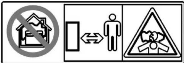
- Exhaust fumes contain toxic carbon monoxide – a gas that is colourless and odourless. Inhaling carbon monoxide can cause loss of consciousness and may result in death.
- If you operate the generator in a (partially) closed area, the amount of toxic exhaust fumes in the air may become dangerous.
- Never run the generator in a garage, residence or the vicinity of open windows or doors.
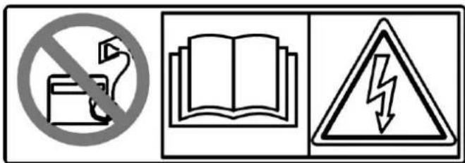
- Do not connect the generator to the main power grid.
- Do not connect the generator in parallel with another generator.
- An incorrect connection could supply electricity to the power grid through the building's electrical system. This means that there is a possibility that people working on the grid could be electrocuted and, once power is applied to the grid again, the generator could explode, burst into flames or cause a fire. Consult the electricity company or a recognised electrician prior to making any electrical connections.

The device contains hot components that could cause serious burns. Avoid contact during and after the engine has been on.
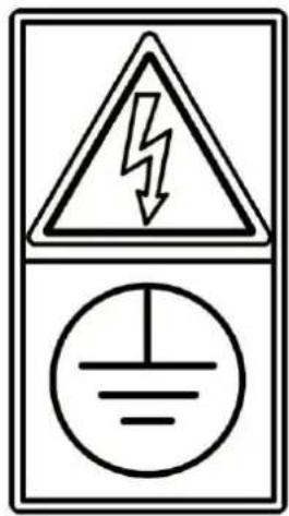
Before starting the engine, the generator must be earthed to prevent electric shocks in case of a fault.
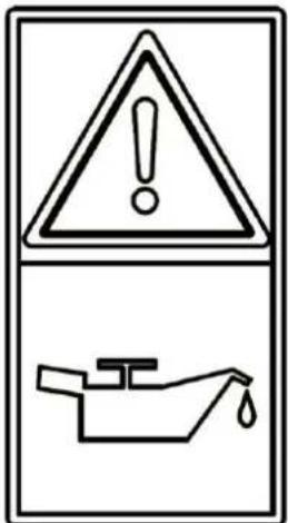
Using the generator with little or no oil in the crankcase could damage the engine.

Be careful! When switching the generator off, the engine will continue to run for a few seconds.
Technical data
| MODEL | Independ 2500 | Independ 3100 |
| Type | Inverter | Inverter |
| AC voltage | 230 V – 50 Hz | 230 V – 50 Hz |
| Max. capacity | 2.4 kVA | 3,1 kVA |
| Continuous capacity | 2.2 kVA | 2.6 kVA |
| Power factor | 1.0 | 1.0 |
| DC capacity | 12 V / 8,3A | 12 V / 8,3A |
| Model | SY152F-3 | SY157F |
| Type | Air-cooled, 4-stroke, OHV, petrol engine | Air-cooled, 4-stroke, OHV, petrol engine |
| Cylinder capacity | 124.6 CC | 49.5 CC |
| Max. capacity | 3.5 kW – 5500 t.p.m. | 4 kW – 5500 t.p.m. |
| Fuel | Unleaded petrol | Unleaded petrol |
| Fuel tank capacity | 5.7 litres | 5.7 litres |
| Continuous operation | 4.2 hours (at 100%) | 3 hours (at 100%) |
| Engine oil | SAE 10W30/40 | SAE 10W30/40 |
| Oil tank capacity | 0.9 litres | 0.9 litres |
| Starting system | Recoil starter | Recoil starter |
| Ignition system | C.D.I. | C.D.I. |
| Spark plug type | A7RTC | A7RTC |
| Net dimensions | 565 x 320 x 470 mm | 565 x 320 x 470 mm |
| Net weight | 28 kg | 29 kg |
Safety information
WARNING: If the instructions given are not followed, there is a danger of serious personal injury or even a fatal accident.
CAUTION: If the instructions given are not followed, there is a danger of serious personal injury or serious damage to the machinery.
IMPORTANT SAFETY REGULATIONS
Eurom generators are designed to be used with electrical equipment with a suitable power requirement. Incorrect use may cause personal injury or damage to the generator or other objects. By following the instructions in this instruction booklet and on the generator, the possibility of injury or damage is minimised. The most important risks and safety measures are discussed below. Never attempt to made changes to the generator. This could lead to accidents or damage to the generator and equipment connected to it.
User responsibility
Make sure that you know how to switch the generator off quickly in emergencies. Ensure that you are aware of all options for operation and connections. Ensure that everyone who operates the generator receives the correct instructions. Do not allow the generator to be operated by children without appropriate supervision. Consult the instructions in this manual for the use and maintenance of the generator. Not following the instructions or following them incorrectly could lead to accidents such as electrical shock and an increase in harmful exhaust fumes. Observe the legislation and regulations that apply to the location where the generator is being used. Petrol and oil are toxic. For use, follow the instructions of the relevant manufacturer. Before use, place the generator on a sturdy, flat surface. Do not open any covers while operating the generator. This could lead to accidents or limbs becoming trapped. Consult your Eurom dealer for disassembly or maintenance work that is not discussed in this manual.
A generator can create hazards that are not recognised by a layperson or, in particular, children. Safe operation is only possible with adequate knowledge of the function of the power generator.
Important safety warnings
- Danger of carbon monoxide poisoning
Engine exhaust fumes are toxic. Exhaust fumes contain toxic carbon monoxide – a gas that is colourless and odourless. Inhaling it can lead to unconsciousness or death. If you operate the generator in a (partially) closed area, the amount of toxic exhaust fumes in the air may become dangerous. Never run the generator in a garage, residence or the vicinity of open windows or doors.
Only use the generator outdoors or in well-ventilated areas.
When installing in properly ventilated areas, additional measures must be taken for fire and explosion protection.
- Petrol is flammable and can ignite easily.
Do not refuel while in operation. First allow the engine to cool down after use before refuelling.
Do no refuel while smoking or in the vicinity of naked flames.
Do not spill any fuel – especially not on hot components, such as the exhaust or engine. If fuel is spilled, carefully remove the spilled fuel before starting the engine.
Fill the tank in a well-ventilated area and with the engine switched off.
-
If you swallow fuel, breathe in fuel fumes or get fuel in your eyes, consult a doctor immediately. If you spill fuel on your skin or clothing, wash it off with soap and water immediately and change your clothes.
-
Ensure that the device remains upright during operation and transport. If it tilts, fuel may leak from the carburettor or the fuel tank.
-
Only fill the fuel tank with unleaded petrol.
-
Do not use any starter sprays.
-
Some components of the combustion engine are hot and could cause burns. Pay attention to the warnings on the power generator.
- Place the device in such a location that passers-by or children cannot come into contact with the device unnoticed.
- Do not allow flammable materials to be located close to the exhaust while the device is operating.
- Keep the device at least one metre from buildings or other obstacles; otherwise the engine may overheat.
- Do not use the device if it is covered with dust.
- Only lift the device by its handle.
- Place the device on a flat surface to enable it to release its heat.
- Keep flammable materials at a distance.
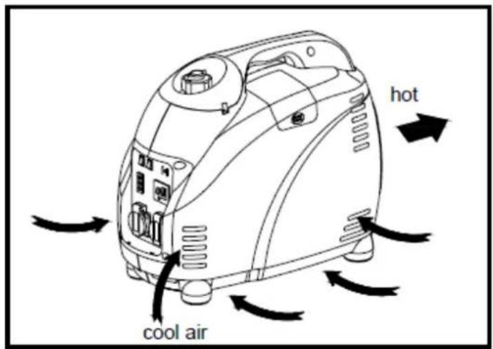
-
Protect children by keeping them at a safe distance from the power generator.
-
Do not install any extensions on the exhaust pipe.
-
Do not change the intake system.
-
Do not change the settings of the speed controller.
-
Do not remove the control panel and do not change the wiring.
Electrical safety
Danger of electric shocks!
The voltage that the generator generates is high enough to cause serious electric shocks or electrocution. Using a generator or electric device under damp conditions such as rain or snow, in the vicinity of a swimming pool or sprinkler systems and operation with wet hands could lead to electrocution. Keep the generator dry.
If the generator is stored outdoors, check the electrical components on the control panel before each use.
Moisture or ice can lead to a malfunction or short circuit in electrical components, resulting in electrocution.
In case of electric shock, call in medical assistance.
natural_image
Line drawing of a portable electricity cooker with attached circuit board and power cord (no text or symbols)-
Never touch the device with wet hands. This could cause an electric shock.
-
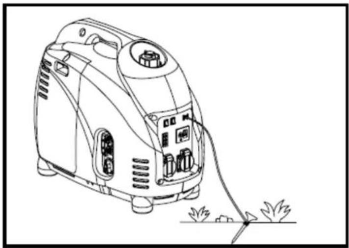
Ensure that you earth the generator.
Drive an earthing pin into the ground and connect it to the generator's earthing point ⏚Never use an earthing pin from other systems.
Caution: Use an earthing cable with adequate voltage capacity.
- Before use, the power generator and electrical equipment (including cables and plugs) must be examined to be sure they are not damaged and/or faulty.
- Do not connect the generator to the main power grid. The power generator may not be connected to another power source such as provided by the power company. In special cases where the objective is to create a standby connection with existing electrical systems, this may only be done by a qualified electrician who must weigh the difference between equipment that uses the public power grid and the generator.
- Do not connect the generator in parallel with another generator.
- The protection against electric shocks is based on the power circuit breakers that are specifically aligned with the power generator. If the circuit breakers must be replaced, they must be replaced with circuit breakers with identical values and characteristics.
- Because of high mechanical stresses, only tough, rubber insulated flexible cable (in accordance with IEC 60245-4) or a comparable cable must be used.
- The use of an extension cable is not recommended because it could cause overheating or fire. If the use of an extension cable cannot be avoided, ensure it is an undamaged, approved extension cable with earthing. When using extension leads/cable reels or mobile distribution networks, the resistance value may not be higher than 1.5 ohms.
As a reference, the total length of any extension leads/cable reels with a diameter of 1.5 mm^2 may not be longer than 60 metres. Extension leads/cable reels with a diameter of 2.5 mm^2 may not be longer than 100 metres.
Fire hazard
-
Do not use the generator in fire hazard situations. Some materials could catch fire because of the heat of the exhaust.
-
While in use, position the generator at least one metre away from buildings and other devices.
- Do not enclose the generator in any way.
- Keep flammable materials away from the generator.
- Some components of the combustion engine are hot and could cause buns. Pay attention to the warnings on the generator.
- The exhaust can be very hot and remain hot for some time even after switching the engine off. Do not touch the exhaust if it is hot. Allow the engine to cool down before putting the generator away.
-
If there is a fire, never pour water directly on the generator. Use a fire extinguisher specifically intended for electrical or oil fires.
-
Fill the tank carefully. Petrol is very flammable and fuel vapours can explode. First allow the engine to cool down after use. Fill the tank in a well-ventilated area and with the engine switched off. Do not fill the tank while it is in operation. Do not overfill the fuel tank. Never smoke in the vicinity of petrol and keep flames and sparks at a distance. Always store petrol in an approved tank. Before starting, remove any spilled petrol.
Description
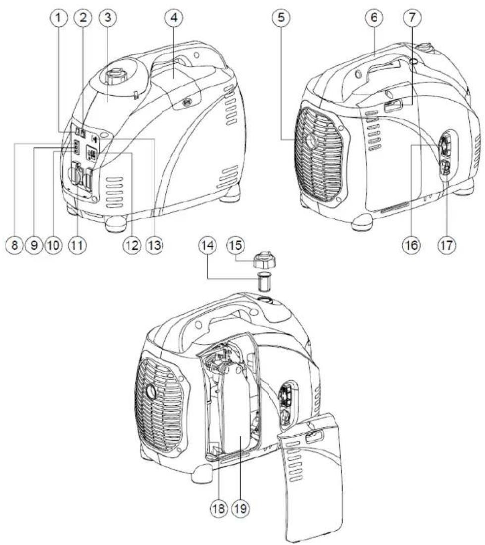
- Economy switch (ECON)
- Engine switch (ENG.SW)
- Fuel tank
- Spark plug cover
- Exhaust
- Carrying handle
- Choke lever
- Indicator light AC 230 V (OUTPUT)
- Overload light (OVERLOAD)
- Oil alert light (OIL ALERT)
- Power point AC230V\~ 2x
-
Power point DC 12V+
-
Earthing point ⏚
- Feul filter
- Tank cap
- Recoil starter
- Fuel cock
- Oil filler cap
- Air filter
1 - Oil safety system
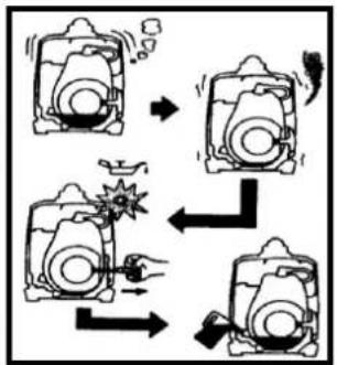
If the oil level falls below the lowest level, the engine will stop automatically. You must add oil and restart the engine.
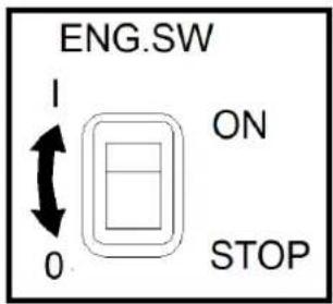
2 - Engine switch (ENG.SW)
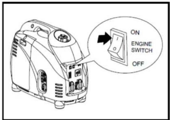
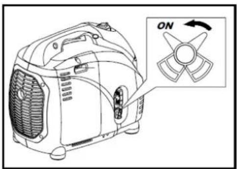
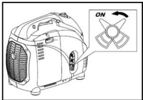
The engine switch switches the ignition system "ON" – the ignition system is switched on, the engine can be started.
"STOP" (OFF) – the ignition system is switched off. The engine will not operate/it will stop.
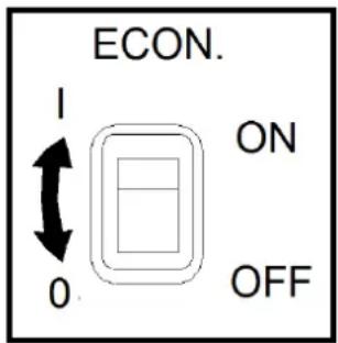
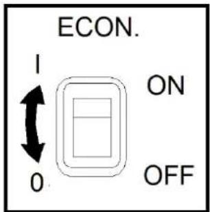
3 - Economy switch
If the Economy button is set to "ON", the engine speed will be adjusted to the connected load. The result is less noise and consumption.
flowchart
graph TD
    A["Step 1: Initial state"] --> B["Step 2: Collision"]
    B --> C["Step 3: Collision with explosion"]
    C --> D["Step 4: Final state"]
4 - The DC protection
The DC DC protector (the red button next to the DC socket) switches off the power consumption when the load exceeds the maximum values.
Beware! Reduce the connected load to within the specified maximum values if the protection switches off the motor.
5 - Venting button on tank cap
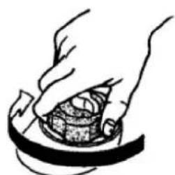
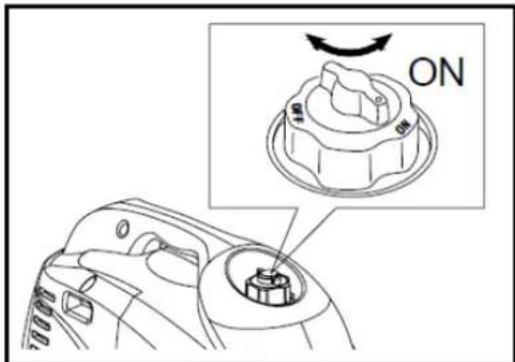
The tank cap is equipped with a venting button. Before starting the engine, the venting button must be turned clockwise from the closed position to the OPEN position.
This prevents the fuel tank from creating a
vacuum, which would prevent the fuel from running through properly. As soon as the engine is switched off, close the venting button by turning it counterclockwise. During transport and storage, the venting button must always be shut completely.
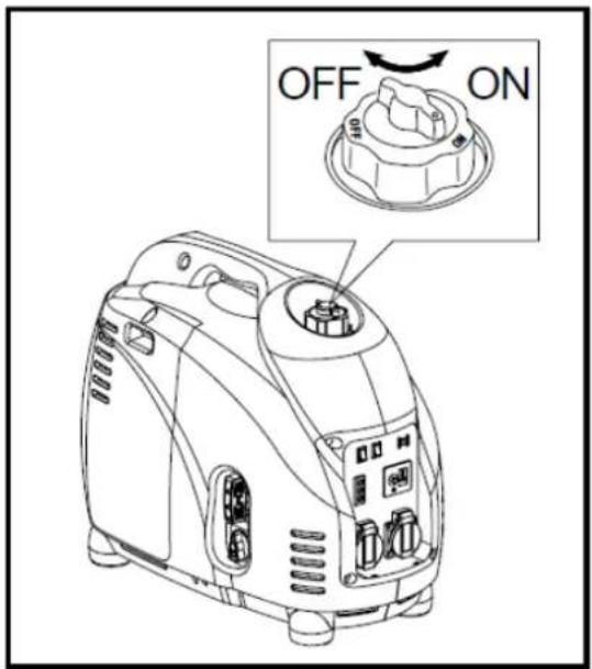
6 - Fuel cock
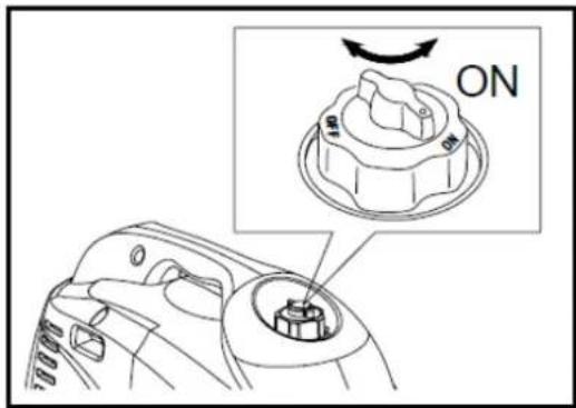
If you open the fuel cock (ON), the fuel supply
to the carburettor is opened. By closing this fuel cock (OFF), the supply is cut off.

natural_image
Line drawing of a portable air conditioner unit with no visible text or symbolsCheck before using
Caution:
- When using the generator for the first time, you must fill the tank with at least 2 liters of fuel.
- Before use, slowly pull the starter 20x all the way out to pump the gasoline into the carburetor.
• The usage check must be performed every time you use the generator
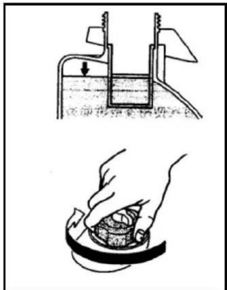
1 - Check the fuel level
- Ensure there is sufficient fuel in the tank.
- If there is too little, add unleaded petrol; ensure that the filter is always in the filling opening of the tank. See the figure.
• The fuel tank capacity is 5.7 liter.
Warning:
- Do not add fuel to an engine that is operating or hot!
- Close the fuel cock before you add fuel!
- Dust, dirt, water or other materials/objects may not contaminate the fuel.
- Do not fill the tank beyond the filter; if the fuel temperature increases later, it could expand.
- Close the tank cap carefully after filling!
- Remove any spilled fuel carefully before starting the engine.
- Keep the generator and the fuel away from naked flames!
natural_image
Two-step diagram showing a piston-cranked liquid level and a hand holding a container (no text or symbols)2 - Check the oil level
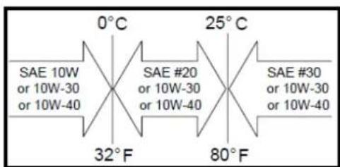
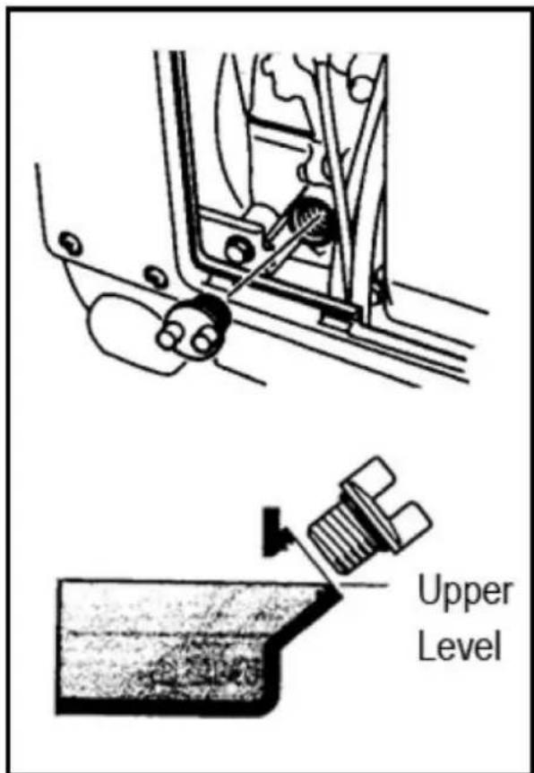
Ensure that the oil is at the maximum level in the oil tank. If necessary, add oil.
- Remove the side cover.
- Remove the cap with the dipstick and check the oil level.
- If the oil level is under the minimum level, oil must be added to the maximum level. Do not tighten the cap when you check the oil level.
- Change the oil if it is dirty.
• The oil tank capacity is 0,9 liter
• Recommended oil: SAE10W30/40
3 - Earthing
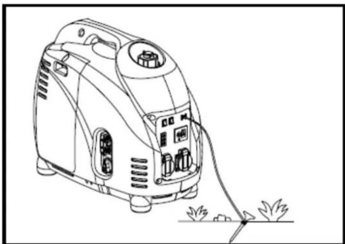
Equip the generator with an earthing that is properly connected and operates correctly. Drive an earthing pin into the ground and connect it to the generator's earthing point ⏚ Never use an earthing pin from other systems. Caution: Use an earthing cable with adequate voltage capacity.
natural_image
Line drawing of a portable electricity cooker with attached circuit board and power cord (no text or symbols)Operation
Caution:
- The generator is delivered without oil. If you do not fill the oil tank, the generator will not start.
- Ensure that the generator is perfectly level when you add oil. Tilting it can lead to overfilling and damage to the engine.
- Only use the generator on a paved, dust-free, sand-free surface.
1 - Start the engine
Caution:
a) Before starting the engine, do not connect any electrical equipment.
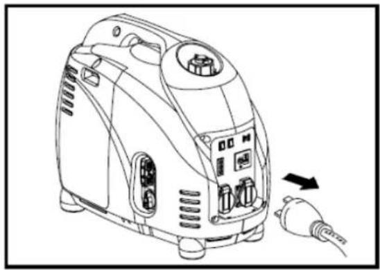
natural_image
Line drawing of a portable air purifier with attached plug (no text or symbols)b) Switch the Economy button to the "OFF" position (0).

c) Open the venting button on the tank cap.
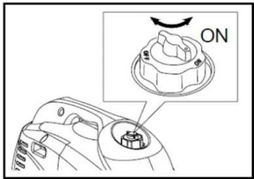
d) Open the fuel cock.
natural_image
Line drawing of a portable air conditioner unit with a highlighted ON/OFF button (no text or symbols on the device itself)e) Put the engine switch in the "ON" position.
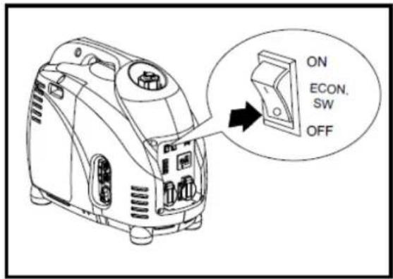
f) Put the choke lever in the position (CHOKE). This is not necessary if the engine is still warm.
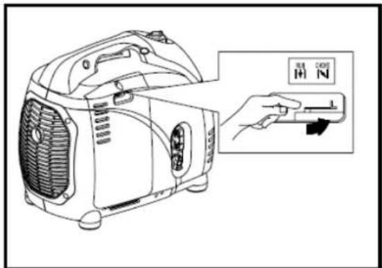
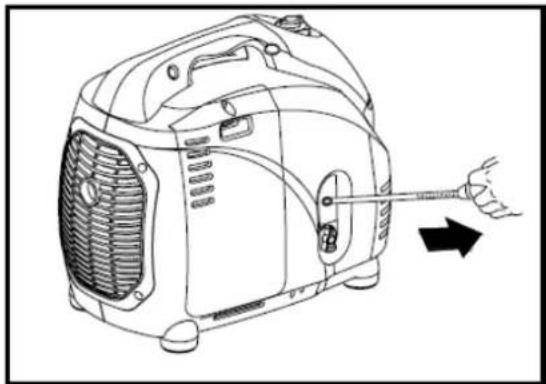
g) Pull the pull cord slowly until you feel resistance. This is the "compression point". Allow the lever to return to the starting position and now pull quickly. While doing so, hold the generator firmly in position using the lever to prevent it from falling over while pulling the pull cord. Do not pull the cord out entirely. After starting, allow the pull cord to
natural_image
Line drawing of a portable air conditioner unit with a hand holding a screwdriver, showing internal components and airflow direction (no text or symbols)return to its starting position while holding the lever. Repeat as necessary if the engine does not start with the first pull.
Caution: The pull cord may be pulled back very quickly and with force before you have released it. This may pull your hand with force in the direction of the generator, possibly injuring your hand.
Do not allow the lever to snap back. Ensure the lever rolls up slowly.
h) Allow the engine to warm up.
i) Return the choke lever to the operating position |↑| (RUN).
j) Give the generator a few minutes to warm up properly without a load.
2 - Connect electrical equipment
A - AC 230 V alternating current application
k) Check whether the AC indicator light shows that the voltage is correct (output light is green).
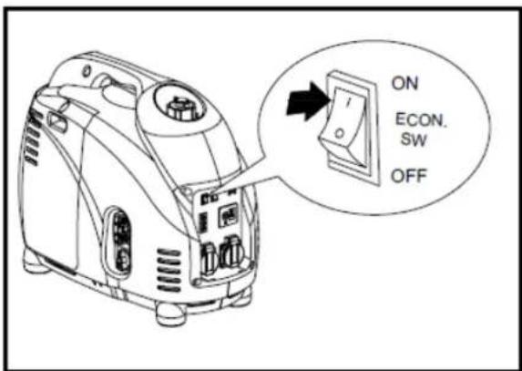
I) Put the Economy switch in the "ON" position.
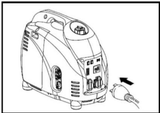
m) Ensure that all equipment to be connected is switched off.
n) Put the plug(s) of the equipment in the power point of the generator.
Warning:
- Ensure that the equipment to be connected is switched off.
- Ensure that the total connected capacity does not exceed the maximum.
- Ensure that the demanded and delivered voltages are the same.
- The Economy switch must be switched off if you use electrical equipment that requires a high peak current such as a compressor, high-pressure cleaner or a submersible pump.
natural_image
Line drawing of a portable air purifier with control panel and plug, no text or symbols presentB - Overload warning light
The overload warning light will turn red if an overload of connected equipment is detected, the generator overheats or if the output voltage increases. The voltage on the power point will switch off to protect the generator and connected equipment.
The green AC alternating current indicator light will switch off and the red overload warning light will switch on. After a few seconds, the engine will stop as well.
If the overload warning light switches on (and the engine has already stopped), take the following steps:
f) Switch all connected equipment off.
g) Switch the engine off if that has not already happened automatically.
h) Reduce the total connected power of connected equipment to within the maximum value of the generator.
i) Check if the vents are closed; remove the dirt or other obstructions.
i) After you have checked everything, restart the engine.
Warning:
- The AC 230 V power delivery is automatically reset if the engine is stopped and restarted.
- The overload warning light may turn on for a few second if electrical equipment is put into operation that requires a high peak current when starting. This is not a malfunction.
C - DC 12 V Direct current application
Caution: Exclusively for charging 12 V batteries!
Instructions for charging an accumulator:
a) Put the Economy switch to the "OFF" position.
b) Prepare the accumulator for charging:
c) Disconnect the accumulator terminals.
d) Remove all caps from the fluid filling opening.
e) Add distilled water to the maximum level (if required).
f) Measure the specific weight of the accumulator fluid using an acetometer and calculate the loading time according to the table on the right.
g) The specific weight for fully charging the accumulator should be 1.26 to 1.28. It is recommended that this be checked every hour.
h) Using the accumulator cables, connect the poles of the accumulator to the equivalent poles of the DC
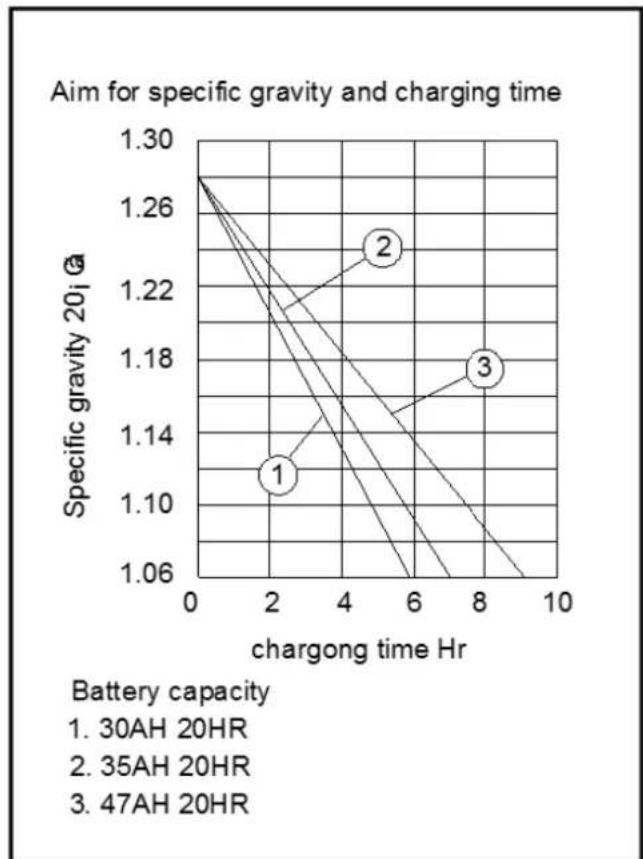
line
| Battery capacity | Specific gravity 20i @ | | ---------------- | ---------------------- | | 1 | 1.13 | | 2 | 1.23 | | 3 | 1.18 |direct current power point of the generator: + on + and - on - !
i) Check that all cables have been connected correctly and press the DC direct current protection to the "ON" position.
3 - Stopping the engine
e) Switch all connected equipment off and remove the plug(s) from the power point on the generator.
f) Put the engine switch to the "STOP" position.
g) Close the fuel cock, putting it in the "OFF" position.
h) Turn the venting button on the tank cap to the closed position (counterclockwise).
Special conditions
The maximum capacity of the generator is calculated under normal operating conditions. If the generator is used under special conditions, for example:
- Use at a great height;
- Use under extreme temperatures; or
- Use in extremely wet conditions.
The maximum capacity of the generator will be reduced. Contact your supplier for additional information.
Regular maintenance
1 - Maintenance chart
Regular maintenance is the most important condition for proper and safe operation.
| Component | Action | Before each use | Every month or 20 hours | Every 3 months or 50 hours | Every 6 months or 100 hours | Every 12 months or 300 hours |
| Spark plug | Check its condition, possibly adjust the opening and, if necessary, replace. | ● | ||||
| Engine oil | Check the oil level. | ● | ||||
| Change the oil. | ● | |||||
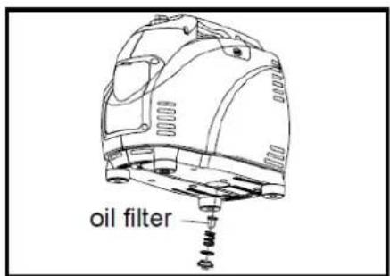
| Oil filter | Clean the oil filter. | ● | ||||
| Air filter | Clean the air filter and, if necessary, replace it. | ● | ||||
| Fuel filter | Clean the fuel filter and, if necessary, replace it. | ● | ||||
| Choke | Check the operation. | ● | ||||
| Play in the valve | Check and, if necessary, adjust when the engine is cold. | ● | ||||
| Fuel line | Check for kinks or damage and, if necessary, replace. | ● | ||||
| Exhaust system | Check for leaks. Seal correctly or replace the gasket. | ● | ||||
| Check the exhaust shield and, if necessary, clean or replace. | ● | |||||
| Carburettor | Check the choke operation. | ● | ||||
| Cooling system | Check the fan for damage. | ● | ||||
| Starting system | Check the operation of recoil starter. | ● | ||||
| Stationary rpm | Check and, if necessary, adjust. | ● | ||||
| Couplings and connections | Check and, if necessary, adjust. | ● | ||||
| Crankcase venting | Check the venting hose for kinks or damage and, if necessary, replace. | ● | ||||
| Generator | Check the indicator lights. | ● |
2 - Changing the engine oil
a) Put the device on a flat, horizontal surface and allow the engine to warm up for a few minutes. Switch the engine off and close the fuel cock (OFF). Turn the venting button on the tank cap closed by turning it counterclockwise.
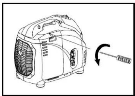
b) Unscrew the 4 screws and remove the side panel (see the figure).
c) Remove the oil fill cap.
d) Position a receptacle under the generator and tilt it so that all of the oil drains out.
e) Return the generator to its flat, horizontal surface.
f) Pour new engine oil in the tank up to the maximum level.
g) Screw the oil fill cap back in the opening.
h) Replace the cover and retighten the 4 screws.
- Recommended engine oil: SAE 10W30/40.
Warning:
- Ensure that no foreign material gets into the crankcase.
- Do not add oil to a generator that is not in a horizontal position; this could cause overfilling and damage to the engine.
natural_image
Line drawing of a portable air conditioner unit with a screwdriver inserted, showing no text or symbols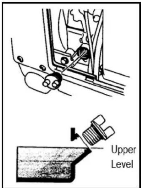
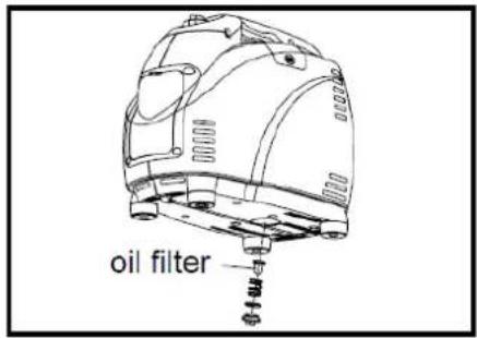
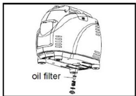
- Change the oil filter every 100 operating hours.
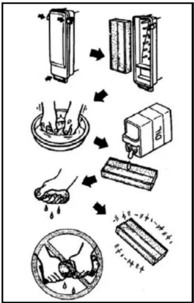
3 - Air filter
It is very important that the air filter be kept in good condition. Contamination due to a poorly installed, incorrectly maintained or wrong air filter causes damage and premature wear and tear to the engine. Always keep the filter clean.
a) Unscrew the 4 screws and remove the side panel (see the figure for changing the oil).
b) Remove the cover of the air filter and the filter.
c) Wash the filter using mild soap and allow it to dry thoroughly.
d) Drip some oil on the filter and squeeze the filter together so that the oil spreads and excess oil drains (squeeze it, do not wring it!). The filter must be damp but not dripping.
e) Replace the filter in its proper position.
f) Replace the cover and refasten the side panel.
Warning: Never operate the generator without an air filter! This could lead to extreme wear and tear of the engine.
flowchart
graph TD
    A["Water receiving"] --> B["Receiving container"]
    B --> C["Water washing bowl"]
    C --> D["Water bath"]
    D --> E["Water drop"]
    E --> F["Water cleaning plate with liquid"]
    F --> G["Water disinfection with solid material"]
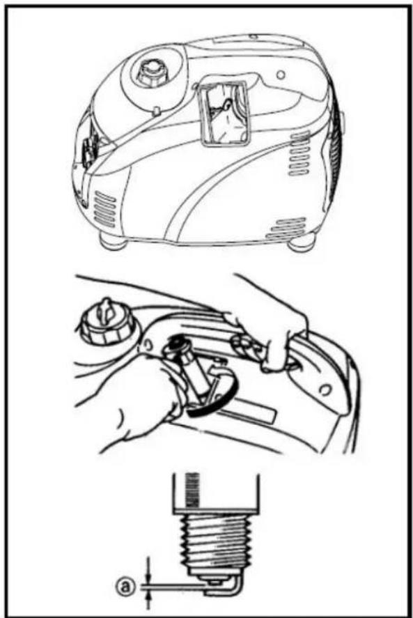
4 - Cleaning and adjusting the spark plug
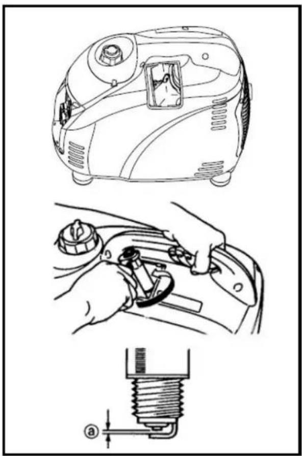
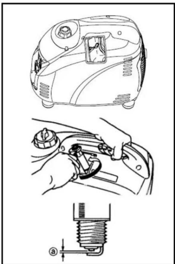
a) Unscrew the screw and remove the upper panel.
b) Remove the spark plug cap and unscrew the spark plug.
c) Remove any deposit there, check for discolouration (standard colour is brown) and the distance between the poles. This should be between 0.6 and 0.7 ~mm . If necessary, adjust somewhat. If the spark plug appears to be worn, replace it with the same type: See the Technical data table.
d) Screw the spark plug back in the opening and replace the spark plug cap on the spark plug.
e) Replace the upper panel.
natural_image
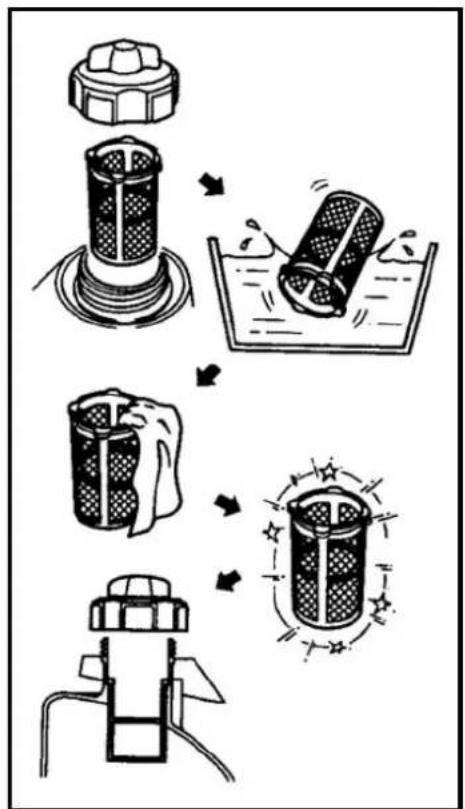
Technical line drawings of a vacuum cleaner and its internal components, showing assembly and mounting (no text or symbols)5 - Filter fuel tank
a) Remove the tank cap and the filter
b) Wash the filter in a solvent; if it is damaged, it must be replaced.
c) Rub the filter dry and replace it.
Warning: Ensure you close the fuel cap.
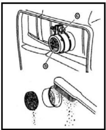
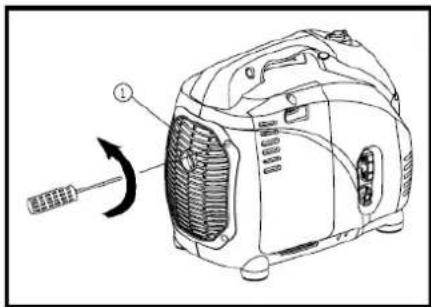
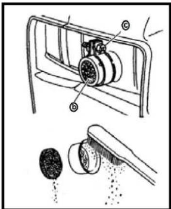
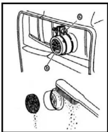
6 - Spark arrester
Warning:
- During and immediately after operation, the engine and exhaust are very hot! Do not touch them with your bare skin exposed or with clothing. Allow the device to cool down before performing inspections or repairs!
f) Remove the rear panel by unscrewing the four screws.
g) Loosen the clamp using a screwdriver.
h) Pull the spark arrester from the exhaust (if necessary, use the flat head of a screwdriver to dislodge it carefully).
i) Remove the carbon build-up from the spark arrester using a brush.
j) Replace the spark arrester and the rear panel in their proper places.
natural_image
Line drawing of a portable air conditioner unit with a screwdriver and fan blade (no text or symbols)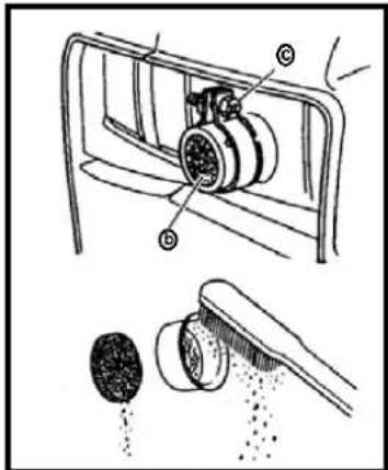
Troubleshooting
1 - The engine will not start
- No fuel is being sent to the carburettor.
- There is no fuel in the tank - add fuel.
- There is fuel in the tank – turn the fuel cock and the venting button to the "ON" position.
- The fuel line is blocked - clean it.
- The carburettor is blocked – clean it.
• The engine does not have sufficient oil.
- Add oil.
- Problems with the ignition system: not enough sparks.
- The spark plug is dirty or wet – clean and/or dry it.
- A problem with the ignition system – consult your dealer.
2 - The generator is not providing any electricity
- The AC safety facility is set to "OFF".
- Stop the engine and restart it.
• The DC safety facility is set to "OFF".
- Press to reset it.
Storage
When storing for a longer period of time, a generator requires a few preventative procedures to prevent deterioration.
1 - Drain the fuel
a) Remove the tank cap and allow all of the fuel to drain from the tank.
b) Remove the side panel and allow the fuel to drain from the carburettor as well.
2 - Engine
a) Remove the spark plug and pour a teaspoon of engine oil (SAE 10W30 or 20W40) in the opening. Put the spark plug back in its proper position.
b) Turn the engine a couple of time by pulling gently on the recoil starter (without sparks).
c) Pull the recoil starter until you feel resistance.
d) Stop pulling now.
e) Clean the exterior of the generator.
f) Store the generator in a dry, well-ventilated area and cover it.
g) The generator must remain upright.
Disposing of the device
natural_image
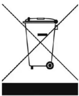
Simple line drawing of a trash bin with diagonal lines crossing it, no text or symbols present.Within the EU, this symbol means that this product may not be discarded with normal household waste. Discarded devices contain valuable materials that can and must be recycled in order not to cause negatively affect the environment or our health due to unregulated waste collection. For this reason, bring a discarded device to a collection point designated for this purpose or go to the company where you bought the device. They can ensure that as many components of the device as possible are recycled.
Wiring diagram
See pages 90.
CE declaration
The undersigned declares the following:
Eurom, Kokosstraat 20, 8281 JC Genemuiden, The Netherlands
that the product:
petrol generator (four-stroke)
registered under the brand:
EUROM
Types:
INDEPEND 2500, INDEPEND 3100
comply with the requirements of Machinery Directive 2006/42/EC, EMC Directive 2014/30/EU and the following standards:
EN ISO 8528-13:2016
EN 55012:2007+A1:2009
EN 61000-6-1:2007
W.J. Bakker, Managing Director
Dank
natural_image
Line drawing of a portable vacuum cleaner with attached circuit board and power cord (no text or symbols)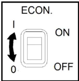
natural_image
Line drawing of a portable air conditioner unit with ON/OFF toggle switches (no text or symbols on the device itself)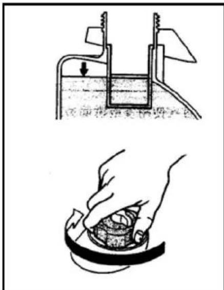
kontrolliere n.
natural_image
Line drawing of a portable air purifier with attached circuit board and power cord (no text or symbols)Funktionsweise
Achtung!
natural_image
Line drawing of a portable air purifier with attached plug, showing internal components and a directional arrow (no text or symbols)natural_image
Line drawing of a portable air conditioner unit with a highlighted ON/OFF button (no text or symbols on the device itself)natural_image
Line drawing of a portable air conditioner unit with a hand pulling the cable (no text or symbols)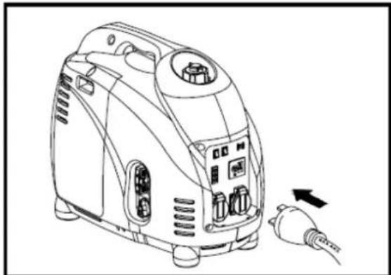
natural_image
Line drawing of a portable air purifier with attached plug, showing internal components and wiring (no text or symbols)Warnung:
natural_image
Line drawing of a portable air conditioner unit with a screwdriver inserted, showing airflow direction (no text or symbols)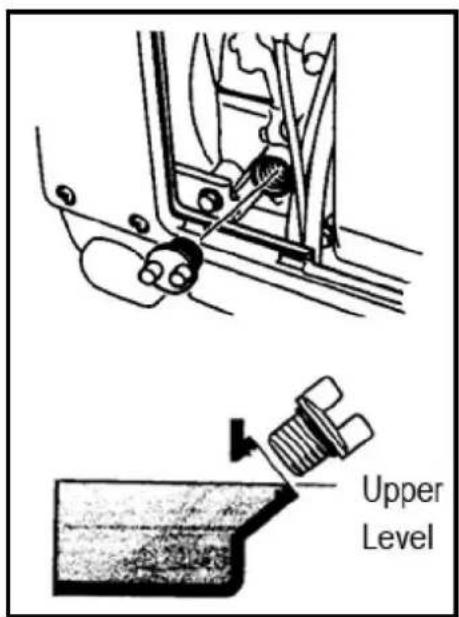
3 - Luftfilter
flowchart
graph TD
    A["Water washing"] --> B["Water washing with water"]
    B --> C["Water washing with water bath"]
    C --> D["Water washing with water drop"]
    D --> E["Water washing with water clean"]
    E --> F["Water washing with water clean"]
    F --> G["Water washing with water clean"]
    G --> H["Water washing with water clean"]
    H --> I["Water washing with water clean"]
    I --> J["Water washing with water clean"]
natural_image
Technical line drawings of a vacuum cleaner and its internal components, showing assembly and mounting (no text or symbols)6 - Funkenschirm
Warnung:
Problembeseitigung
natural_image
Simple line drawing of a trash bin with two crossed lines indicating no waste or prohibition (no text or symbols)Merci
natural_image
Line drawing of a portable electricity cooker with attached circuit board and power cord (no text or symbols)flowchart
graph TD
    A["Step 1: Initial state with noise"] --> B["Step 2: Formation of explosion"]
    B --> C["Step 3: Formation of explosion"]
    C --> D["Step 4: Final state with impact"]
4 - La protection DC
3 - Prise de terre
natural_image
Line drawing of a portable electricity cooker with attached circuit board and power cord (no text or symbols)Fonctionnement
Attention :
natural_image
Line drawing of a portable air purifier device with attached plug (no text or symbols)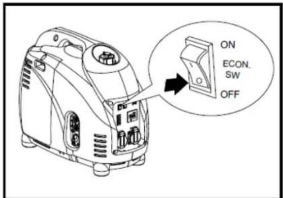
natural_image
Line drawing of a portable air conditioner unit with a highlighted ON/OFF button (no text or symbols on the device itself)natural_image
Line drawing of a portable air conditioner unit with a hand pulling the cable (no text or symbols)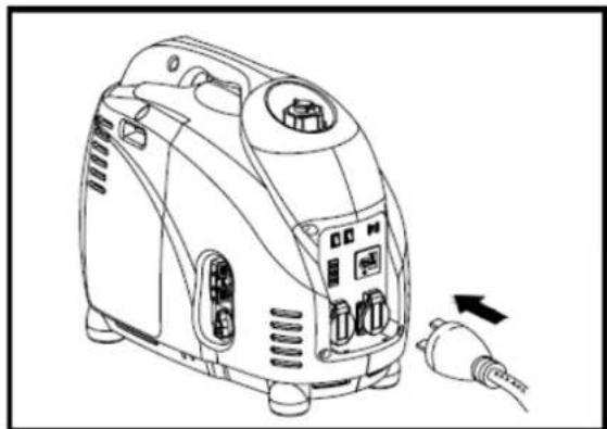
natural_image
Line drawing of a portable air purifier with attached plug, showing internal components and a directional arrow (no text or symbols)Avertissement :
line
| Battery capacity | Specific gravity 20i @ | | ---------------- | ---------------------- | | 1.30AH | 1.26 | | 2.35AH | 1.22 | | 3.47AH | 1.18 |natural_image
Line drawing of a portable air conditioner unit with a screwdriver inserted, showing no text or symbols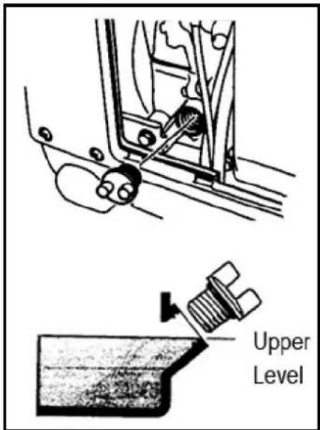
Avertissement :
3 - Filtre à air
flowchart
graph TD
    A["Water Pump"] --> B["Receiving Tank"]
    B --> C["Water Seal"]
    C --> D["Water Toward Down"]
    D --> E["Hand Stipa Down"]
    E --> F["Toile Down"]
    F --> G["Toile Stamped Down"]
    G --> H["Toile Stamped Up"]
    H --> I["Toile Stamped Up with Discharge"]
natural_image
Technical line drawings of a vacuum cleaner and its internal components, including tool manipulation and mechanical assembly (no text or symbols)6 - Pare-étincelles
Avertissement :
natural_image
Simple line drawing of a trash bin with no text or symbols
- INDEPEND 2500 - 3100
- Dank
- Brandgevaar
- - Motorschakelaar (ENG.SW)
- Waarschuwing:
- - Aarding
- Werking
- Let op:
- - Luchtfilter
- - Filter brandstoftank
- - vonkenvanger
- Problemen oplossen
- Symbols used
- Technical data
- Safety information
- IMPORTANT SAFETY REGULATIONS
- User responsibility
- Important safety warnings
- Electrical safety
- Danger of electric shocks!
- Fire hazard
- Description
- - Oil safety system
- - Engine switch (ENG.SW)
- - Economy switch
- - The DC protection
- - Venting button on tank cap
- - Fuel cock
- Check before using
- Caution:
- - Check the fuel level
- Warning:
- - Check the oil level
- - Earthing
- Operation
- - Start the engine
- - Connect electrical equipment
- B - Overload warning light
- C - DC 12 V Direct current application
- Instructions for charging an accumulator:
- - Stopping the engine
- Special conditions
- Regular maintenance
- - Maintenance chart
- - Changing the engine oil
- - Air filter
- - Spark arrester
- Troubleshooting
- - The engine will not start
- - The generator is not providing any electricity
- Storage
- - Drain the fuel
- - Engine
- Disposing of the device
- Wiring diagram
- CE declaration
- EUROM
- Funktionsweise
- Achtung!
- Warnung:
- - Luftfilter
- - Funkenschirm
- Problembeseitigung
- Merci
- - La protection DC
- - Prise de terre
- Fonctionnement
- Attention :
- Avertissement :
- - Filtre à air
- - Pare-étincelles
Brand : Eurom
Model : Independ 3100
Category : Generator