ALP 200 (2006) - Motorcycle Beta - Free user manual and instructions
Find the device manual for free ALP 200 (2006) Beta in PDF.



User questions about ALP 200 (2006) Beta
0 question about this device. Answer the ones you know or ask your own.
Ask a new question about this device
Download the instructions for your Motorcycle in PDF format for free! Find your manual ALP 200 (2006) - Beta and take your electronic device back in hand. On this page are published all the documents necessary for the use of your device. ALP 200 (2006) by Beta.
USER MANUAL ALP 200 (2006) Beta
natural_image
Close-up of a mechanical component with visible wiring and a labeled section (A), no readable text or symbols present.natural_image
Close-up of mechanical components with no visible text or symbolsIDENTIFICAZIONE MOTORE ALP 200
natural_image
Close-up of a mechanical component with labeled parts (B), no readable text or symbols present.FORNITURA
natural_image
Line drawing of a mechanical tool setup with a cylindrical rod, two rectangular components, and a screwdriver (no text or symbols)I
CARICO
Tipo: Trial competition TT
| PNEUMATICO | ANT. | POST. |
| Dimensioni | 2,75 - 21" | 4,00 - 18" |
| Pressione bar | 0,8 | 0,6 |
| Pressione a pieno carico bar | 1,3 | 1,3 |
text_image
Labeled diagram of a motorcycle with numbered parts for identification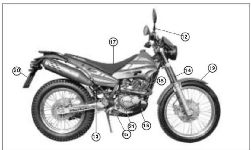
text_image
Labeled diagram of a motorcycle with numbered parts for identificationtext_image
Labeled diagram of a motorcycle body with numbered parts for identification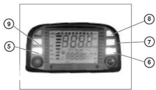
text_image
⑨ ⑤ 8:00:00 7 6text_image
SPEED MAX 88:88 rpm Mph TRP Km/h AVS LAP 88:88:88 AM PM min 000 CLK WStext_image
LAP 0 00:00:00 Km/hORE:MINUTI:SECONDI 00:00:00,
text_image
00:00 Km/h LAP 0 00MINUTI:SECONDI 00:00,
text_image
TRP 0 Km/h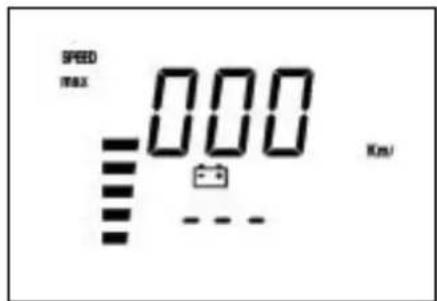
text_image
SPEED max 000 Km/Jtext_image
LAP 0 Km/htipo ....Michelin - Trial Competition TT
pressione bar .... ant. 0,8/post. 0,6
pressione bar a pieno carico .... ant. 1,3/post. 1,3
dimensioni ....ant. 2,75 - 21"/post. 4,00 - 18"
tipo ...... PIRELLI Scorpion
pressione bar .... ant. 1,6/post. 1,8
pressione bar a pieno carico .... ant. 2,0/post. 2,4
dimensioni ......ant. 90/90 - 21"/post. 120/80 - 18"
CAPACITÀ DI RIEMPIMENTO
candela NGK R CR7 HSA
text_image
Labeled mechanical assembly diagram showing components A, B, C, D, and E with visible wiring and componentsBOBINA A.T.
natural_image
Close-up of a car's head and side panel showing mechanical components (no visible text or symbols)FUSIBILE - INTERMITTENZA - RELE CA- VALLETTO
natural_image
Close-up of a car engine bay with labeled component 'A' and 'ALP200' (no other text or symbols visible)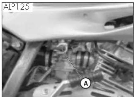
text_image
ALP125 A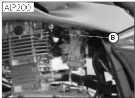
text_image
ALP200 B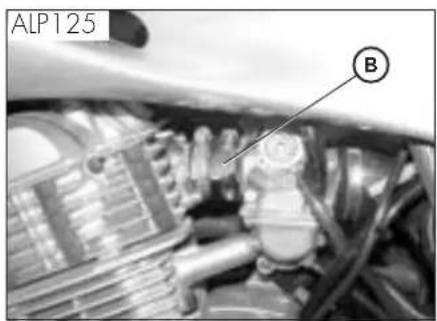
text_image
ALP125 BAvvertenza:
natural_image
Mechanical component diagram showing a housing with labeled part A (no text or symbols beyond label)text_image
Labeled diagram of a spacecraft or spacecraft interior with marked points E, C, and D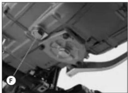
natural_image
Close-up of a mechanical assembly with visible components and a labeled point F (no text or symbols beyond label)natural_image
Close-up of a mechanical engine component with labeled part 'A' (no other text or symbols visible)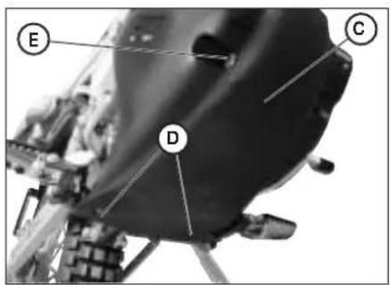
text_image
Labeled diagram of a spacecraft or spacecraft interior with marked points E, C, and D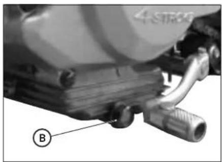
natural_image
Close-up of a mechanical component with labeled parts (B) and no visible text or symbols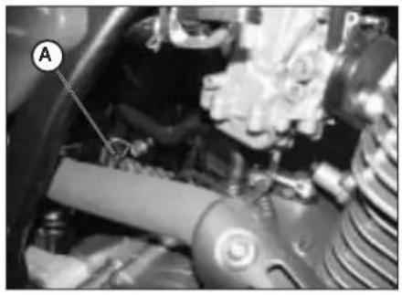
natural_image
Close-up of a mechanical engine component with labeled parts (A), no visible text or symbols beyond the label.TUBO RACCOLTA FUMI
text_image
Labeled mechanical component diagram showing a lever and keyway with annotations A, B, and COLIO POMPA FRENI, SPURGO FRENI
Freno anteriore
natural_image
Close-up of a bicycle wheel assembly with labeled parts A and B (no text or symbols beyond labels)Spurgo freno posteriore
text_image
Close-up of bicycle wheel components with labeled parts D and C, likely for safety or maintenance reference.I
text_image
B AOLIO FORCELLE
Steli
natural_image
Close-up of a motorcycle seat with a circular mark labeled 'D' pointing to the side (no other text or symbols visible)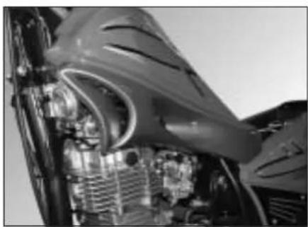
natural_image
Close-up of an aircraft engine bay with visible internal components and structural details (no text or symbols)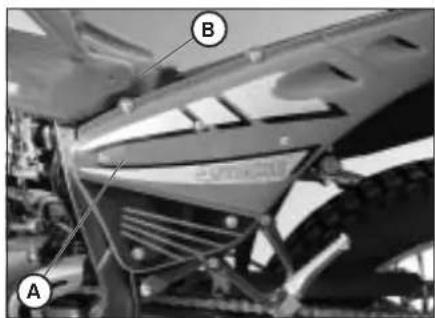
text_image
A B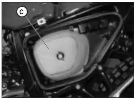
natural_image
Close-up of a mechanical component with a labeled point C, showing internal structure and no readable text or symbols.FILTRO ARIA
natural_image
Close-up of industrial machinery components with no visible text or symbols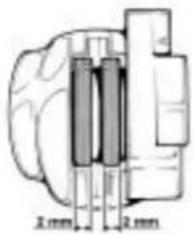
text_image
2mm 2mmFRENO ANTERIORE
Controllo
natural_image
Close-up of industrial machinery components (no visible text or symbols)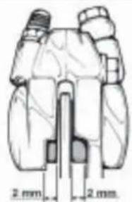
natural_image
Technical line drawing of a mechanical component with two 2 mm dimensions labeled (no text or symbols beyond dimension markers)FRENO POSTERIORE
Controllo
text_image
Anatomical diagram of a mechanical or biological structure with labeled parts C and C1, likely from an engineering or medical illustration.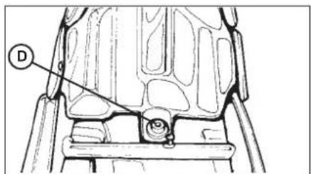
text_image
Technical diagram of a mechanical component with labeled part D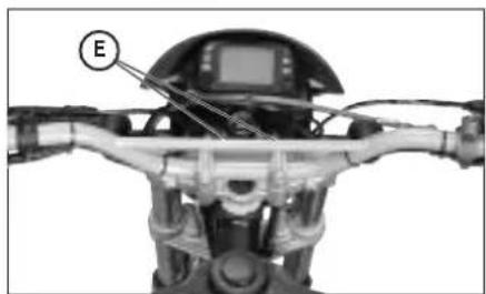
natural_image
Mechanical robot assembly with labeled component E, no visible text or symbols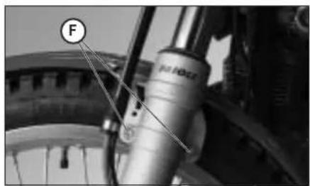
natural_image
Close-up of a bicycle wheel assembly with labeled component 'F' (no text or symbols beyond label)natural_image
Technical line drawing of a mechanical linkage assembly (no text or symbols)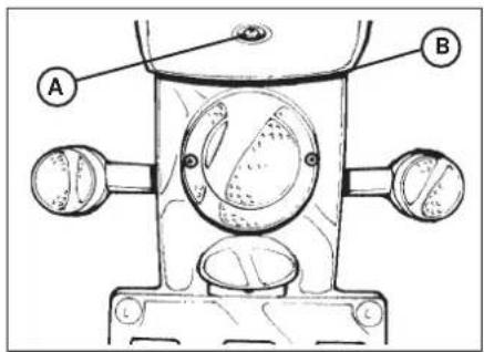
text_image
A B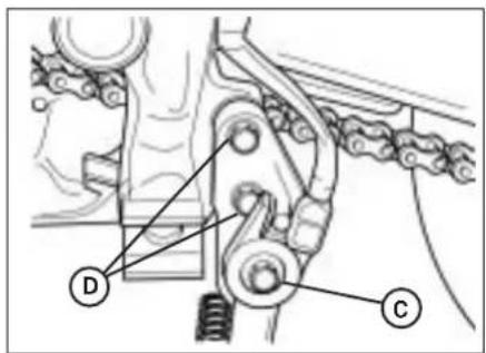
text_image
Technical diagram of a mechanical linkage system with labeled components D and C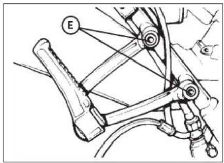
text_image
E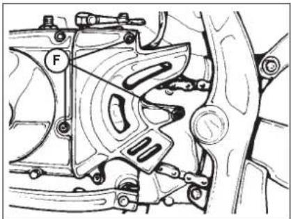
natural_image
Mechanical assembly diagram showing a motor or gear mechanism with no visible text or symbolsnatural_image
Close-up of a mechanical assembly with labeled component A (no readable text or symbols)natural_image
Close-up of a mechanical brake lever assembly with hoses and calipers (no visible text or symbols)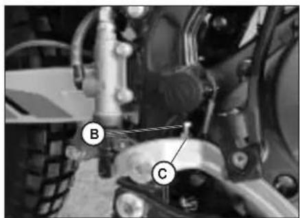
text_image
B C
text_image
D F EREGOLAZIONE FRENI
Freno anteriore
natural_image
Side view of a motorcycle's wheel and side-mounted blade (no text or symbols visible)
natural_image
Close-up of hands adjusting a mechanical component (no visible text or symbols)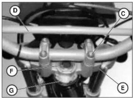
text_image
Labeled mechanical assembly diagram showing components D, C, F, G, and E with numbered parts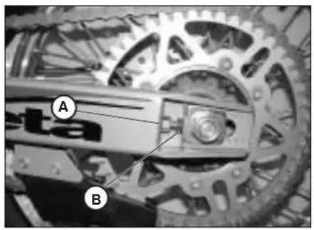
text_image
A B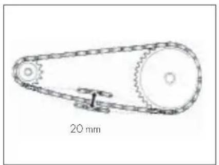
natural_image
Technical line drawing of a mechanical pulley system with 20 mm scale indicator (no text or symbols on the diagram itself)natural_image
Close-up of mechanical components with no visible text or symbols
natural_image
Close-up of a mechanical assembly with labeled components (no readable text or symbols)SOSTITUZIONE PASTIGLIE FRENI FRENO ANTERIORE
natural_image
Close-up of a bicycle wheel and brake system with visible components (no text or symbols)natural_image
Close-up of a car's wheel assembly and engine components (no visible text or symbols)CONTROLLO USURA
natural_image
Close-up of hands operating a mechanical device with wires and components (no visible text or symbols)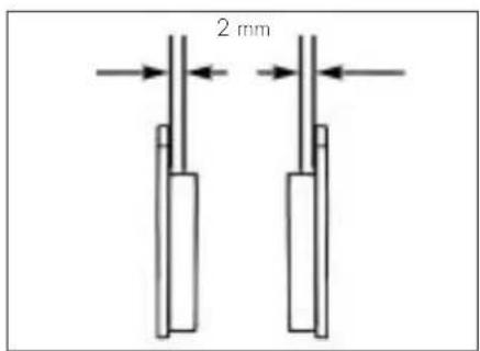
text_image
2 mmSOSTITUZIONE LAMPADA DEL FARO ANTERIORE
natural_image
Technical line drawing of a mechanical device with circular components and bolts (no text or symbols)SOSTITUZIONE LAMPADA DEL FARO POSTERIORE
natural_image
Technical line drawing of a mechanical component with circular features and two side ports (no text or symbols)
text_image
Anatural_image
Empty dotted line pattern on white background, no text or symbols presentALP4T 125/200 cc
Thanks for you preference, and have a good time! This handbook contains the information you need to properly operate and maintain your motorcycle.
The data and specifications provided in this manual does not constitute an engagement on the part of BETAMOTOR S.p.A. BETAMOTOR reserves the right to make any changes and improvements to its models at any moment and without notice.
IMPORTANT
We recommend checking all the tightenings after the first one or two hours' ride over rough ground. Special attention should be paid to the following parts:
- rear sprocket
- footrest supports
- front brake caliper
- mudguard bracket
- engine bolts
- shock absorber bolts
- wheel spokes
- rear frame
IMPORTANT
For any servicing requirements, please contact Betamotor's authorized service network.
Operating notes.... 85
Ecologic guide 85
Riding safety 86
CHAPTER 1 GENERAL INFORMATION 87
Vehicle identification data 88
Delivery 88
Load 89
Tyres 89
Familiarizing with your vehicle 91
Keys and locks 92
Ignition switch / Steering lock 92
Helmet lock....92
Instrument panel and controls....93
Speedometer setting and operating instructions.... 94
General specifications 111
Engine specifications ALP125.... 113
Engine specifications ALP200....114
Wiring diagrams ALP125.... 115
Wiring diagrams ALP 200....116
Electrical devices 119
Checks and maintenance before and after off-road use 122
Recommended lubricants and fluids 123
Running-in 123
Starting the engine 124
Shutting off the engine 125
Refuelling.... 126
CHAPTER 3 CHECKS AND MAINTENANCE.... 127
Engine oil and oil filter ALP 200....128
Engine oil and oil filter ALP 125....130
Fume collecting tube 131
Brake pump oil - Bleeding the brakes 131
Fork oil.... 133
Air filter 134
Spark plug 135
Brakes 136
Battery 137
Removing the bodywork 138
Notes for trial use.... 139
Cleaning and checking the vehicle 141
Scheduled maintenance 142
Prolonged inactivity 143
CHAPTER 4 ADJUSTMENTS.... 145
Adjusting the brakes 146
Adjusting the clutch.... 146
Adjusting the slow running 147
Fuel flow adjustment (ALP125 only).... 147
Adjusting the throttle play 147
Checking and adjusting the steering play 147
Tensioning the chain 148
Adjusting the headlight 149
CHAPTER 5 REPLACEMENTS 151
Replacing the brake pads 152
Replacing the headlight bulb 154
Replacing the rear light bulb.... 154
Replacing the turn indicator bulbs 155
CHAPTER 6 TROUBLESHOOTING .... 157
INDEX 159
OPERATING NOTES
- The vehicle must be accompanied by: number-plate, registration document, tax disc and insurance.
- Do not carry any animals or objects which are not securely fastened to the vehicle, or exceed the vehicle's overall dimensions or the maximum load specified by the manufacturer.
•Riding without a helmet is forbidden. - Any modifications of the engine or other parts resulting in a power and/or speed increase are punishable by severe sanctions including the confiscation of the vehicle.
- To protect your safety and that of others, always wear a helmet and adopt a safe riding conduct.
WARNING
Any modifications and tampering with the vehicle during the warranty period exempt the manufacturer from all responsibility and make the warranty null and void.
ECOLOGIC GUIDE
- Every vehicle powered by an internal combustion engine produces an amount of noise (noise pollution) and gases (air pollution) which varies with the riding style.
- The abatement of noise and air pollution levels is the duty of everybody. Avoid full-throttle starts, sudden acceleration and abrupt braking. This will reduce noise emission as well as the wear and tear of the tyres and mechanical parts, and will also allow a considerable reduction in fuel consumption.
RIDING SAFETY
- Observe the Highway Code.
•Always put on and fasten a homologated helmet.
•Always keep the helmet visor clean. - Avoid wearing garments with hanging ends.
- Do not keep sharp or brittle objects in your pockets while riding.
- Be sure to correctly adjust the rearview mirrors.
- Always ride in a seated position, with both hands on the handlebars and both feet on the footrests.
•Always pay attention and do not allow anything to distract you while riding. - Do not eat, drink, smoke, use a mobile phone, etc. while riding.
- Do not wear headphones to listen to music while riding.
- Never ride abreast with other vehicles.
- Do not tow and avoid being towed by other vehicles.
•Always keep a safe distance from other vehicles. - Ride with the lights (low beam) on, even during the day.
- Do not sit on the vehicle when it is on its stand.
- Do not start off while the vehicle is on its stand.
- Do not pull out the stand when the vehicle is facing downhill.
- Avoid swaying and wheelies as they are extremely dangerous for your own and other people's safety as well as for your vehicle.
- Always apply both brakes on dry roads with no gravel and sand. Using one brake may result in dangerous and uncontrolled skidding.
• To reduce the braking distance, always apply both brakes. - On wet roads, ride at moderate speed and be very careful, especially when applying the brakes.
- Do not start the engine in closed places.
CONTENTS
CHAPTER 1 GENERAL INFORMATION
Vehicle identification data
Delivery
Load
Tyres
Familiarizing with your vehicle
Keys and locks
Ignition switch / Steering lock
Helmet lock
Instrument panel and controls
Specifications
Wiring diagram
Electrical devices
1
GENERAL INFORMATION
FRAME IDENTIFICATION
natural_image
Close-up of mechanical components with visible wiring and a labeled section (A), no readable text or symbols present.VEHICLE IDENTIFICATION DATA
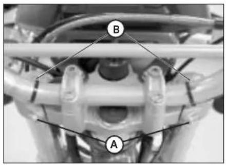
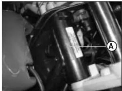
Frame identification data A are stamped on the right side of the steering head tube.
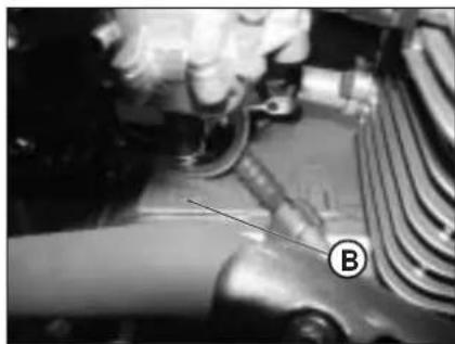
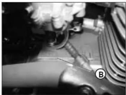
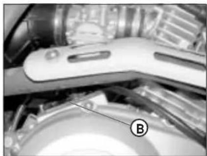
Engine identification data B are stamped in the area shown in the figure.
WARNING
Tampering with the identification numbers is severely punished by law.
ENGINE IDENTIFICATION ALP 200
natural_image
Close-up of mechanical components with a labeled arrow pointing to a component (no readable text or symbols)ENGINE IDENTIFICATION ALP 125
natural_image
Close-up of a mechanical device with labeled component B (no readable text or symbols)DELIVERY
- The vehicle is supplied ready for use. However, it is advisable to conduct a few simple checks before riding:
- Check the tyre pressures (when first refuelling).
- Check the oil level in the engine.
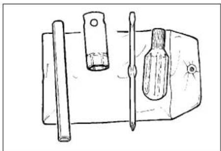
•The following items are supplied as standard and are contained in a plastic envelope placed in a compartment under the saddle: operation and maintenance manual, tool kit (ignition spanner, double-function screwdriver).
natural_image
Line drawing of a mechanical device with three components: a cylindrical rod, a rectangular tool, and a flat screwdriver (no text or symbols)GB
LOAD
•Maximum load (rider + passenger): 280 kg.
• To avoid making the vehicle unstable, do not carry bulky or heavy objects.
- Do not carry objects that stick from the vehicle or cover the lighting and signalling devices.
•The helmet must be put in its compartment with the top facing downwards.
TYRES
WARNING
For your riding safety, frequently check the lyres.
- Keep the tyre pressures within the prescribed range.
- Check the tyre pressures every other week.
•Always measure the inflating pressures when the tyres are cold.
TYRES
Make: MICHELIN
Type: Trial competition TT
| TYRE | FRONT | REAR |
| Size | 2.75 - 21" | 4.00 - 18" |
| Pressure bar | 0.8 | 0.6 |
| Full-load pressure bar | 1.3 | 1.3 |
The vehicle is also homologated with all-terrain tyres:
Make: PIRELLI
Type: Scorpion
| TYRE | FRONT | REAR |
| Size | 90/90 - 21" | 120/80 - 18" |
| Pressure bar | 1.6 | 1.8 |
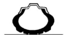
pressure is too low
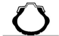
pressure is correct
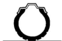
pressure is too high
1
Note:
The tyre (TUBE TYPE) tread depth must never be less than 2 mm.
Failure to comply with this rule is punished under the regulations in force.
- Before riding, check the tyres for cuts, cracks, abrasions, bulges, etc. If any defects are found, have the tyres checked by an expert as riding with a damaged tyre can be extremely dangerous.
- If a tyre gets punctured, stop the vehicle immediately. Riding with a flat tyre is dangerous and may seriously damage the tyre itself and the wheel rim.
*Higher inflating pressures are recommended when riding in maximum load condition (refer to the table on page 89).
FAMILIARIZING WITH THE VEHICLE
text_image
Labeled diagram of a motorcycle with numbered parts for identification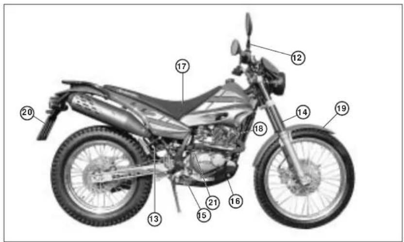
text_image
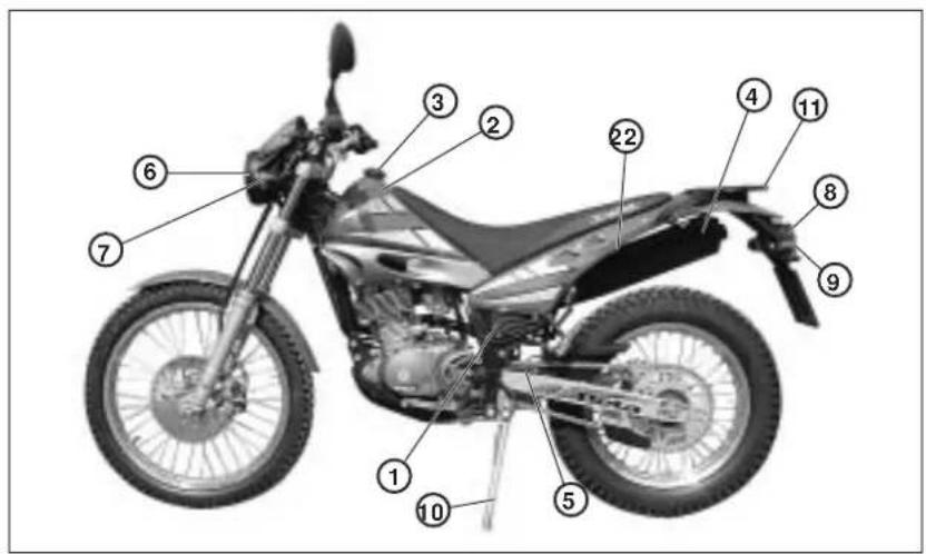
Labeled diagram of a motorcycle with numbered parts for identificationMain parts:
1 - Air filter
2- Fuel tank
3- Tank cap
4- Silencer
5- Rear shock
absorber
6- Headlight
7- Front turn indicators
8- Rear light
9- Rear turn indicators
10- Side stand
11 - Carrier
12- Rearview mirrors
13- Passenger's footrests
14- Fork
15- Rider's footrests
16- Undercowl
17- Saddle
18-Engine
19- Front mudguard
20- Number-plate holder
21- Kick-start
22- Helmet lock
1
KEYS AND LOCKS
The vehicle is supplied with two keys and the related spares for the ignition switch/steering lock and the helmet lock.
WARNING
Do not keep the spare keys in the vehicle. Keep the keys in a safe and easy-to-reach place. The code number stamped on the keys should be copied on this manual (or elsewhere) so it can be used to ask for duplicates should both keys be lost.
IGNITION SWITCH/STEERING LOCK
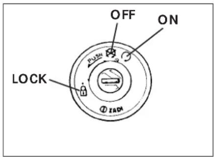
It controls the ignition circuit and the steering lock, and the opens the saddle.
OFF: Electrical equipment disabled.
ON: The vehicle can be started.
LOCK: Steering lock on.
To lock the handlebar, turn it to the left, press the key, rotate it anticlockwise all the way and then release it.
text_image
OFF ON LOCK ZADHELMET LOCK
Insert the smaller key into the lock located on the left side under the saddle, and then rotate it anticlockwise to open the helmet hook.
GB
INSTRUMENT PANEL AND CONTROLS
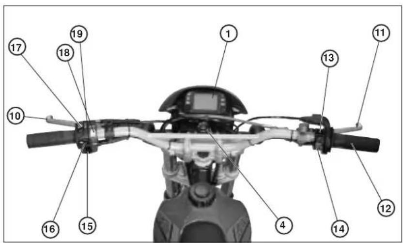
text_image
Labeled diagram of a motorcycle body with numbered parts for identification
text_image
Labeled diagram of a digital display device with numbered parts pointing to function buttons1-LCD
4- gnition switch
5- Neutral warning light
6- Turn indicator warning light
7- High beam warning light
8- Reserve fuel warning light
9- Stand warning light
10- Clutch lever
11-Front brake lever
12- Throttle twist grip
13-Engine start button
14- Engine stop button
15-Turn indicator switch
16- Horn button
17-Lights switch
18-Lights selector switch
19- Passing
Note: The lighting of the stand warning light indicates that the stand is down. For safety reasons, the engine stops as soon as the gears are engaged.
1
SPEEDOMETER SETTING AND OPERATING INSTRUCTIONS
(for manufacturer and dealers)
A description of the basic procedure for setting up the digital instrument is provided for information purposes only. We recommend having the operation performed by an authorized Betamotor dealer.
ALP 125 - ALP 200 Series
CONTENTS
PARAGRAPH SUBJECT
10.1 Wheel specifications
10.2 Engine specifications
10.3 Preloaded codes
10.4 Loaded codes
20.0 LEVEL 1 SETUP (for manufacturer and dealers)
20.1 Performing level 1 setup
20.2 Selecting codes
20.3 Checking codes
20.4 Entering uncoded values
20.4.1 Setting Ln (wheel circumference) or di (wheel diameter)
20.4.2 Setting the number of pulses per wheel revolution
20.4.3 Setting the number of pulses per engine revolution
20.4.3.1 Setting the number of pulses for the maximum rpm
20.4.4 Selecting Km/h or Mph
20.4.5 Setting the number of hours to the next oil change
20.4.6 Setting the number of hours or kilometres to the next service
20.5 Exiting setup
40.0 LCD DISPLAY
40.1 Operation and display of pages and icons
40.2 Blanking out pages
40.3 Resetting the TRP, SPEED max and LAP parameters.
50.0 Monitoring icons (engine oil and service icons)
50.1 Checking the active contents of the monitoring icons.
GB
10.1 Wheel specifications (factory loaded)
Size of the wheel fitting the revolution sensor. Enter the wheel diameter or circumference in mm (maximum allowable values 9999; if, for example, the wheel diameter is 695 mm, after the measurement has been entered the display should read 0695) and the number of pulses per revolution (maximum allowable value 99). Once the value has been entered, if the number of pulses is less than 10, e.g. 1, the display should read 01.
NB: The SCROLL button can be operated in one of two ways:
Short operation (button pressed for ≤ 1 second): displays the next page.
Long operation (button pressed for ≥ 5 seconds): selects the currently displayed function, allowing its values to be checked, entered, altered and, in some cases, stored.
For the sake of convenience, reference will only be made to the SCROLL button on the handlebars, but the same results can be obtained by using the MODE button on the speedometer (the MODE button can only be operated while the vehicle is stationary).
10.2 Engine specifications (only if tachometer is active)
Number of pulses per revolution and maximum nominal number of revolutions required to adjust the bar. Any parameters entered while the sensor is not present will not alter operation but will bring up the page on the LCD display with the parameters and the bar set to zero. The sensor input is on connector pin 12. The number of pulses per engine revolution uses the same criteria as the number of pulses per wheel revolution, whereas the number of engine revolutions only requires the thousands and hundreds to be specified. For example, to enter 15,000 revolutions, enter 150 on the large digits; to enter 8,500 revolutions, enter 085 on the large digits.
10.3 Preloaded codes (factory loaded)
Four factory-defined codes contain the wheel parameters as well as monitoring parameters such as 'hours to oil change' and 'hours or km to service'. Only the monitoring parameters can be altered at all times. Identification is obtained by highlighting a code number on the LCD display. The first code to be entered will be 0001.
The preloaded codes can only be altered by the manufacturer. It should be noted that, if the instrument is reprogrammed, the total number of kilometres covered is set to zero.
10.4 Loaded codes
Each speedometer layout contains a table showing the codes and the related descriptions. The contents of each code can be checked at any moment.
20.0 LEVEL 1 SETUP
It allows choices to be made and values to be entered in all fields:
- Code selection
or, alternatively:
- setting of
- wheel circumference or diameter,
• number of pulses per wheel revolution,
• number of pulses per engine revolution, - maximum rpm.
- entering or altering the
- hours to oil change,
• km or hours to service,
• speed unit, Km/h or Mph, the default being Km/h.
20.1 Performing level 1 setup
- With the instrument switched off, press and hold down the SCROLL button.
- Start the vehicle while the battery is connected.
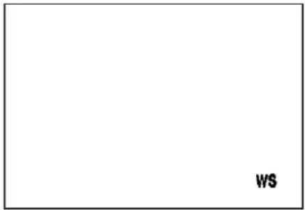
- After approximately 7 seconds W S will be displayed in the bottom right corner as shown in Figure 1.
- Hold down the SCROLL button and operate the high beam button, turning the beam on and off 5 times.
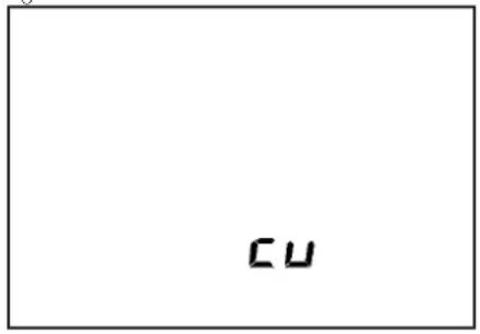
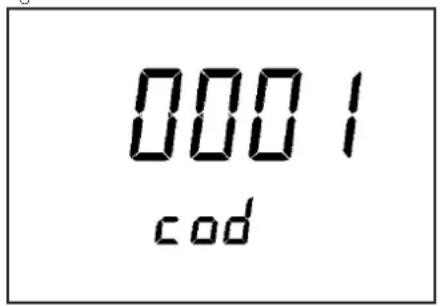
- When SCROLL is released, the display will appear cu as shown in Figure 2 if the instrument has never been set up before. Otherwise the code adopted during the previous setup will be displayed as shown in Figure 3.
Figure 1
text_image
WSFigure 2
text_image
cu20.2 Selecting codes
- Pressing SCROLL for a short time cycles through the other codes until the display appears as shown in Figure 2.
Table of codes
| Model | Alp 4.0 | Alp 200 cc | |
| Motard M4 | |||
| Code | 0001 | 0002 | 0003 |
| Wheel circ. | 2105 | 2115 | 1830 |
Figure 3
text_image
0001 cod• After selecting the desired code, press and hold down SCROLL until WS is displayed in the bottom right corner (Figure 4). Once the button is released, the code is activated and the display appears as shown in Figure 5.
- If the configuration is complete, there are two possibilities:
- exiting the setup procedure and launching the test as described in paragraph 40.0 by turning the speedometer off and then on again;
- checking the code as described in paragraph 20.3.
- If no code is appropriate, repeat the procedure until the display is as shown in Figure 2, which can be obtained by briefly pressing SCROLL while Figure 3 is displayed. Subsequently press SCROLL until WS is shown and then release it to activate the procedure described in paragraph 20.4.
Figure 4
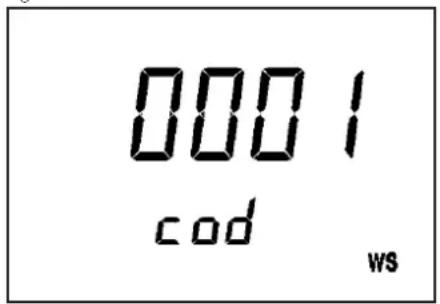
text_image
0001 cod ws20.3 Checking codes
The codes can be checked at all times. Perform the setup procedures again by following the steps described in paragraph 20.1. Once the code has been selected and stored, the display will appear as shown in Figure 5.
Press SCROLL until the horizontal bars shown in Figure 7 are displayed. Releasing the button will display the wheel circumference corresponding to the selected code (unmodifiable).
Briefly pressing the SCROLL button brings up Figure 6.
Press SCROLL until the horizontal bars shown in Figure 7 are displayed. Releasing the button will display the wheel diameter corresponding to the selected code (unmodifiable).
Briefly pressing the SCROLL button brings up Figure 8.
Press SCROLL until the horizontal bars shown in Figure 7 are displayed. Releasing the button will display the number of pulses per wheel revolution corresponding to the selected code (unmodifiable).
Briefly pressing the SCROLL button brings up Figure 9.
Press SCROLL until the horizontal bars are displayed. Releasing the button will display the number of pulses per engine revolution corresponding to the selected code (unmodifiable).
Briefly pressing the SCROLL button brings up Figure 10.
Press SCROLL until the horizontal bars are displayed. Releasing the button will display the number of engine revolutions corresponding to the selected code (unmodifiable).
Pressing SCROLL again will successively display figures 11, 12 and 13 which, even though linked with the codes, can always be altered as described in paragraph 20.4. At the end of the procedure, End appears on the display.
Pressing SCROLL for a short time while End is displayed returns to the menu, going back to Figure 5.
Pressing SCROLL until the bars - - - - are displayed and then releasing it causes the instrument to go into test mode as described in paragraph 40.0. The same result is obtained by turning the instrument off and then on again.
20.4 Entering uncoded values
20.4.1 Setting Ln (wheel circumference) or di (wheel diameter)
Ln (wheel circumference in mm): pressing SCROLL for a short time changes to di (wheel diameter in mm); pressing SCROLL again changes back to Ln and so forth. To be able to proceed, at least one of the two values must be other than 0.
Figure 5
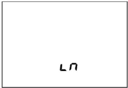
text_image
L0Figure 6
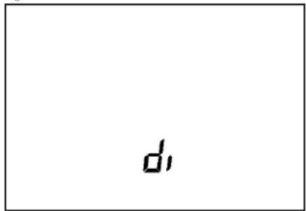
text_image
d,Figure 7
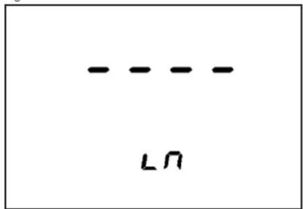
text_image
--- --- LΩFigure 8
text_image
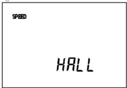
SPEED HALLAfter performing the procedure described in paragraphs 20.1 and 20.2 and with the display appearing as shown in Figure 5 or 6, press and hold down the SCROLL button until the display is as shown in Figure 7.
When SCROLL is released, the bars will be replaced by 0000, or by the previously entered value with the leftmost digit blinking. Pressing SCROLL for a short time increases the value by one unit. Leaving SCROLL inactive for 2 seconds will cause the blinking of the second digit from the left. Use the same procedure for the second and all the other digits.
Once Ln has been entered, wait 2 seconds until the value disappears from the display. To alter the entered value, simply repeat the procedure. Briefly pressing the SCROLL button causes the display to appear as shown in Figure 6. Once Ln has been entered, the page will display the corresponding diameter, calculated automatically by the instrument. To change the value, follow the procedure described for Figure 7. Alternatively, wait until the value disappears from the display and briefly press SCROLL. The display will then appear as shown in Figure 8.
20.4.2 Setting the number of pulses per wheel revolution
HALL Speed (number of pulses per wheel revolution).
With the display appearing as shown in Figure 8, press and hold down the SCROLL button until the bars - - - - are displayed. When the button is released, either 00 or the previously loaded value is displayed. The value is updated and stored using the same procedure described for Figure 7.
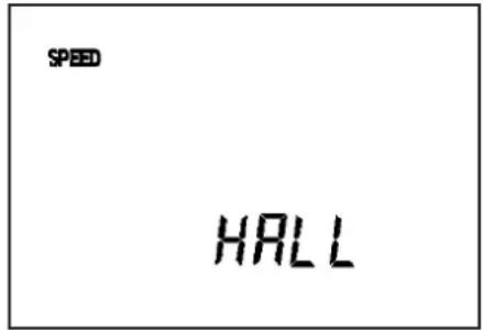
Pressing SCRÖLL for a short time causes the display to appear as shown in Figure 9.
20.4.3 Setting the number of pulses per engine revolution (only if requested)
The parameters can be entered manually by attaching a transducer to connector pin 12. If no tachometer is present, enter 00 on page 9 or page 10. This will prevent the tachometer page from being displayed.
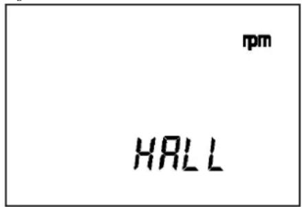
HALL rpm (number of pulses per engine revolution)
Press and hold down the SCROLL button until the bars - - - - are displayed. When the button is released, either 00 or the previously entered value is displayed. The value is updated and stored using the same procedure described for Figure 7. Pressing SCROLL for a short time brings up Figure 10.
20.4.3.1 Setting the number of pulses for the maximum rpm
The tachometer displays the number of revolutions through 5 small digits and the bar. To set the full-scale reading, it is first necessary to enter the maximum rpm.
max (number of pulses per engine revolution)
Press and hold down the SCROLL button until the bars - - - - are displayed. When the button is released, 000 will be displayed in large digits and 00 on small digits. The value is updated and stored using the same procedure described for Figure 7, bearing in mind that 100 stands for 10,000 rpm. Once the value has been stored, the display will appear as shown in Figure 10.
Pressing SCROLL for a short time brings up Figure 11.
Figure 9
text_image
SPEED HALLFigure 10
text_image
rpm HALLFigure 11
text_image
Mph Km/hFigure 12

text_image
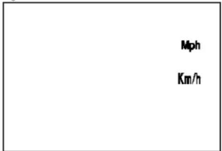
CLK20.4.4 Selecting Km/h or Mph
Press and hold down the SCROLL button until the bars - - - - are displayed.
As soon as the button is released, only Km/h or Mph will blink to denote which unit is active at that moment.
Briefly press SCROLL to toggle between units.
To confirm the current selection, press and hold down the SCROLL button until W S is displayed in the bottom right corner.
Once the button is released, the display will appear as shown in Figure 11.
Pressing SCROLL for a short time brings up Figure 12.
20.4.5 Setting the number of hours to the next oil change
Press and hold down the SCROLL button until the bars - - - - are displayed. The value is updated and stored using the same procedure described for Figure 7. Pressing SCROLL for a short time brings up Figure 13.
20.4.6 Setting the number of hours or kilometres to the next service
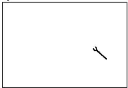
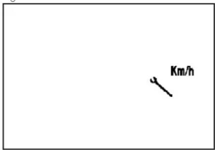
Press and hold down the SCROLL button until the bars - - - - are displayed. When the button is released, the display will appear as shown in Figure 14. Pressing SCROLL for a short time toggles between Km/h and CLK.
To confirm the current selection, press and hold down the SCROLL button until W S is briefly displayed in the bottom right corner. After releasing the button, enter and save the value by following the procedure described for Figure 7. At the end of the operation, the display will appear as shown in Figure 13. Pressing SCROLL for a short time brings up the End caption.
Figure 13
natural_image
Simple black wrench icon on white background (no text or symbols)Figure 14
text_image
Km/h20.5 Exiting setup
Pressing SCROLL for a short time while End is displayed returns to the menu, bringing back the display to the status shown in Figure 5.
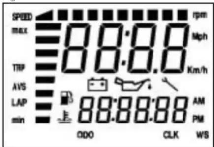
Pressing SCROLL until the bars - - - - are displayed and then releasing it causes the instrument to go into test mode (Figure 15).
The same result is obtained by turning the instrument off and then on again.
The test is a general check of all the segments and icons on the LCD display and of all the warning lights.
The test lasts 3 seconds.
At the end of the test the default page will be displayed.
Figure 15 - TEST
text_image
SPEED max 00:00 00:00 TIP AVS LAP min rpm Mph Km/h 88:88:88 AM PM ODO CLK WS40.0 LCD DISPLAY
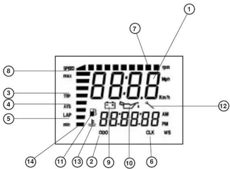
40.1 Operation and display of pages and icons
1 ISTANT SPEED
2 ODO - TOTAL COUNTER
3 TRP - TRIP COUNTEER
4 AVS-TRP AVERAGE SPEED
5 LAP - STOPWATCH (FORMATS HH:MM)
6 CLK - CLOCK FORMATS hh:mm:ss, con 12h e 24h, e mm:ss
7 TACHOMETER BARS
8 SPEED max - MAXIMUM SPEED
9 ICON BATTEERY
10 ICON HOURS TO OIL CHENGE
11 ICON FUEL
12 ICON SERVICESPANNER
13 ICON TEMPERATURE WATER
14 ALTERNATOR OUTPUT VOLTAGE BAR
text_image
1 7 8 SPED 00:00 rpm MAX 00:00 Mph TRP Km/h AXS LAP min 88:88:88 AM 000 PM CLK WS 12 5 14 11 13 2 9 10 61
Order of pages on LCD display
The different pages can only be viewed in succession starting from the default page.
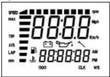
Page 1 - TEST
text_image
SPEED max 88:88 rpm Mph TRP Km/h AVS LAP 88:88:88 AM PM min 000 CLK WSTurn the ignition switch to the ON position. General check of all the icons and bars on the LCD display and warning light test.
The test lasts 3 seconds.
At the end of the test the default page is displayed.
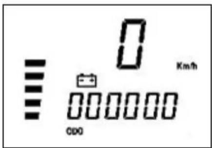
Page 2 - DEFAULT PAGE
text_image
0 Km/h 0000000 CDDThe default page is automatically displayed at the end of the test.
Displayed information:
Battery - Shows the battery charge on a vertical bar (min. 10.4 V, max. 14.5 V).
Instant speed at the top (max. 199 km/h or Mph).
ODO - Total counter measuring the kilometres or miles covered from the initial setup. It is displayed at the bottom (max. reading 999,999 kilometres or miles). The parameter cannot be reset
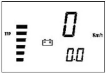
Page 3 - TRP
text_image
TDP 0 0.0 KeV/hWhile page 2 is displayed, briefly press MODE if the vehicle is stationary or SCROLL while travelling to bring up page 3.
The new page is displayed as soon as the button is released.
Displays:
Instant speed at the top (max. 199 km/h or Mph)
TRP Trip counter, displayed at the bottom (max. 999.9 km or miles)
The counter can be reset manually (see paragraph 40.3) or automatically when 999.9 km or miles are totalled.
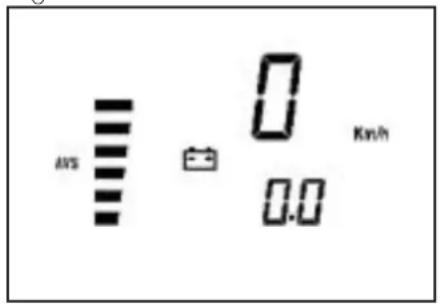
Page 4 - AVS
text_image
MVS 0 0.0 Km/hWhile page 3 is displayed, briefly press MODE if the vehicle is stationary or SCROLL while travelling to bring up page 4.
The new page is displayed as soon as the button is released.
Displayed information:
Instant speed at the top (max. 199 km/h or Mph)
AVS Actual average speed for TRP (calculated only while travelling) at the bottom.
The parameter cannot be reset manually. It is only reset at the same time as the TRP page.
Page 5 - LAP
-Stopwatch hours:minutes:seconds
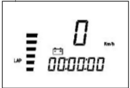
text_image
LAP 0 00:00:00 Km/hWhile page 4 is displayed, briefly press MODE if the vehicle is stationary or SCROLL while travelling to bring up page 5.
The new page is displayed as soon as the button is released.
Displayed information:
Instant speed at the top (max. 199 km/h or Mph). It displays:
HOURS:MINUTES:SECONDS 00:00:00 at the bottom.
Operation: The controls operate only when page 5 or 6 are displayed.
- Manual start/stop obtained by briefly pressing the SCROLL button.
-Automatic start/stop from wheel pulse. Three seconds after the wheel has come to a halt, the stopwatch ceases to operate and the delay is compensated for.
Page 6 - LAP
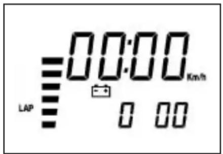
text_image
00:00 LAP 0 00 Km/hPage 7 - CLK
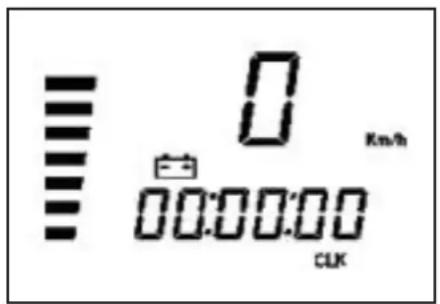
text_image
0 Km/h 00:00:00 CLKStopwatch minutes:seconds:tenths of a second
Pressing SCROLL for 1.5 seconds while page 5 is displayed brings up figure 21 for 1 second with the bars
- - : - - : - at the top.
Holding down SCROLL brings up page 5 again.
Releasing the SCROLL button brings up page 6.
Displayed information:
Stopwatch format
MINUTES:SECONDS 00:00
displayed at the top. Two small digits are used for tenths of a second. It works exactly as page 5, of which it represents an extension.
When this page is reset, page 5 is also reset and vice versa.
Instant speed on small digits (max. 199 km/h or Mph)
Clock hours:minutes:seconds
Releasing the SCROLL button brings up page 7. Displayed information:
Instant speed at the top (max. 199 km/h or Miph)
Clock HOURS:MINUTES:SECONDS at the bottom, 00:00:00.
The parameter can be adjusted by pressing MODE or SCROLL while the vehicle is stationary.
If Km/h has been selected, the clock will operate in 24-hour format. 23:59:59
If Miph has been selected, the clock will operate in 12-hour format. 11:59:59 with AM/
PM added automatically when Mph is selected.
Clock setting procedure
- Press the MODE or SCROLL button until the hour digits start blinking.
- Releasing the button and then pressing it again. Increases the hours by one unit. Holding down the button causes the figures to change rapidly. Leaving the button inactive skips to step 4.
- Release the button when the correct hour setting has been obtained.
- After 2 seconds the minute digits start blinking.
- Use the procedure described at step 2. Leaving the button inactive skips to step 8.
- Release the button when the correct minute setting has been obtained.
- After 2 seconds the second digits start blinking.
- Use the procedure described at step 2.
- Release the button when the correct second setting has been obtained. The new time setting is stored after 2 seconds.
- Changing the speed unit from Km/h to Mph causes the time display to change from the 24-hour to the 12-hour format.
Page 8 - CLK
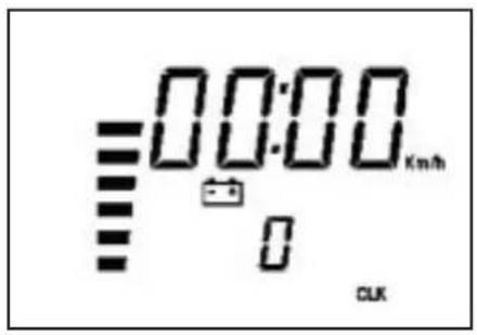
text_image
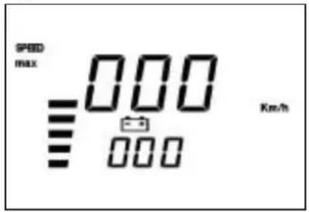
=00:00 km/h CLKPage 10 - SPEED max
text_image
SPEED MAX 000 3.5 000 Km/hClock minutes:seconds
While page 7 is displayed, briefly press
MODE if the vehicle is stationary or SCROLL while travelling to bring up page 8.
The new page is displayed as soon as the button is released.
Displayed information:
Clock format
MINUTES:SECONDS 00:00
at the top. The parameter can only be adjusted by pressing MODE or SCROLL while minutes or seconds are selected and the vehicle is stationary.
It also updates page 7, of which it represents an extension.
Instant speed at the top (max. 199 km/h or Mph).
While page 8 is displayed, briefly press
MODE if the vehicle is stationary or SCROLL while travelling to bring up page 9.
The new page is displayed as soon as the button is released.
Displayed information:
Instant speed at the top (max. 199 km/h or Mph)
SPEED max Maximum speed reached from the last time the parameter was reset. It can be reset manually.
40.2 Blanking out pages
If a page is of no interest to the user, it can be blanked out while remaining active to speed up the display of the next page.
All the pages can be blanked out, individually or in sets, with the exception of default page 2.
text_image
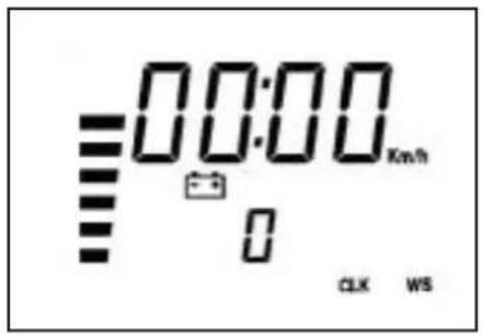
00:00 km/h 0 CLK WSTo blank out a page:
While the page is displayed, press MODE or SCROLL and hold it down until WS appears in the bottom right corner of the LCD display.
When the button is released, the page will no longer be visible.
To display all blanked out pages again:
While the default page is displayed, press
MODE or SCROLL and hold 'it down' until WS appears in the bottom right corner of the LCD display.
If no page had been previously blanked out, all pages will be blanked out.
To display the pages again, repeat the above procedure.
40.3 Resetting the TRP, SPEED max and LAP parameters.
The following parameters can be reset:
- TRP, trip counter, and consequently AVS.
- SPEED max, maximum speed reached by the vehicle.
Times indicated by LAP in both configurations' while either of the two pages is displayed. The parameters can be reset by pressing the MODE button while the vehicle is stationary or the SCROLL button at all time.
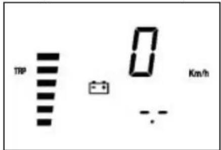
Resetting the TRP and SPEED max parameters
text_image
TRP 0 Km/h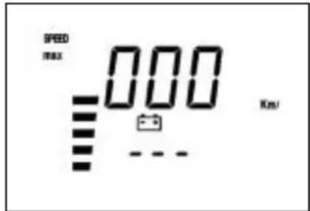
text_image
SPEED max 000 Km/sPress MODE or SCROLL for at least 5 seconds, causing 0.0 to be displayed in place of the figure.
The TRP parameter can only be reset while the vehicle is stationary. Resetting TRP also causes AVS to be reset.
Resetting the LAP parameter
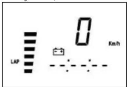
text_image
LAP 0 Km/hWhen the LAP time is reset, pages 5 and 6, which are strictly dependent on it, are also reset.
The figures will be replaced by the horizontal bars, which will remain visible for 1 second.
Releasing the MODE or SCROLL button while the bars are displayed resets the figure.
Holding down the MODE or SCROLL button brings up the next page while retaining the figures on the current page.
50.0 MONITORING ICONS (engine oil and service icons)
OIL ICON
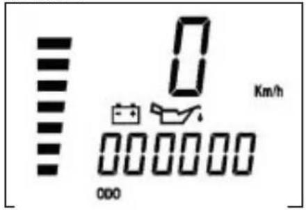
text_image
0 Km/h 000When 90 per cent of the hours making up the oil change interval have elapsed, the oil icon appears steadily on all pages. As soon as the preset value is reached, the icon starts to blink. Contact an authorized Betamotor dealer.
SERVICE ICON
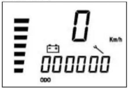
text_image
0 Km/h ODOWhen 90 per cent of the hours or kilometres making up the preset service interval have been totalled, the service icon is displayed steadily on all pages. As soon as the preset value is reached, the icon starts to blink. Contact an authorized Betamotor dealer. Regarding the planned maintenance to be performed after the first 1000 kilometres, please refer to the table on page 115.
BATTERY ICON - Vb GREATER THAN 14.5 V
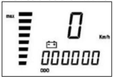
text_image
max 0 Km/h 0000000 ODOWhen the vertical bar blinks and max is displayed, the battery voltage exceeds 14.5 V. If the indication persists, the cause will have to be determined. Contact an authorized Belamotor dealer.
BATTERY ICON - Vb LESS THAN 10.5 V
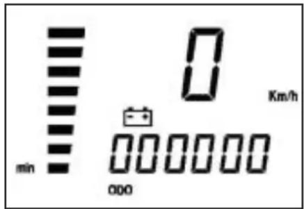
text_image
min 0 Km/h 000When the vertical bar blinks and min is displayed, the battery voltage is less than 10.5 V. If the indication persists, the cause will have to be determined.
IMPORTANT: If the battery is disconnected or its voltage is nearly zero, the instrument loses its functionality. When this happens, the indicator and/or stand warning lights light up and the LCD displays is lit with no symbols. To restore the functionality of the instrument, unplug the connector or disconnect the battery positive terminal for at least 5 seconds. As a result, the clock will lose its setting and the time will have to be set again.
All the other data are preserved.
50.1 Checking the active contents of the monitoring icons
It is always possible to check how many hours are to elapse or kilometres to be covered before the monitoring icons are displayed.
Turn on the instrument while pressing MODE and SCROLL at the same time.
Holding down the buttons for about 5 seconds alternately displays the oil icon with the hours to the next oil change and the service icon with the hours to elapse or the kilometres to be covered (depending on the selected unit) before the vehicle requires servicing. The test begins when the two buttons are released.
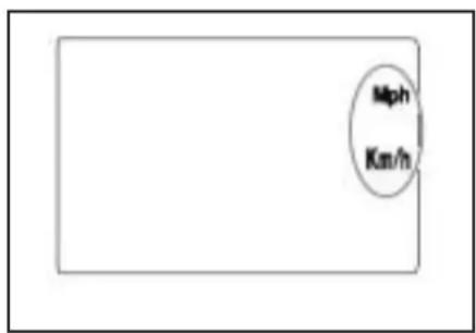
text_image
Mph Km/hSELECTING Km/h or Mph
Press and hold down the SCROLL button until the bars ---- are displayed. When the button is released, only a flashing Km/h or Mph will be displayed to denote which unit is active at the moment.
Briefly press SCROLL to toggle between units.
To confirm the current selection, press and hold down the SCROLL button until WS is displayed in the bottom right corner. When the button is released, the figure is displayed again.
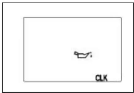
text_image
CLKPressing SCROLL briefly brings up the figure at left.
SPECIFICATIONS
MAXIMUM LOAD
rider + passenger.... 280 kg
VEHICLE'S KERB (DRY) WEIGHT ALP200 103 kg
VEHICLE'S KERB (DRY) WEIGHT ALP125 101 kg
DIMENSIONS
overall length 2,143 mm
overall width 820 mm
overall height 1,170 mm
wheelbase 1,372 mm
saddle height 836 mm
ground clearance.... 288 mm
FRAME.... steel, double closed cradle
TYRES
type.... Michelin - Trial Competition TT
pressure bar front 0.8 / rear 0.6
full-load pressure bar.... front 1.3 / rear 1.3
size ...... front 2.75 - 21" / rear 4.00 - 18"
type.... PIRELLI Scorpion
pressure bar ...... front 1.6 / rear 1.8
full-load pressure bar.... front 2.0 / rear 2.4
size ...... front 90/90 - 21" / rear 120/80 - 18"
CAPACITIES
fuel tank 6.8 l
including reserve 1.5
engine oil 850 cc
average consumption.... 25 km/l
1
FRONT SUSPENSION
Hydraulic fork with ∅ 38 mm rods, adjustable rebound and spring preload Leg oil capacity:
left 350 cc
right 350 cc
Oil type Bel Ray MC 10 SAE 10
or LIQUI MOLY RECING SUSPENSION OIL SAE 10W
Oil level 120 mm from tube upper rim
with fork at end of travel and no spring
Trail 170 ± 3 mm
REAR SUSPENSION
Single progressive hydraulic shock absorber with adjustable rebound and spring preload
shock absorber travel 80 mm
FRONT BRAKE
∅ 220 mm disc brake with hydraulic control
REAR BRAKE
∅ 220 mm disc brake with hydraulic control
ENGINE ALP 125
Type ...... Single-cylinder, forward-inclined, four-stroke, SOHC
Bore x stroke 54X54 mm
Displacement 124 cc
Compression ratio 10:1
Carburettor .....MIKUNI UCAL 5Nh ∅ 26-38
Lubrication oil in sump
Fuel system .... petrol (unleaded, with a minimum octane number of 95), by carburettor
Cooling system by air circulation
Spark plug NGK DR7 HSA
Clutch .... multiple-disc in oil bath
transmission 5-speed, with constant-mesh gears
Primary gearbox ratio 68/20
Final gearbox ratio 60/14
Gear ratios 1st 37/14
2nd.... 32/18
3rd 25/19
4th....23/22
5th....21/24
Drive chain ...... REGINA DERVIO 1/2, 5/15 P. 138
Play of valves ...... intake mm 0.08 - 0.12 , exhaust mm 0,10 - 0,14
Starting .... electric and/or kick-start
Engine oil BARDAHL XTM15W 50
Engine oil capacity.... 1,000 ml/1,050 ml
1
ENGINE ALP 200
Type ...... single-cylinder, four-stroke SUZUKI H402
Bore x stroke 66 x 58.2
Displacement 199 cc
Compression ratio 9.4:1
Carburettor MIKUNI BST31 42AD
Lubrication oil in sump
Fuel system .... petrol (unleaded, with a minimum octane number of 95), by carburettor
Cooling system by air circulation
Spark plug NGK DR8 EA
Clutch multiple-disc in oil bath
Transmission 5-speed, with constant-mesh gears
Primary gearbox ratio 3.157 (60/19)
Final gearbox ratio 3.200 (48/15)
Gear ratios 1st 3.000 (33/11)
2nd....1.933 (29/15)
3rd 1.437 (23/16)
4th....1.095 (23/21)
5th....0,913 (21/23)
Drive chain ...... REGINA DERVIO 135 EBXL - 112-link w/joint
Play of valves....intake and exhaust 0.08-0.13 mm
Starting .... electric and/or kick-start
Engine oil BARDAHL XTM15W 50
Engine oil capacity.... oil change 850 ml with filter replacement 950 ml
overhaul 1300 ml
flowchart
graph TD
    A["1"] --> B["2"]
    B --> C["3"]
    C --> D["4"]
    D --> E["5"]
    E --> F["6"]
    F --> G["7"]
    G --> H["8"]
    H --> I["9"]
    I --> J["10"]
    J --> K["11"]
    K --> L["12"]
    L --> M["13"]
    M --> N["14"]
    N --> O["15"]
    O --> P["16"]
    P --> Q["17"]
    Q --> R["18"]
    R --> S["19"]

    subgraph Power Line
        T["1"] --> U["2"]
        U --> V["3"]
        V --> W["4"]
        W --> X["5"]
        X --> Y["6"]
        Y --> Z["7"]
        Z --> AA["8"]
        AA --> AB["9"]
        AB --> AC["10"]
        AC --> AD["11"]
        AD --> AE["12"]
        AE --> AF["13"]
        AF --> AG["14"]
        AG --> AH["15"]
        AH --> AI["16"]
        AI --> AJ["17"]
        AJ --> AK["18"]
        AK --> AL["19"]

    subgraph Relays
        AM["1"] --> AN["2"]
        AN --> AO["3"]
        AO --> AP["4"]
        AP --> AQ["5"]
        AQ --> AR["6"]
        AR --> AS["7"]
        AS --> AT["8"]
        AT --> AU["9"]
        AU --> AV["10"]
        AV --> AW["11"]
        AW --> AX["12"]
        AX --> AY["13"]
        AY --> AZ["14"]
        AZ --> BA["15"]
        BA --> BB["16"]
        BB --> BC["17"]
        BC --> BD["18"]
        BD --> BE["19"]

    subgraph meters
        BF["20"] --> BG["21"]
        BG --> BH["22"]
        BH --> BI["VNe"]
        BI --> BJ["VMe"]
        BJ --> BK["D-Ne"]
        BK --> BL["D-Ne"]
        BL --> BM["BP"]
        BM --> BN["Rc-Cr"]
        BN --> BO["D-Ne"]
        BO --> BP["D-Ne"]
        BP --> BQ["D-Ne"]
        BQ --> BR["D-Ne"]
        BR --> BS["D-Ne"]
        BS --> BT["D-Ne"]
        BT --> BU["D-Ne"]
        BU --> BV["D-Ne"]
        BV --> BW["D-Ne"]
        BW --> BX["D-Ne"]
    end

    subgraph Capacitors
        C0["Cu-Na"] --> C1["Cu-Na"] & C2["Cu-Na"] & C3["Cu-Na"] & C4["Cu-Na"] & C5["Cu-Na"] & C6["Cu-Na"] & C7["Cu-Na"] & C8["Cu-Na"] & C9["Cu-Na"] & C10["Cu-Na"] & C11["Cu-Na"] & C12["Cu-Na"] & C13["Cu-Na"] & C14["Cu-Na"] & C15["Cu-Na"] & C16["Cu-Na"] & C17["Cu-Na"] & C18["Cu-Na"] & C19["Cu-Na"] & C20["Cu-Na"] & C21["Cu-Na"] & C22["Cu-Na"] & C23["Cu-Na"] & C24["Cu-Na"] & C25["Cu-Na"] & C26["Cu-Na"] & C27["Cu-Na"] & C28["Cu-Na"] & C29["Cu-Na"] & C30["Cu-Na"] & C31["Cu-Na"] & C32["Cu-Na"] & C33["Cu-Na"] & C34["Cu-Na"] & C35["Cu-Na"] & C36["Cu-Na"] & C37["Cu-Na"] & C38["Cu-Na"] & C39["Cu-Na"] & C40["Cu-Na"] & C41["Cu-Na"] & C42["Cu-Na"] & C43["Cu-Na"] & C44["Cu-Na"] & C45["Cu-Na"] & C46["Cu-Na"] & C47["Cu-Na"] & C48["Cu-Na"] & C49["Cu-Na"] & C50["Cu-Na"] & C51["Cu-Na"] & C52["Cu-Na"] & C53["Cu-Na"] & C54["Cu-Na"] & C55["Cu-Na"] & C56["Cu-Na"] & C57["Cu-Na"] & C58["Cu-Na"] & C59["Cu-Na"] & C60["Cu-Na"] & C61["Cu-Na"] & C62["Cu-Na"] & C63["Cu-Na"] & C64["Cu-Na"] & C65["Cu-Na"] & C66["Cu-Na"] & C67["Cu-Na"] & C68["Cu-Na"] & C69["Cu-Na"] & C70["Cu-Na"] & C71["Cu-Na"] & C72["Cu-Na"] & C73["Cu-Na"] & C74["Cu-Na"] & C75["Cu-Na"] & C76["Cu-Na"] & C77["Cu-Na"] & C78["Cu-Na"] & C79["Cu-Na"] & C80["Cu-Na"] & C81["Cu-Na"] & C82["Cu-Na"] & C83["Cu-Na"] & C84["Cu-Na"] & C85["Cu-Na"] & C86["Cu-Na"] & C87["Cu-Na"] & C88["Cu-Na"] & C89["Cu-Na"] & C90["Cu-Na"] & C91["Cu-Na"] & C92["Cu-Na"] & C93["Cu-Na"] & C94["Cu-Na"] & C95["Cu-Na"] & C96["Cu-Na"] & C97["Cu-Na"] & C98["Cu-Na"] & C99["Cu-Na"] & D00["Cu-Na"]
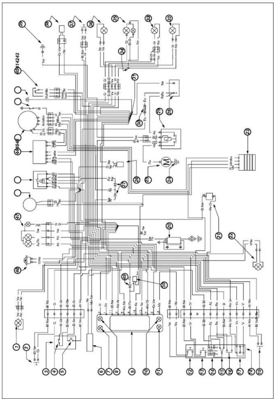
WIRING DIAGRAM ALP 125
1) RIGHT-HAND FRONT TURN INDICATOR (12V-10W BULB)
47) HEADLIGHT WITH 12V-35/35W BULB AND 12V-5W PARKING LIGHT BULB
48) 12V HORN
49) 1A DIODE
50) HEADLIGHT WITH 12V-35/35W BULB AND 12V-5W PARKING LIGHT BULB
51) 12V HORN
Key to colours
| Bi = White | Bl = Blue | Ar = Orange |
| Ve = Green | Ne = Black | Az = Sky-blue |
| Ma = Brown | Gi = Yellow | Ro = Pink |
| Vi = Purple | Rs = Red | Gr = Grey |
ELECTRICAL DEVICES
BATTERY
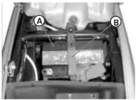
Togain access to battery (A), remove the saddle as described on page 138. Release rubber band (B), disconnect the cables and remove the battery.
WARNING
To prevent damage to the electrical system, never disconnect the cables while the engine is running. Reinsert battery (A) in the specially designed recess under the saddle and fasten it using rubber band (B). Connect the terminal on the black cables to the battery negative (-) terminal and the two red cables to the battery positive (+) terminal, fitting the protective cap as shown in the figure.
text_image
A B
text_image
TO BATTERY POSITIVE (+) TERMINAL (red cables) TO BATTERY NEGATIVE (-) TERMINAL (black cables) POSITION OF BATTERY PROTECTION1
ELECTRONIC CONTROL UNIT - STARTING RELAY - VOLTAGE REGULATOR
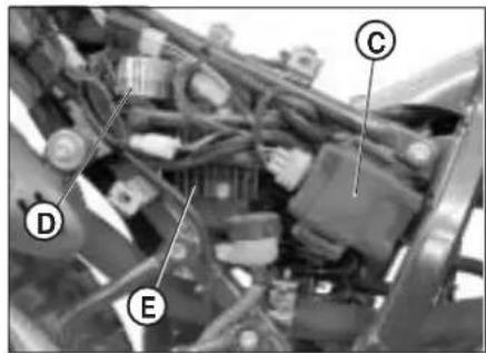
Control unit (C), starter relay switch (D) and voltage regulator (E) are located on the right side of the vehicle. To have access to these components, remove the saddle and the rear side panel as described on page 138.
text_image
Labeled mechanical assembly diagram showing components A, B, C, D, and E with visible wiring and componentsHV COIL
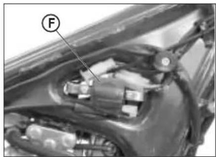
To gain access to coil (F), remove the fuel tank as described on page 138.
natural_image
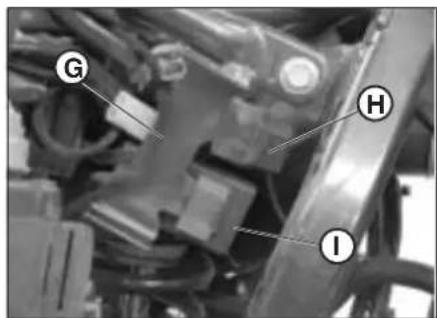
Close-up of a car's head and engine compartment with labeled component (F), no visible text or symbols beyond the label.FUSE - FLASHER UNIT - STAND RELAY Flasher unit (G), stand relay (H) and fuse box (I) are installed under the control unit. To replace any of these components, remove the saddle and the rear side panel as described on page 138, then disengage control unit (C) from its rubber support.
text_image
G H ICONTENTS
CHAPTER 2 OPERATION
Checks and maintenance before and after off-road use Recommended lubricants and fluids
Running-in
Starting the engine
Shutting off the engine
Refuelling
2
CHECKS AND MAINTENANCE OPERATIONS BEFORE AND AFTER OFF-ROAD USE
To avoid trouble during operation, it is advisable to perform a few checks and maintenance operations before and after riding. In addition to making your vehicle safer, a few minutes spent carrying out these operations will enable you to save time and money.
Follow these steps:
TYRES Check the inflating pressures, the general condition, and the tread depth.
SPOKES Check the tensioning.
NUTS AND BOLTS Check the tightening of all nuts and bolts.
DRIVE CHAIN Check the tension (play = 20 mm) and if necessary grease.
AIR FILTER Clean the filter and wet it with oil.
Note
Check for the presence of the vehicle identification papers.
In cold weather, it is advisable to warm up the engine by letting it idle for a few moments before starting off.
The vehicle needs to be carefully washed every time it is used over rough ground.
RECOMMENDED LUBRICANTS AND FLUIDS
To maximize the vehicle's performance and ensure many years of trouble-free operation, we recommend using the following products:
| PRODUCT TYPE SPECIFICATIONS | |
| ENGINE OIL BARDAHL XTM 15W 50 | |
| BRAKE OIL BARDAHL BRAKE FLUID DOT4 | |
| FORK OIL BEL RAY "MC 10 SAE | 10"orLIQUI MOLY RACING SAE 10W |
| TIE ROD GREASE BARDAHL Outboard Grease NLGI2 |
Note
It is essential that all renewals should be performed with the products listed in the table above.
RUNNING-IN
The running-in period lasts approximately 10 hours, during which it is advisable to:
•Warm up the engine well before starting off.
- Avoid riding at constant speed (changing the speed allows the different components to bed in uniformly and in a shorter time).
- Avoid turning the throttle twist grip more than 3/4 of its travel.
WARNING
• After the first 1000 km renew the engine oil.
•Always use high-octane unleaded petrol.
• After using the vehicle on rough ground for the first time, carefully check the tightening of all nuts and bolts.
2
STARTING THE ENGINE
- Turn the key in the ignition key clockwise and ensure that the neutral indicator on the instrument panel is lit (see item 5 on page 93).
- Set the emergency switch on the throttle control to the (o) position.
- Turn fuel cock A:
$$ \text { OFF } = \text { closed } $$
$$ O N = o p e n $$
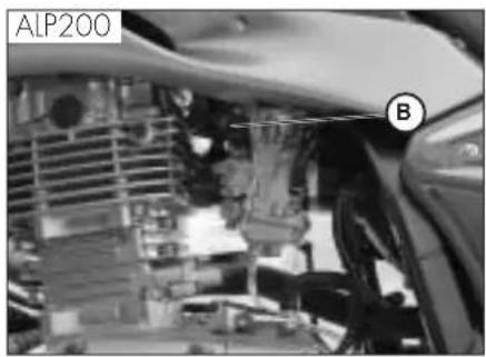
- Pull out starting device knob B, located on the left side of the carburettor, until the second click is heard.
- On ALP125 models, starter lever B can only be operated after pressing it inwards.
- Pull the clutch lever while pushing the start button on the throttle control without rotating the throttle twist grip (vehicles with electric start only).
natural_image
Close-up of a mechanical assembly with labeled component A, no readable text or symbols present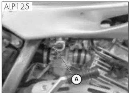
text_image
ALP125 AWarning:
If a backward-shifted footrest kit is fitted (for trial use), lift the right-hand footrest to allow the rotation of the kick-start.
- Wait for about 2 minutes to warm up the engine without rotating the throttle twist grip, and then push down starting device B, pausing after the first click.
Note:
The engine can also be started when the stand is down provided that the neutral indicator is lit.
text_image
ALP200 B
text_image
ALP125 BImportant
When the stand is down, the red warning light on the instrument panel stays lit and the engine stops for safety reasons as soon as the gears are engaged, even if the clutch lever is pulled.
Always retract the stand before putting into gear.
Note
In an emergency, the vehicle can also be operated without a battery.
SHUTTING OFF THE ENGINE
- While the vehicle is stationary and in neutral gear, rotate the ignition key to the "OFF" position.
- Before stopping the engine after a long ride, it is advisable to let it idle for a few moments.
•Always close the fuel cock after stopping the engine.
2
natural_image
Mechanical component diagram showing a housing with labeled part A (no text or symbols beyond label)REFUELLING
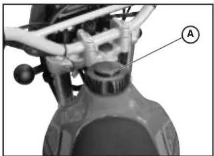
- Switch off the engine.
- Remove cap A.
Note
The fuel tank capacity is approximately 6.8 litres, including 1.5 litres reserve.
Any spills of petrol on the bodywork or other parts of the motorcycle must be removed immediately.
Shut off the engine before refuelling. Petrol is extremely flammable. Take care not to spill any petrol from the tank or while refuelling.
Do not keep open flames or lighted cigarettes close to the fuel filler: fire hazard. Also avoid inhaling noxious fumes.
GB
CONTENTS
CHAPTER 3 CHECKS AND MAINTENANCE
Engine oil and oil filter
Fume collecting tube
Brake pump oil - Bleeding the brakes
Fork oil
Air filter
Spark plug
Front and rear brakes
Battery
Removing the bodywork
Notes for trial use
Cleaning and checking the vehicle
Scheduled maintenance
Prolonged inactivity
3
CHECKS AND MAINTENANCE
text_image
B G AENGINE OIL AND OIL FILTER ALP 200
Check
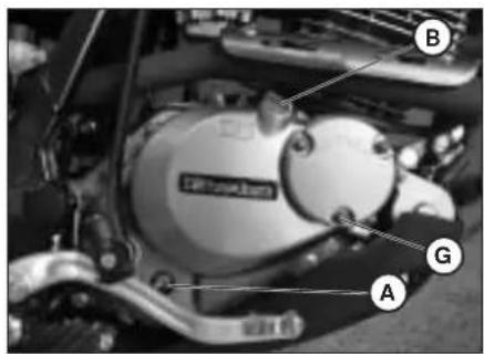
Keep the vehicle in an upright position. Check the oil level through oil level sight A when the engine is cold. The oil level must never fall below the sight. If necessary, top up after removing filler cap B.
Topping up
Only top up after checking the max level shown on sight A.
text_image
E C D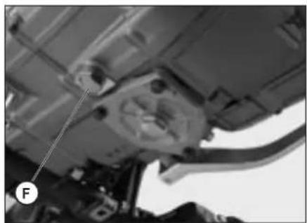
natural_image
Close-up of a mechanical assembly with visible components and a labeled force arrow (no text or symbols)Renewal
Always renew the oil when the engine is hot. To avoid burns, take care not to touch the engine and the oil.
- The oil filter should be renewed at the same time as the oil.
- Put the vehicle on its stand.
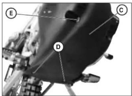
- Extract the two screws D and fastening E, and then remove protection C.
- Place a container under the engine.
- Unscrew filler plug B and drain plug F.
- Drain all the oil from the crankcase.
- Close plug F.
- Remove the oil filter cover after unscrewing the three nuts G.
- Remove the oil filter and replace it with a new one.
- Apply a thin film of engine oil to the filter cover O-ring before insertion.
- Apply a film of engine oil over the filter cover O-ring before fitting it.
GB
- Fit the oil filter cover after fitting the spring and the O-ring, and then tighten the three fastening nuts.
- Pour in the necessary quantity of oil.
- Close the filler plug and then refit the protection taking care to position the spacers in sequence.
- Start the engine and allow it to idle for a few minutes.
- Switch off the engine, wait for about a minute, and then check the level. If necessary top up without exceeding the max level.
Engine oil capacity:
oil change 850 ml
with filter replacement 950 ml
overhaul 1,300 ml
Note
Renew the oil after the first 1,000 km. Subsequent renewals should be every 5,000 km 15 months, (refer to the table on page 142). Always use the lubricants shown on page 123.
The oil filter should be replaced for the first time when the oil is first renewed, and subsequently every 10,000 km (30 months).
Important
Dispose of used oil in compliance with the regulations in force.
3
ENGINE OIL AND OIL FILTER ALP 125
Check
Keep the vehicle in an upright position.
The engine is cold, check for the presence of oil.
Topping up
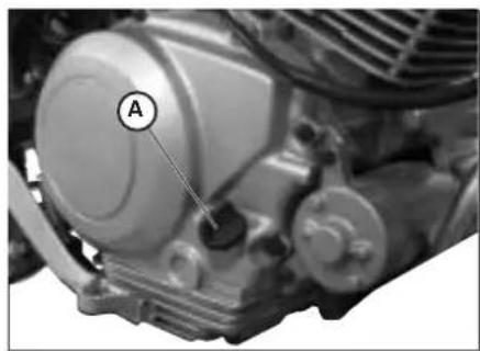
To restore the level, remove cap A and top up.
Renewal
Always renew the oil when the engine is hot. To avoid burns, take care not to touch the engine and the oil.
- Put the vehicle on its stand.
- Extract the two screws D and fastening E, and then remove protection C.
- Place a container under the engine.
- Unscrew filler plug A and drain plug B.
- Drain all the oil from the crankcase.
- Close plug B.
• Pour in 1000 cc of fresh oil. - Screw on filler cap A again.
WARNING
Hot oil can cause severe burns.
Note:
Renew the engine oil after the first 500 km. For the renewal intervals, refer to the table on page 142. Only use the lubricants
recommended on page 123.
natural_image
Close-up of a mechanical engine component with labeled part 'A' (no other text or symbols visible)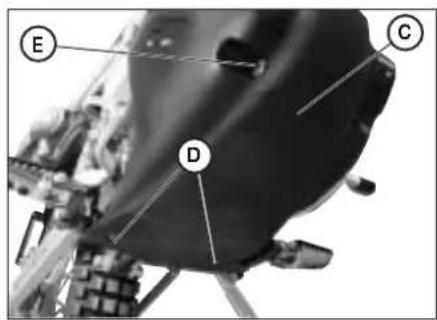
text_image
Labeled diagram of a spacecraft or spacecraft interior with marked points E, C, and D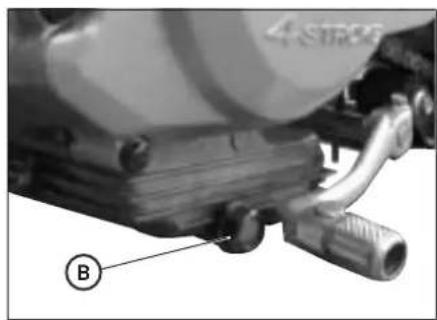
natural_image
Close-up of a mechanical component with labeled parts (B) and no visible text or symbols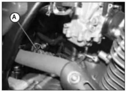
natural_image
Close-up of a mechanical assembly with labeled component A (no visible text or symbols)FUME COLLECTING PIPE
Fume collecting tube A is located on the left side of the vehicle next to the shock absorber. It comes out of the lower part of the filter box and is designed to collect the fumes produced by the engine oil. It is designed to collect the fumes produced by the engine oil. Should any oil be found in the tube, remove the cap at the lower end of the tube and drain the oil, or the mixture of oil and petrol, into a suitable container. Disposal is to be made according to the regulations in force.
Note Empty the fume collecting tube every 3,000 km.
BRAKE PUMP OIL - BLEEDING THE BRAKES
Front brake
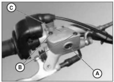
Check that oil is present by looking through oil level sight A. The minimum oil level should never be lower than the mark on sight A. To restore the oil level, loosen the two screws B, lift cover C and pour in fresh oil.
Rear brake
Check that oil is present by looking through reservoir D. The oil level must never be lower than the minimum level mark on reservoir D. To restore the level, remove filler cap E and top up with fresh oil.
WARNING
A spongy feel of the brake lever may be due to an air bubble in the braking system. Immediately contact an authorized workshop.
Note
For information on oil renewals, refer to the table on page 142. Use the recommended lubricants shown on page 123.
text_image
Labeled mechanical component diagram showing parts A, B, and C with visible wiring and adjustment knobs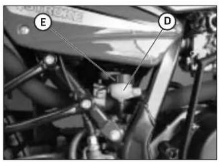
text_image
E D3
Bleeding the front brake
Follow these steps to bleed the front brake circuit:
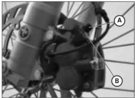
- Remove rubber cap A from valve B.
- Remove the oil reservoir cap.
- Insert one end of a small tube into valve B and place the other end in a container.
- Unscrew valve B (while pulling the lever) and then pump by repeatedly actuating the brake lever until oil starts flowing out continuously with no air bubbles. During this operation, it is important that the lever should not be released completely and that the brake pump reservoir should be continuously refilled to make up for the oil that is flowing out.
•Tighten the valve and extract the tube.
-Replace the cap.
natural_image
Close-up of a bicycle's wheel assembly with labeled parts A and B (no text or symbols beyond labels)Bleeding the rear brake
Follow these steps to bleed the rear brake circuit:
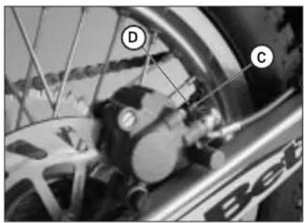
- Remove rubber cap C.
- Remove the oil reservoir cap.
- Insert one end of a small tube into valve D and place the other end in a container.
- Unscrew valve D (while pulling the lever) and then pump by repeatedly actuating the brake lever until oil starts flowing out continuously with no air bubbles. During this operation, it is important that the lever should not be released completely and that the brake pump reservoir should be continuously refilled to make up for the oil that is flowing out.
• Tighten the valve and extract the tube.
-Replace the cap.
text_image
Close-up of bicycle wheel components with labeled parts D and C, showing mechanical assembly and brandingGB
text_image
B AFORK OIL
Right-hand rods
The procedure for changing the oil in the forks is provided only for information. We recommend having the operation performed by a BETAMOTOR authorized workshop.
Follow these steps to renew the oil:
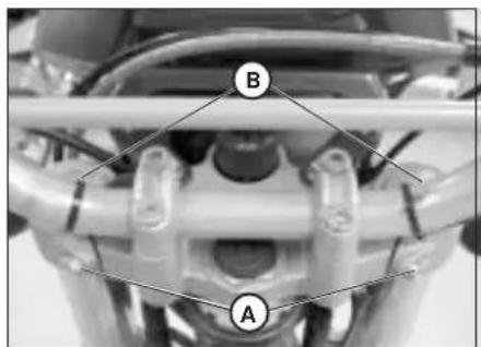
1) Loosen rod clamping screw A
2) Remove the lower plug (Allen screw in the legging) and upper plug B.
3) Let all the oil drain from the rod.
4) Fit and tighten the legging lower plug.
5) Pour in fresh oil of the type shown in the table on page 123.
6) Fit and tighten upper plug B.
7) Retighten rod clamping screw A.
Note: The oil change procedure applies to both the left and the right fork legs.
3
CHECKS AND MAINTENANCE
natural_image
Close-up of a motorcycle seat with a circular mark and label D pointing to the side (no text or symbols on the body)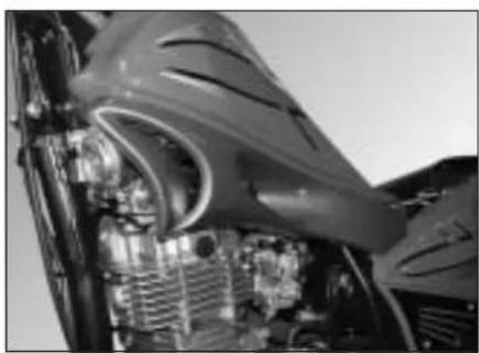
natural_image
Close-up of an aircraft engine bay with visible internal components and structural details (no text or symbols)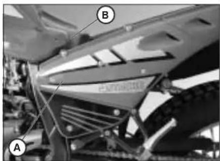
text_image
A B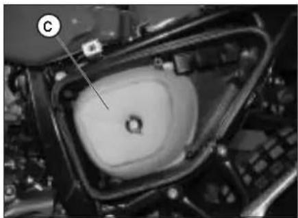
natural_image
Close-up of a mechanical component with a labeled section (C), showing internal structure and mounting hardware (no readable text or symbols)AIR FILTER
Follow these steps to gain access to the air filter.
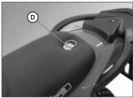
- Turn fastener D 90 degrees anticlockwise and remove the saddle by pulling it towards the back of the vehicle. - Remove side panel B after unscrewing the screws shown in the figure. - Take off plastic cover A after unscrewing the 7 fixing screws, then follow these steps:
- Unscrew the filter cover fixing screw and remove filter C. - Wash it with soap and water.
- Dry the filter.
- Wet the filter with filter oil. Remove any excess lubricant to prevent it from dripping.
- If necessary, also clean the inside of the filter casing.
- Refit the parts, making sure of the seal of the rubber gasket.
Note: If the filter is very dirty, first wash it with a special detergent and then with water and shampoo. If the filter is damaged, immediately replace it.
WARNING:
After working on the filter, ensure that nothing is left inside the filter casing.
Clean the filter every time the vehicle is used off road.
GB

To avoid burns, put on protective gloves before performing the operation.
Keeping the spark plug in good condition makes for reduced consumption and optimum engine performance.
It is advisable to remove the spark plug when the engine is hot (and naturally off) because the carbon formation and the colour of the insulator provide important information on carburetion, lubrication, and the general condition of the engine. If the insulator appears white, the mixture is probably too lean; conversely, a green insulator denotes a rich mixture. The mixture is correct when the insulator is tan coloured.
To carry out the check, simply remove the current cap and then unscrew the spark plug using the spanner provided.
Carefully clean the electrodes using a wire brush. Blow the spark plug with compressed air to prevent any residues from getting into the engine.
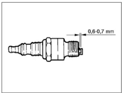
Measure the spark gap with a thickness gauge. The gap should be 0.6-0.7 mm. If the gap is not as specified, restore the proper gap by bending the earth electrode.
Check that the insulator is not cracked and that the electrodes are not corroded, in which case the spark plug should be immediately replaced.
Conduct the check by referring to the table on page 142.
text_image
0,6-0,7 mmLubricate the spark plug thread, and then (when the engine is cold) screw in the spark plug by hand to its abutting end. Finally tighten the spark plug with the spanner.
Note
• Always use NGK DR8 EA spark plugs.
natural_image
Close-up of industrial machinery components (no visible text or symbols)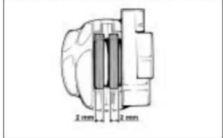
text_image
2 mm 2 mm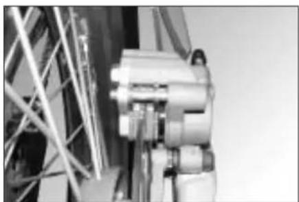
natural_image
Close-up of industrial machinery components (no visible text or symbols)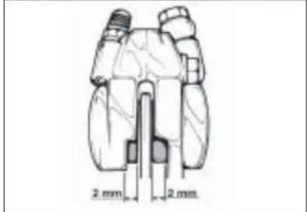
text_image
2 mm 2 mmFRONT BRAKE
Check
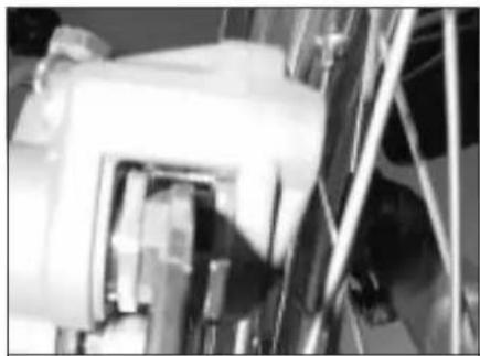
To check the wear of the front brake, visually inspect the brake pad ends by looking at the brake caliper from the front. The brake linings should be at least 2 mm thick. If the linings are thinner, replace the pads immediately.
Note
Carry out the check at the intervals shown in the table on page 142.
REAR BRAKE
Check
To check the wear of the rear brake, visually inspect the brake pad ends by looking at the brake caliper from above. The brake linings should be at least 2 mm thick. If the linings are thinner, replace the pads immediately.
Note
Carry out the check at the intervals shown in the table on page 142.
BATTERY
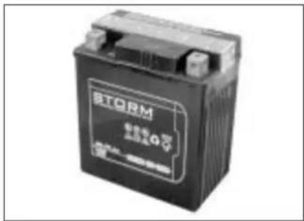
Check the charge of the battery by measuring the voltage with a voltmeter while the battery is at rest (engine off). The voltage must not be less than 12.8 V. There is no need to check the level of the electrolyte or top up with water. Keep the battery terminals clean. If necessary, protect them with a thin film of acid-free grease.
text_image
BTORM 正弦器Q号 BPTC-20000000000000000000000000000000000000000000000000000000000000000000000000000000000000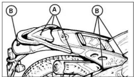
text_image
A B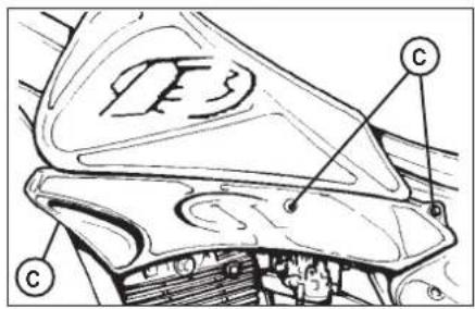
text_image
Technical diagram of a mechanical component with labeled parts C and C1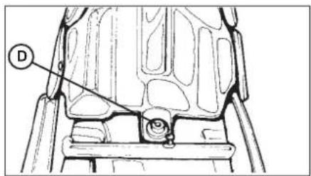
text_image
Technical diagram of a mechanical component with labeled part D and a circular marker.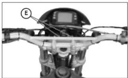
natural_image
Close-up of a robotic device with labeled component E, showing internal wiring and mechanical components (no readable text or symbols)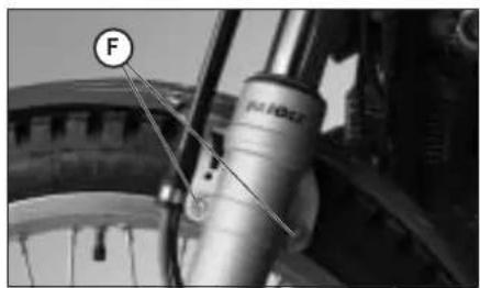
text_image
F P1002REMOVING THE BODYWORK
To facilitate checks and operations in certain areas of the vehicle, it is essential to remove the bodywork sections as described below.
Removing the saddle
Remove the screw fixing the saddle to the mudguard and then remove the saddle by pushing it towards the rear of the vehicle so as to disengage it from the hook on the fuel tank.
Removing the carrier
Remove the three screws A fixing the carrier to the mudguard and then remove the carrier.
Removing the side panel
After removing the air filter cover as described in the chapter "Air Filter", unscrew the four fixing screws B. One of the screws is on the left side (under the filter box cover) whereas the rear screw is located underneath the mudguard cover (not in view).
Removing the front side panels
Remove the six fixing screws C (three on each side), two of which located under the fuel tank, and then remove the front side panels.
Removing the fuel tank
Remove screw D fixing the fuel tank to the frame, detach the fuel cock line and then remove the tank by pulling it towards the rear of the vehicle.
Removing the headlight
Detach all the electrical connections and unscrew the three fixing screws E, one of which located under the headlight.
NOTES FOR TRIAL USE
If the vehicle is to be used over rough ground, the customer may want to remove the number-plate holder, the stand, the passenger's footrests, replace the front sprocket supplied with the kit, and fit backward-shifted rider's footrests.
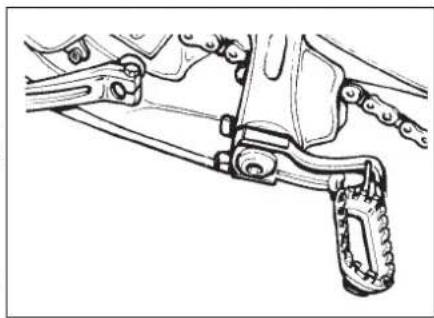
Replacing the rider's standard footrests with backward-shifted footrests (trial)
- Remove the footrests from their supports after unscrewing the M8 bolts.
- Remove the footrest supports by unscrewing the Allen screws.
- Fit the trial footrest supports and then the footrests by following the reverse procedure to the removal.
Removing the number-plate holder
- Remove screw A fixing the number-plate holder to the rear mudguard.
- Remove the three screws B fixing the number-plate holder to the frame from the lower part of the holder.
- Detach the rear light electrical connection and remove the number-plate holder.
Removing the stand
- Remove the stand switch by unscrewing the only fixing screw C.
- Loosen the two screws D fixing the stand support to the frame and then remove the stand.
Removing the passenger's footrests
- Loosen the two screws E shown in the figure and remove the passenger's foot-rest complete with the frame fixing support.
natural_image
Technical line drawing of a mechanical lever assembly (no text or symbols)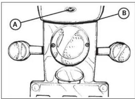
text_image
Technical diagram of a mechanical component with labeled parts A and B, showing internal components and mounting points.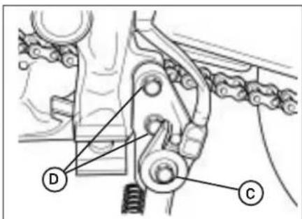
text_image
Technical diagram of a mechanical assembly with labeled components D and C
text_image
E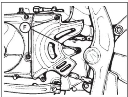
text_image
FReplacing the front sprocket
A description of the procedure for replacing the front chain sprocket is provided for information purposes only. The operation should always be performed by an authorized BETAMOTOR dealer.
- Loosen the rear wheel.
- Loosen the chain adjusters.
- Move the wheel forward to the end of its travel to allow the slackening of the chain.
- Remove the three chain guard fixing screws F (2 screws for ALP125 models).
- Remove the chain from the sprocket.
- Engage the bottom gear and turn the sprocket locknut anticlockwise.
- Replace the sprocket.
- To reassemble, follow the same procedure in reverse order.
Swing arm pivot
- Remove the rubber cap located on the driver's r.h. footboard.
- Unscrew the nut below and pull out the pin on the other side.
WARNING:
The removal of the number-plate holder and the rear light is allowed only if the vehicle is to be used on privately owned ground or on tracks.
Note:
We recommend replacing the front sprocket along with the whole drive unit.
CLEANING AND CHECKING THE VEHICLE
Use a low-pressure water jet to soften the dirt and mud accumulated on the paintwork, then remove them with a soft bodywork sponge soaked in water and shampoo (2-4 percent shampoo in water). Rinse generously with water and wipe dry with chamois leather. For the outside of the engine use a brush soaked in petroleum and clean rags. Petroleum damages the paintwork. Always wash the vehicle before waxing it with silicon waxes.

Detergents pollute the waters. Always wash the vehicle in areas equipped for the collection and purification of the washing liquids.

Never wash the vehicle in the sun, particularly during the summer when the bodywork is hot. The shampoo would dry before being rinsed off and cause ge to the paintwork. Do not clean the plastic surfaces with cloths soaked in or naphtha as they would lose their shine and mechanical properties.
CHECKS AFTER CLEANING
After cleaning the motorcycle, it is advisable to:
- Clean the air filter (refer to the procedure described on page 134).
- Grease the chain.
SCHEDULED MAINTENANCE
| 4-Stroke MotorcyclesAlp125/200 | end of running-in1,000 km | 1st service 5,000 km | 2nd service 10,000 km | 3rd service 15,000 km | 4th service 20,000 km | 5th service 25,000 km | 6th service 30,000 km | 7th service 35,000 km |
| engine | spark plug ch r ch r ch r ch | ||||||||
| engine oil filter cl cl cl r cl r cl | |||||||||
| clutch ch ch ch r ch c | h | ch | |||||||
| play of valves ch ch c h c h c h c h c h c h c h | |||||||||
| engine oil and oil filter r r r r r r r r r | |||||||||
| idle speed adjustment ch ch ch ch ch ch ch ch | |||||||||
| engine oil lines | ch ch ch ch ch ch ch ch | ||||||||
| cycle parts | rear shock absorber | ch | ch | ch | ch | ||||
| battery | ch | ch | ch | ch | |||||
| nuts and bolts* | t | tttttt | |||||||
| steering bearings and steering play | ch | ch | ch | ch | ch | ||||
| air filter | clean every 1,000 km | r | r | r | |||||
| front fork | ch | ch | ch | ch | |||||
| electrical system | ch | ch | ch | ch | ch | ||||
| braking system | ch | ch | ch | ch | ch | ||||
| brake fluid (renew every 2 years) | ch | ch | ch | ch | ch | ||||
| drive chain | clean every 1,000 km | ||||||||
| tyre condition and pressure | ch | ch | ch | ch | ch | ||||
| drive chain tension and lubrication (every 1,000 km) | ch | ch | ch | ch | ch | ||||
| brake lines (replace every 2 years) | ch | ch | ch | ch | ch | ||||
| fuel lines (replace every 2 years) | ch | ch | ch | ch | ch | ||||
* Tightening recommended after each off-road ride.
Key
ch - check (clean, adjust, lubricate or replace/renew as necessary)
r - replace/renew
a - adjust
cl - clean
t - tighten
Note
For any service requirements, please contact Betamotor's Authorized Service Network.
PROLONGED INACTIVITY
A few simple operations should be performed to keep the vehicle in good condition whenever it is to remain inactive for a long period (e.g. during the winter):
• Thoroughly clean the vehicle.
- Reduce the tyre pressures by approximately 30 percent, and if possible raise the tyres off the ground.
- Remove the spark plug and pour a few drops of engine oil into the spark plug hole. Make the engine turn a few times by operating the kick-start (where available) and then replace the spark plug.
- Cover the unpainted parts, excepting the brakes and the rubber parts, with a film of oil or spray silicone.
- Remove the battery and keep it in a dry place. Recharge the battery once a month.
- Protect the vehicle with a dust cover.
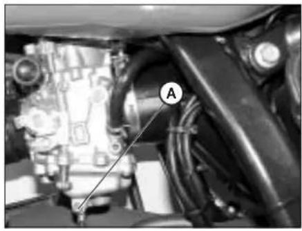
natural_image
Close-up of a mechanical assembly with visible components and a labeled section (A), no readable text or symbols present.- Drain the carburettor float chamber by loosening screw A. The fuel drained from the chamber through a suitable pipe must be collected in a container and poured into the fuel tank. Do not dispose of the fuel in the environment.
- Relighten the screw.
AFTER PROLONGED INACTIVITY
•Reinstall the battery.
- Restore the tyre inflating pressures.
- Check the tightening of all the screws having an important mechanical function.
Note
Periodically check the tightening of the screws.
- Start the vehicle for the first time by means of the kick-start (where available).
CONTENTS
CHAPTER 4 ADJUSTMENTS
Adjusting the brakes
Adjusting the clutch
Adjusting the slow running
Adjusting the throttle play
Checking and adjusting the steering play
Tensioning the chain
Adjusting the headlight
4
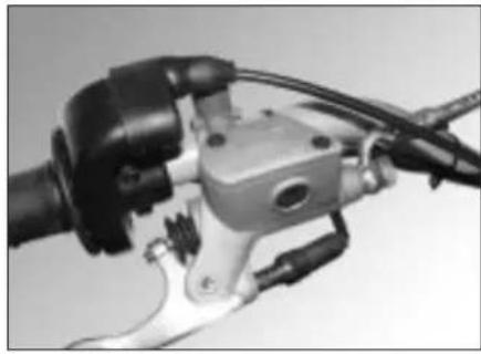
natural_image
Close-up of a mechanical brake lever assembly with hoses and calipers (no visible text or symbols)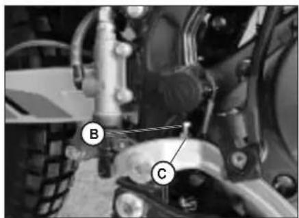
text_image
B C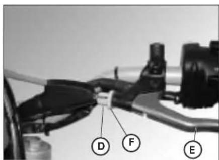
text_image
D F EThe front brake is a hydraulically operated disc brake, and therefore requires no adjustment.
Rear brake
The rear brake is a hydraulically operated disc brake.
The brake pedal can be adjusted for height by means of adjusters B and C.
The brake lever play should never be less than 5 mm.
ADJUSTING THE CLUTCH
The only operation that may be required is the adjustment of the position of clutch lever E.
The adjustment is obtained by means of adjuster D.
After adjusting the lever with the adjusting screw, be sure to tighten stop F so as to lock the screw in the desired position.
Note
The play of the clutch should range from 0.4 to 0.6 mm.
ADJUSTING THE SLOW RUNNING ALP200 The slow running should be adjusted when the engine is hot. Connect an electronic revolution counter to the spark plug cable. Tune up using adjusting screw A (idle speed = 1,400 ± 100 rpm).
ADJUSTING THE THROTTLE PLAY ALP200 If the throttle control idle travel exceeds 3 mm as measured on the rim of the twist grip, adjust the play by acting on adjuster B.
ADJUSTING THE SLOW RUNNING ALP125 The slow running should be adjusted when the engine is hot. Connect an electronic revolution counter to the spark plug cable.
Then turn adjusting screw C with a screwdriver until the engine idles at 1900 rpm.
FUEL FLOW ADJUSMENT ALP125 To adjust the fuel flow, loosen screw D by one and a half turns from the fully closed position.
ADJUSTING THE THROTTLE PLAY ALP125 If the throttle control idle travel exceeds 3 mm as measured on the rim of the twist grip, Perform the adjustment by lifting dust cap F and then turning throttle control ring E as shown in the figure.
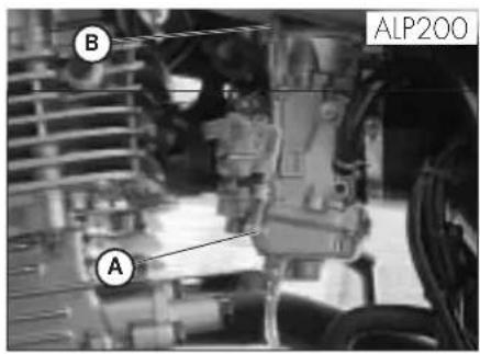
text_image
B ALP200 A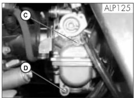
text_image
ALP125 C D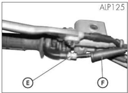
text_image
ALP125 E F4
CHECKING AND ADJUSTING THE STEERING PLAY
Periodically check the play of the steering head tube by moving the forks backwards and forwards as shown in the figure. If any play is felt, carry out the adjustment by following these steps:
•Unscrew the four screws C.
- Pull out handlebar D, paying special attention to clevises E.
- Loosen nut F.
- Reduce the play by turning ring G. To refit the parts, follow the reverse procedure.
Note
Proper adjustment must leave no play and cause no stiffness, and allow the steering to rotate smoothly. Check the fitting direction of the clevises as it can alter the geometry of the handlebar.
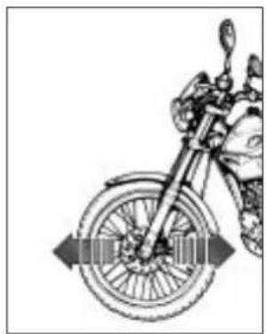
natural_image
Side view of a motorcycle wheel with a directional arrow indicating motion (no text or symbols)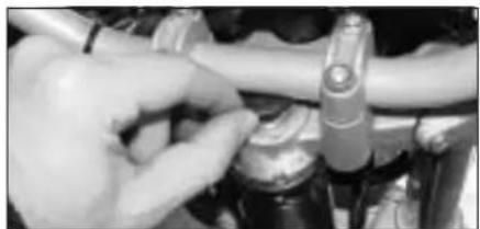
natural_image
Close-up of hands adjusting a mechanical component (no visible text or symbols)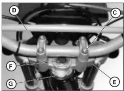
text_image
Labeled mechanical assembly diagram showing components D, C, F, G, and E with connecting rods and tubingGB
TENSIONING THE CHAIN
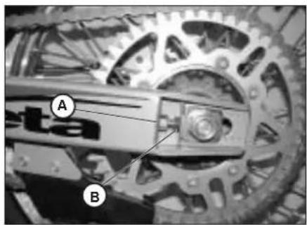
natural_image
Close-up of a mechanical gear assembly with labeled parts A and B (no readable text or symbols beyond labels)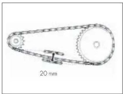
natural_image
Technical line drawing of a mechanical pulley system with 20 mm scale indicator (no text or symbols on the diagram itself)To ensure the drive chain a longer life, it is advisable to periodically check its tension. Always maintain the chain clean and lubricated.
If the chain play exceeds 20 mm, tension the chain by following these steps:
- Loosen the nuts on both sides of the swing arm.
- Turn nut B until the desired chain tension is obtained.
- Perform the same operation on nut B on the other side of the swing arm until the wheel is perfectly aligned.
- Tighten nut A on either side of the swing arm.
4
ADJUSTING THE HEADLIGHT
- The headlight beam is adjusted manually after loosening the screws on either side of the headlight with an Allen key.
- Periodically check the direction of the beam. The beam can only be adjusted vertically.
- Place the vehicle on level ground (but not on the stand) 10 metres from a vertical wall.
- Measure the height of the headlight centre above the ground and then draw a cross on the wall at 9/10 of the height of the headlight centre.
- Turn on the low beam, get on the motorbike and check that the headlight beam on the wall is slightly lower than the cross drawn previously.
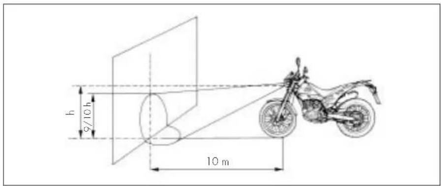
text_image
h 9/10 h 10 mCONTENTS
CHAPTER 5 REPLACEMENTS
Replacing the brake pads
Replacing the headlight bulb
Replacing the rear light bulb
Replacing the turn indicator bulbs
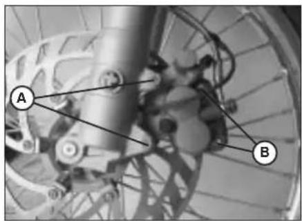
text_image
A B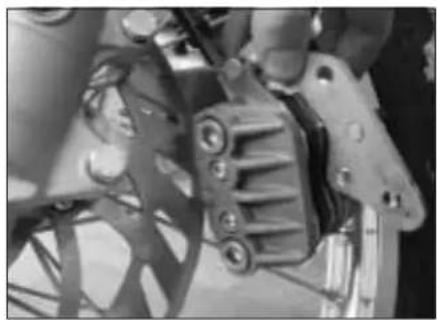
natural_image
Close-up of mechanical components with no visible text or symbols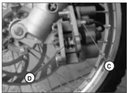
natural_image
Close-up of mechanical components with labeled parts D and C, no readable text or symbols present.The procedure for replacing the brake pads is provided only for information. We recommend having the operation performed by a BETAMOTOR authorized workshop.
Follow these steps to replace the pads:
- Loosen the two screws A and remove the brake caliper.
• Unscrew the two screws B.
Note: Screws B are secured very tightly and should be loosened before removing the caliper from the fork. - Extract the brake pads.
- To refit the parts, follow the reverse procedure.
Ensure that the spring D shown in the figure is properly seated by checking that it offers some resistance to the insertion of the brake pads.
To avoid braking problems, take special care in ensuring that the screws are refitted properly.
Whenever the brake disc is removed, apply Loctite to the screws when refitting
NOTE: When removing the brake caliper, take care not to damage reed C, as it is extremely fragile.
REAR BRAKE
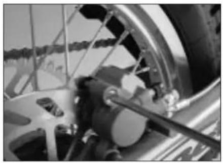
natural_image
Close-up of a bicycle wheel and brake system with visible components (no text or symbols)NOTE: Brake pads should always be replaced by an authorized BETAMOTOR dealer.
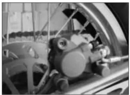
natural_image
Close-up of a car wheel assembly with visible mechanical components (no text or symbols)CHECKING FRETTING
To check the wear of the rear brake, visually inspect the brake caliper from the back. The lining on the visible ends of the two brake pads should be at least 2 mm thick. Should the lining be thinner, immediately replace the brake pads.
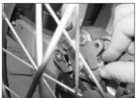
natural_image
Close-up of hands operating a mechanical device with wires and components (no visible text or symbols)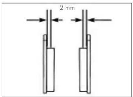
text_image
2 mmREPLACING THE HEADLIGHT BULB
Remove the headlight rim after unscrewing the three fixing screws.
Remove the three reflector fixing screws and pull out the reflector.
Detach the bulb connector.
Rotate the bulb holder anticlockwise and extract the burnt-out bulb.
Fit a new bulb taking care not to touch the bulb to avoid impairing its function. Rotate the bulb holder clockwise to the stop.
Refit the connector, the reflector, and the headlight rim by following the reverse procedure to the removal.
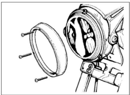
natural_image
Technical line drawing of a mechanical device with circular components and bolts (no text or symbols)REPLACING THE REAR LIGHT BULB
Remove the lens after unscrewing the two fixing screws.
Replace the defective bulb.
The bulbs have bayonet bases. To remove them, press them lightly, rotate them 30^ anticlockwise and then extract them.
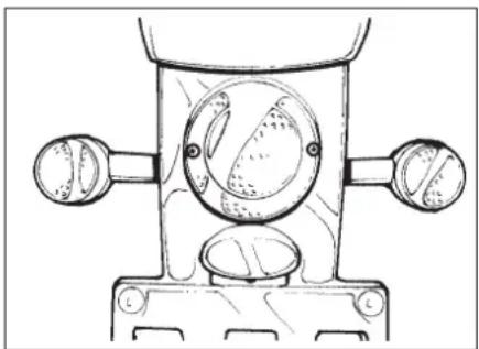
natural_image
Technical line drawing of a mechanical component with circular features and two side ports (no text or symbols)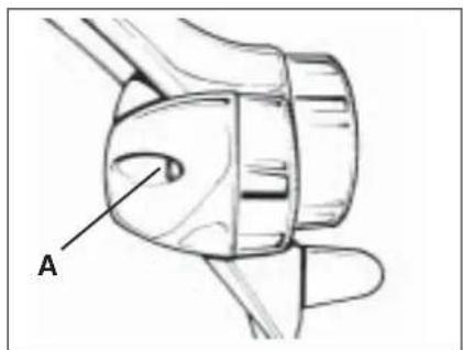
text_image
AREPLACING THE TURN INDICATOR BULBS
Loosen screw A and remove the lens.
CONTENTS
CHARTER 6 TROUBLESHOOTING INDEX
| PROBLEM CAUSE | REMEDY | |
| Engine does not start | -Fuel system clogged (fuel lines, fuel tank, fuel cock). | Clean the system. |
| -Air filter dirty. | Proceed as described on page 134. | |
| -No current supplied to spark plug. | Clean or replace the spark plug. If the problem persists, contact a BETAMOTOR dealer. | |
| -Engine flooded. | Open the throttle wide and try starting the engine for a few moments. If this does not solve the problem, remove the spark plug and dry it. | |
| Engine misfires | -Spark gap wrongly adjusted. | Restore the spark gap. |
| -Spark plug dirty. | Clean or replace the spark plug. | |
| Engine knocks | -Spark advance excessive. | Check the ignition timing. |
| -Carbon formation in cylinder or on spark plug. | Contact a BETAMOTOR dealer. | |
| Engine overheats and loses power | -Silencer partly clogged. | Contact a BETAMOTOR dealer. |
| -Exhaust port clogged. | Contact a BETAMOTOR dealer. | |
| -Ignition delayed. | Check the timing. | |
| Front braking poor | -Brake pads worn. | Follow the procedure described on page 136. |
| -Air or humidity in the hydraulic circuit. | Follow the procedure described on page 131. | |
| Rear braking poor | -Brake pads worn. | Follow the procedure described on page 136. |
| -Air or humidity in the hydraulic circuit. | Follow the procedure described on page 131. | |
Air filter 134
Brake pump oil 131
Brakes, adjustment 146
Brakes, bleeding 131
Bulbs, replacement 154
Chain, tensioning 148
Checks after cleaning 141
Checks and maintenance before and after off-road use 122
Clutch, adjustment 146
Engine oil, check and renewal 128/130
Fork oil.... 133
Front brake, pad check and replacement 136
Helmet lock....92
Ignition switch/Steering lock 92
Instrument panel and controls.... 93
LCD 94
Keys and locks 92
Rear brake, pad check and replacement 136
Recommended lubricants and fluids 123
Refuelling.... 126
Running-in 123
Scheduled maintenance 142
Slow running, adjustment 147
Spark plug 135
Specifications 111
Starting 124
Steering, check and adjustment 147
Throttle play, adjustment 147
Troubleshooting 157
Vehicle identification data 88
Wiring diagrams 113/114
ALP4T 125/200 cc
natural_image
Close-up of mechanical components with visible wiring and a labeled section (A), no readable text or symbols present.DONNÉES D'IDENTIFICATION DU VÉHICULE
natural_image
Close-up of mechanical components with no visible text or symbolsIDENTIFICATION DU MOTEUR ALP 200
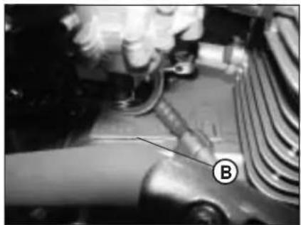
natural_image
Close-up of a mechanical component with labeled parts (B), no readable text or symbols present.EQUIPEMENT
natural_image
Line drawing of a mechanical setup with a tool, two cylindrical components, and a rectangular block (no text or symbols)F
CHARGE
Type: Trial competition TT
text_image
Labeled diagram of a motorcycle with numbered parts for identification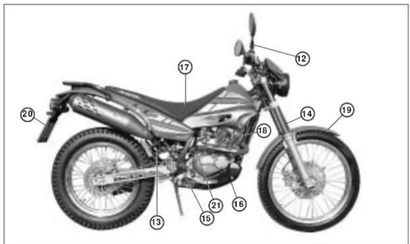
text_image
Labeled diagram of a motorcycle with numbered parts for identificationtext_image
Labeled diagram of a motorcycle body with numbered parts for identification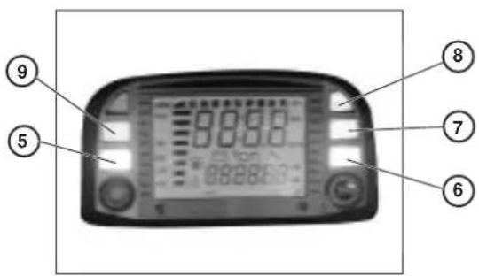
text_image
Labeled diagram of a digital device showing control buttons and display screen with numeric readouts20.0 MISE AU POINT NIVEAU 1
40.0 INDICATIONS SUR ECRAN LCD
text_image
SPEED MAX 88:88 rpm Mph TRP Km/h AVS LAP 88:88:88 AM PM min 000 CLK WStext_image
AXS 0 0.0 Km/htext_image
LAP 0 00:00:00 Km/htext_image
00:00 Km/h LAP 0 00Page 7 - CLK - Horloge heures:minutes:secondes
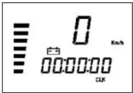
text_image
0 Km/h 00:00:00 CLKMINUTES:SECONDES 00:00.
text_image
=00:00 Km/h CLKMINUTES:SECONDES 00:00
text_image
TRP 0 Km/h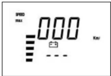
text_image
SPEED max 000 Km/Jtext_image
LAP 0 Km/hType Michelin - Trial Competition TT
Pression bar AV.0,8/AR. 0,6
flowchart
Electrical circuit diagram with labeled components and connections, including relays, switches, and meters1
SCHEMA ELECTRIQUE ALP 125
1) CLIGNOTANT AVANT DROIT (AMPOULE 12V-10W)
2| CONTACTEUR DE STOP AVANT
3| GROUPE COMMANDE DROITE
4| COUPE-CIRCUIT
5| BOUTON DU DÉMARREUR
natural_image
Interior view of a vehicle showing internal components with labeled parts (A and B), no readable text or symbols present.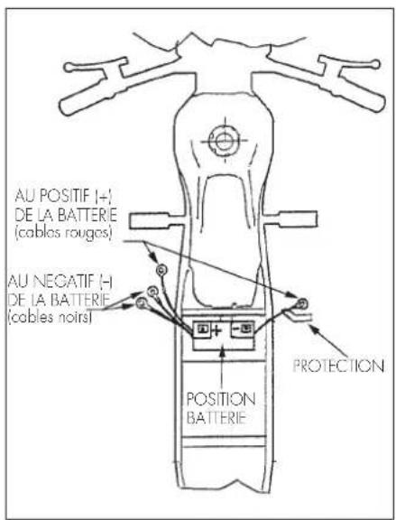
text_image
AU POSITIF (+) DE LA BATTERIE (cables rougos) AU NEGATIF (-) DE LA BATTERIE (cables noirs) POSITION BATTERIE PROTECTION1
BOÎTIER ÉLECTRONIQUE - TELÉRUPTEUR DU DÉMARREUR - RÉGULATEUR.
text_image
Labeled mechanical assembly diagram showing components A, B, C, D, and E with numbered annotationsnatural_image
Close-up of a car's head and engine compartment with labeled component (F), no visible text or symbols beyond the label.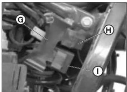
text_image
G H IF
TABLE DES MATIÈRES
CHAP. 2 UTILISATION DU VÉHICULE
natural_image
Close-up of a car engine bay with labeled component A, no readable text or symbols beyond label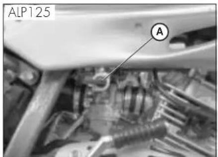
text_image
ALP125 A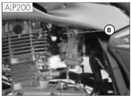
text_image
ALP200 B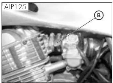
text_image
ALP125 BAvertissement:
natural_image
Mechanical assembly diagram showing a motor or gear component with labeled part A (no text or symbols beyond label)APPROVISIONNEMENT EN CARBURANT
text_image
Labeled diagram of a spacecraft or spacecraft with marked points E, C, and D indicating key components.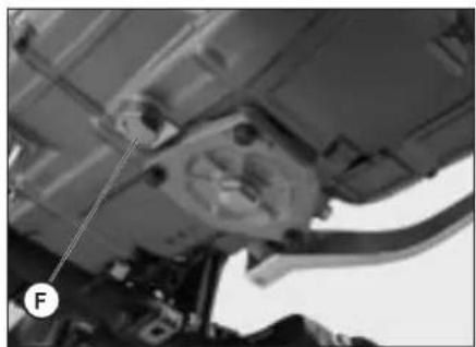
natural_image
Close-up of a mechanical assembly with visible components and a labeled point F (no text or symbols beyond label)HUILE MOTEUR ET FILTRE A HUILE ALP 200
Contrôle
natural_image
Close-up of a mechanical engine component with labeled part 'A' (no other text or symbols visible)Vidange
text_image
Labeled diagram of a spacecraft or spacecraft interior with marked points E, C, and DATTENTION:
natural_image
Close-up of a mechanical component with labeled parts (B), no readable text or symbols present.Attention:
natural_image
Close-up of a mechanical assembly with labeled component A (no visible text or symbols)TUYAU DE RÉCUPÉRATION DES FUMÉES
text_image
Labeled mechanical component diagram showing parts A, B, and C with visible wiring and adjustment knobsLIQUIDE DE FREIN, PURGE DU CIRCUIT
Frein avant
natural_image
Close-up of a bicycle wheel assembly with labeled parts A and B (no text or symbols beyond labels)text_image
Close-up of bicycle wheel components with labeled parts D and C, likely for safety or maintenance reference.F
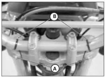
text_image
B AHUILE DE FOURCHE
Tubes droit
natural_image
Close-up of a motorcycle seat with a circular mark and label D pointing to the side (no text or symbols on the body)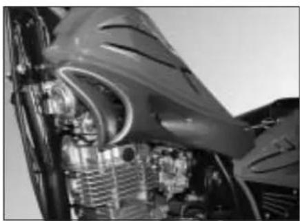
natural_image
Close-up of an aircraft engine bay with visible internal components and structural details (no text or symbols)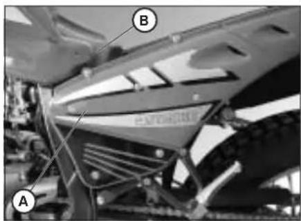
text_image
A B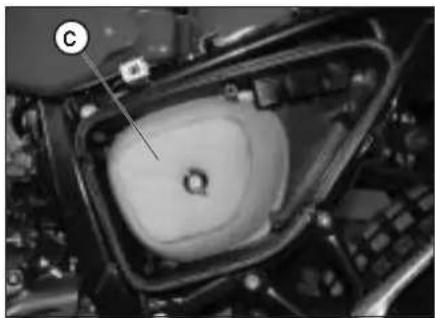
natural_image
Close-up of a mechanical component with a circular feature and labeled point C (no readable text or symbols)FILTRE À AIR
natural_image
Close-up of industrial machinery components with no visible text or symbols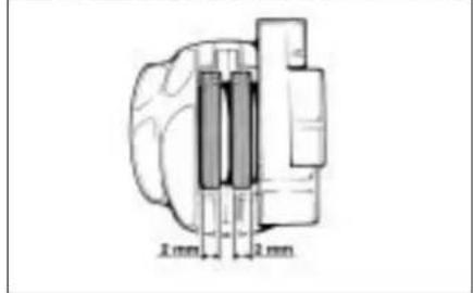
text_image
2 mm 2 mmFREIN AVANT
Contrôle
natural_image
Close-up of industrial machinery components (no visible text or symbols)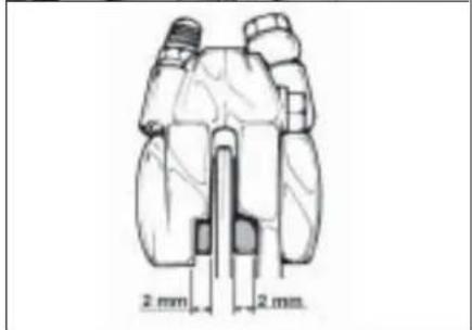
text_image
2 mm 2 mmFREIN ARRIÈRE
Contrôle
text_image
Technical diagram of a vehicle's front and rear engine compartment with labeled parts C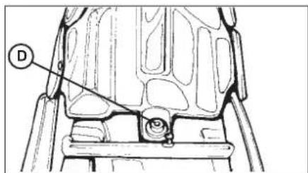
text_image
Technical diagram of a mechanical component with labeled part D and numbered parts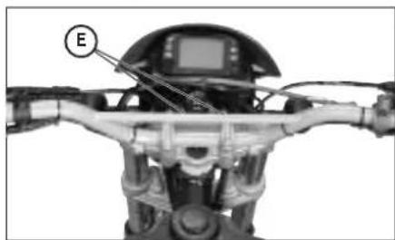
natural_image
Close-up of a robotic device with labeled component E, showing internal wiring and mechanical components (no readable text or symbols)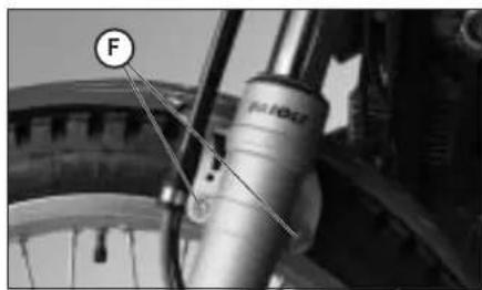
natural_image
Close-up of a bicycle wheel assembly with labeled component 'F' (no text or symbols beyond label)DÉPOSE DE LA CARROSSERIE
natural_image
Technical line drawing of a mechanical linkage assembly (no text or symbols)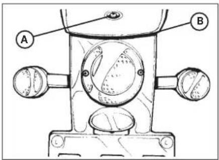
text_image
Technical diagram of a mechanical device with labeled parts A and B, showing internal components and mounting brackets.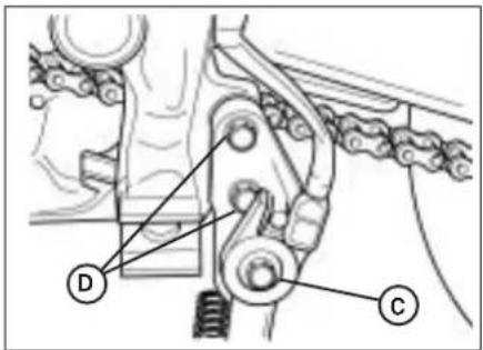
text_image
Technical diagram of a mechanical linkage system with labeled components D and C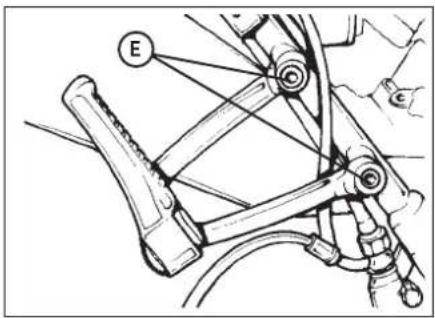
text_image
E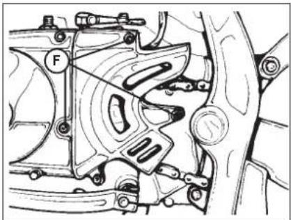
natural_image
Mechanical assembly diagram showing a motor or gear mechanism with no visible text or symbolsnatural_image
Close-up of a mechanical assembly with labeled component A (no readable text or symbols)natural_image
Close-up of a mechanical brake lever assembly with hoses and calipers (no visible text or symbols)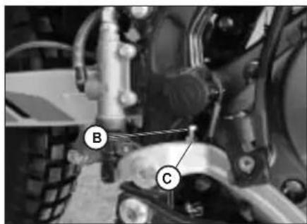
natural_image
Close-up of a mechanical assembly with labeled components (B and C), no readable text or symbols beyond labels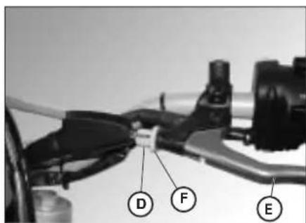
text_image
D F ERÉGLAGE DES FREINS
Frein avant
natural_image
Side view of a motorcycle wheel with visible mechanical components and a directional arrow (no text or symbols)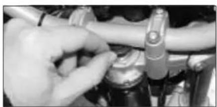
natural_image
Close-up of hands adjusting a mechanical component (no visible text or symbols)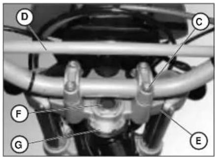
text_image
Labeled mechanical assembly diagram showing components D, C, F, G, and E with numbered partsF
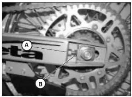
text_image
A B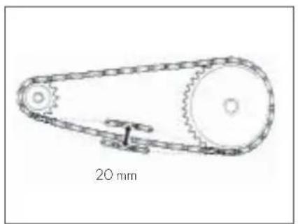
natural_image
Technical line drawing of a mechanical pulley system with 20 mm scale indicator (no text or symbols beyond label)TENSION DE LA CHAINE
natural_image
Close-up of mechanical components with no visible text or symbols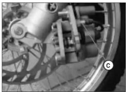
natural_image
Close-up of a mechanical assembly with visible gears and levers (no text or symbols)REMPLACEMENT DES PLAQUETTES DES FREINS
FREIN AVANT
natural_image
Close-up of a bicycle wheel and brake system with visible components (no text or symbols)natural_image
Close-up of a car wheel assembly with visible mechanical components (no text or symbols)CONTROLE USURE
natural_image
Close-up of hands operating a mechanical device with wires and components (no visible text or symbols)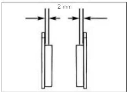
text_image
2 mmREMPLACEMENT DE L'AMPOULE DU PHARE AVANT
natural_image
Technical line drawing of a mechanical device with a circular component and cylindrical pins (no text or symbols)REMPLACEMENT DE L'AMPOULE DU PHARE ARRIÈRE
natural_image
Technical line drawing of a mechanical component with circular features and two side ports (no text or symbols)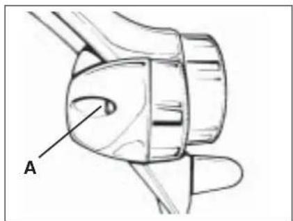
text_image
AREMPLACEMENT DES AMPOULES DES CLIGNOTANTS
natural_image
Close-up of mechanical components with visible wiring and a labeled section (A), no readable text or symbols present.MOTORNUMMER ALP 125
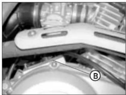
natural_image
Close-up of a mechanical device with labeled component B, no visible text or symbolsRAHMEN- UND MOTORNUMMER
natural_image
Close-up of mechanical components with a tool inserted, no visible text or symbolsAUSLIEFERUNG
natural_image
Line drawing of a mechanical tool setup with a cylindrical part, two rectangular parts, and a tool holder (no text or symbols)D
ZULADUNG
Typ: Trial competition TT
text_image
Labeled diagram of a motorcycle with numbered parts for identification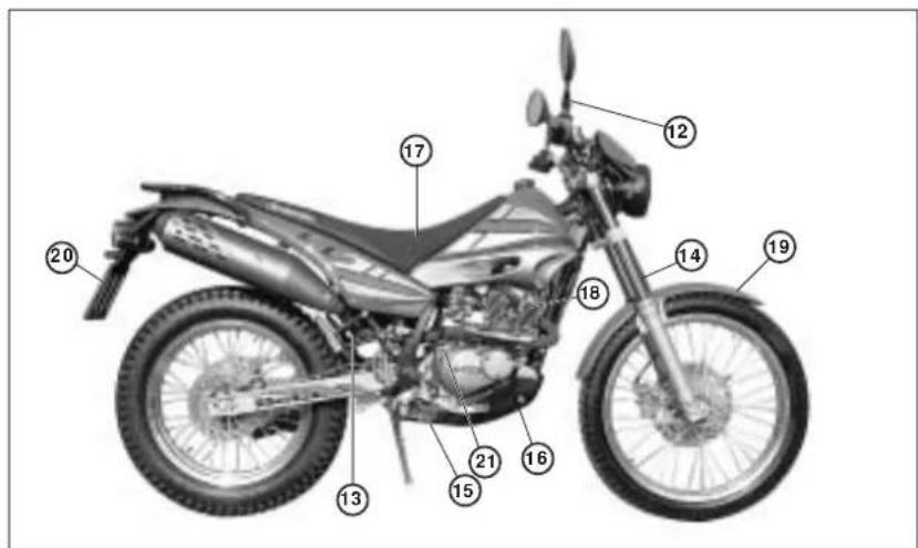
text_image
Labeled diagram of a motorcycle with numbered parts for identificationtext_image
Labeled diagram of a motorcycle body with numbered parts for identification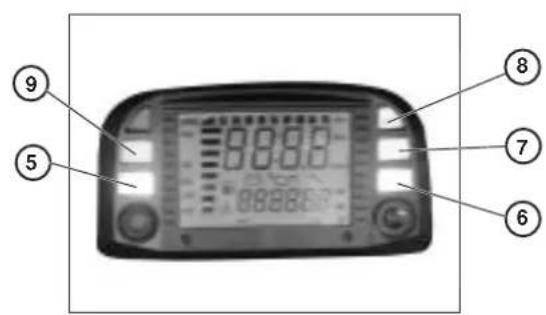
text_image
⑨ ⑤ 0000 0000 8888E ⑦ ⑥text_image
LAP 0 00:00:00 Km/htext_image
00:00 LAP 0 00 Km/htext_image
TRP 0 Km/h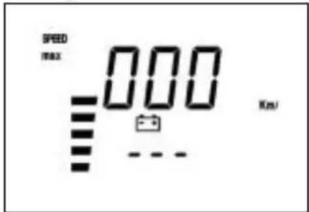
text_image
SPEED max 000 Km/stext_image
LAP 0 Km/hMichelin - Trial Competition TT
- links 350 cm ^4
Gabel.... NGK R CR7 HSA
flowchart
graph TD
    A["1"] --> B["2"]
    B --> C["3"]
    C --> D["4"]
    D --> E["5"]
    E --> F["6"]
    F --> G["7"]
    G --> H["8"]
    H --> I["9"]
    I --> J["10"]
    J --> K["11"]
    K --> L["12"]
    L --> M["13"]
    M --> N["14"]
    N --> O["15"]
    O --> P["16"]
    P --> Q["17"]
    Q --> R["18"]
    R --> S["19"]

    subgraph Inputs
        T["Vi, No"] --> U["Bi-Ne, Ci"]
        V["Bi-Gr"] --> W["Bi-Gr"]
        X["Bi-Ar"] --> Y["Bi-Ar"]
        Z["Bi-Ve"] --> AA["Bi-Vo"]
        AB["Bi-Na"] --> AC["Bi-Na"]
        AD["Bi-Ar"] --> AE["Bi-Ar"]
        AF["Bi-Ve"] --> AG["Bi-Vo"]
        AH["Bi-Na"] --> AI["Bi-Na"]
        AJ["Bi-Ar"] --> AK["Bi-Ar"]
        AL["Bi-Ve"] --> AM["Bi-Vo"]
        AN["Bi-Na"] --> AO["Bi-Na"]
        AP["Bi-Ar"] --> AQ["Bi-Ar"]
        AR["Bi-Ve"] --> AS["Bi-Vo"]
    end

    subgraph Outputs
        AT["48"] --> AU["Az/Ro, No, Bi/Bi"]
        AU --> AV["Az, Ro, Na, Bi/Bi"]
        AV --> AW["Az, Ro, Na, Bi/Bi"]
        AW --> AX["Az, Ro, Na, Bi/Bi"]
        AX --> AY["Az, Ro, Na, Bi/Bi"]
        AY --> AZ["Az, Ro, Na, Bi/Bi"]
        AZ --> BA["Az, Ro, Na, Bi/Bi"]
        BA --> BB["Az, Ro, Na, Bi/Bi"]
        BB --> BC["Az, Ro, Na, Bi/Bi"]
        BC --> BD["Az, Ro, Na, Bi/Bi"]
        BD --> BE["Az, Ro, Na, Bi/Bi"]
        BE --> BF["Az, Ro, Na, Bi/Bi"]
        BF --> BG["Az, Ro, Na, Bi/Bi"]
        BG --> BH["Az, Ro, Na, Bi/Bi"]
        BH --> BI["Az, Ro, Na, Bi/Bi"]
        BI --> BJ["Az, Ro, Na, Bi/Bi"]
        BJ --> BK["Az, Ro, Na, Bi/Bi"]
        BK --> BL["Az, Ro, Na, Bi/Bi"]
        BL --> BM["Az, Ro, Na, Bi/Bi"]
        BM --> BN["Az, Ro, Na, Bi/Bi"]
        BN --> BO["Az, Ro, Na, Bi/Bi"]
        BO --> BP["Az, Ro, Na, Bi/Bi"]
        BP --> BQ["Az, Ro, Na, Bi/Bi"]
        BQ --> BR["Az, Ro, Na, Bi/Bi"]
        BR --> BS["Az, Ro, Na, Bi/Bi"]
        BS --> BT["Az, Ro, Na, Bi/Bi"]
        BT --> BU["Az, Ro, Na, Bi/Bi"]
        BU --> BV["Az, Ro, Na, Bi/Bi"]
        BV --> BW["Az, Ro, Na, Bi/Bi"]
        BW --> BX["Az, Ro, Na, Bi/Bi"]
        BX --> BY["Az, Ro, Na, Bi/Bi"]
        BY --> BZ["Az, Ro, Na, Bi/Bi"]
        BZ --> CA["Az, Ro, Na, Bi/Bi"]
        CA --> CB["Az, Ro, Na, Bi/Bi"]
        CB --> CC["Az, Ro, Na, Bi/Bi"]
        CC --> CD["Az, Ro, Na, Bi/Bi"]
    end

    subgraph Outputs
        E1["2"] --> F1["Bi-Ne"]
        F1 --> G1["Bi-Gr"]
        G1 --> H1["Bi-Ar"]
        H1 --> I1["Bi-Ar"]
        I1 --> J1["Bi-Ve"]
        J1 --> K1["Na-Ma-Ne"]
        L1["2"] --> M1["Bi-Na"]
        M1 --> N1["Bi-Na"]
        O1["1"] --> P1["Bi-Na"]
        P1 --> Q1["Bi-Na"]
        R1["3"] --> S1["Bi-Na"]
        S1 --> T1["Bi-Na"]
        U1["4"] --> V1["Bi-Na"]
        V1 --> W1["Bi-Na"]
        X1["5"] --> Y1["Bi-Na"]
    end

    subgraph Outputs
        Z1["48"] --> AA2["Az/Ro, No, Bi/Bi"]
        AA2 --> AB2["Az/No/No/No/No/No/No/No/No/No/No/No/No/No/No/No/No/No/No/No/No/No/No/No/No/No/No/No/No/No/No/No/No/No/No/No/No/No/No/No/No/No/No/No/No/No/No/No/No/No/No/Nonumbered<br>    end<br>    <br>    subgraph Outputs<br>        AC1[47"] --> AD1["Az/Ro, No, Bi/Bi"]
        AD1 --> AE1["Az/No/No/No/No/No/No/No/No/No/No/No/No/No/No/No/No/No/No/No/No/No/No/No/No/No/No/No/No/No/No/No/No/No/No/No/No/No/No<br>    end<br>    <br>    subgraph Outputs<br>        AE2[44"] --> AF2["Az/Ro, No, Bi/Bi"]
        AF2 --> AG2["Az/No/No/No/No/No/No/No/No/No/No/No/No/No/No/No/No/No/No/No/No/No/No/No/No/No/<br>    end<br>    <br>    subgraph Outputs<br>        AG22[43"] --> AH2["Az/Ro, No, Bi/Bi"]
        AH2 --> AI2["Az/No/No/No/No/No/No/No/No/No/No/No/No/No/No/No/No/No/No/No/No/No<br>    end<br>    <br>    subgraph Outputs<br>        AI22[42"] --> AJ2["Az/Ro, No, Bi/Bi"]
        AJ2 --> AK2["Az/NO/NO/NO/NO/NO/NO/NO/NO/NO/NO/NO/NO/NO/NO/NO/NO<br>    end<br>    <br>    subgraph Outputs<br>        AJ22[41"] --> AK22["Az/Ro, No, Bi/Bi"]
        AK22 --> AL22["Az/NO/NO/NO/NO/NO/NO/NO/NO/NO/NO/NO/NO<nl><br>    end<br>    <br>    subgraph Outputs<br>        AM2[39"] --> AN2["Gir-Vo"]
        AN2 --> AO2["Nc-Nonumbered Nonumbered Nonumbered Nonumbered Nonumbered Nonumbered Nonumbered Nonumbered Nonumbered Nonumbered Nonumbered Nonumbered Nonumbered Nonumbered Nonumbered Nonumbered Nonumbered Nonumbered Nonumbered Nonumbered Nonumbered Nonumbered Nonumbered Nonumbered Nonumbered Nonumbered Nonumbered Nonumbered Nonumbered Nonumbered Nonumbered Nonumbered Nonumbered Nonumbered NonNumbered Nonumbered Nonumbered Nonumbered Nonumbered Nonumbered Nonumbered Nonumbered Nonumbered Nonumbered Nonumbered Nonumbered Nonumbered Nonumbered Nonumbered Nonumbered Nonumbered Nonumbered Nonumbered Nonumbered Nonumbered Nonumbered Nonumbered Nonumbered Nonumbered Nonumbered Nonumbered Nonumbered Nonumbered Nonumbered Nonumbered Nonumbered Nonumbered Nonumber of Nonumbered Nonumbered Nonumbered Nonumbered Nonumbered Nonumbered Nonumbered Nonumbered Nonumbered Nonumbered Nonumbered Nonumbered Nonumbered Nonumbered Nonumbered Nonumbered Nonumbered Nonumbered Nonumbered Nonumbered Nonumbered Nonumbered Nonumbered Nonumbered Nonumbered Nonumbered Nonumbered Nonumbered Nonumbered Nonumbered Nonumbered Nonumbered Nonumbered (30)<br>    end<br>    <br>    subgraph Outputs<br>        M2[35"] --> N2["Gir-Vo"]
        N2 --> O2["Gir-Vo"]
        O2 --> P2["Gir-Vo"]
        P2 --> Q2["Gir-Vo"]
        Q2 --> R2["Gir-Vo"]
        R2 --> S2["Gir-Vo"]
    end
natural_image
Interior view of a vehicle battery pack with labeled components (A and B), showing internal wiring and casing structure (no readable text or symbols beyond labels)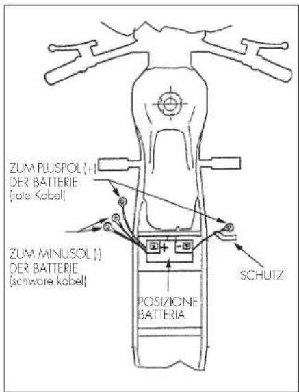
text_image
ZUM PLUSPOL (+) DER BATTERIE (role Kabel) ZUM MINUSOL (-) DER BATTERIE (schware kabel) POSIZIONE BATTERIA SCHUIZ1
ZÜNDBOX - ANLASSER-FERNRELAIS - GLEICHSTROMREGLER
text_image
Labeled mechanical assembly diagram showing components A, B, C, D, and E with visible wiring and componentsZÜNDSPULE
natural_image
Close-up of a car's head and side panel showing engine components (no visible text or symbols)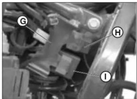
text_image
G H ID
INHALTSVERZEICHNIS
natural_image
Close-up of a car engine bay with labeled component 'A' and 'ALP 200' (no other text or symbols visible)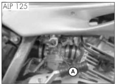
text_image
ALP 125 A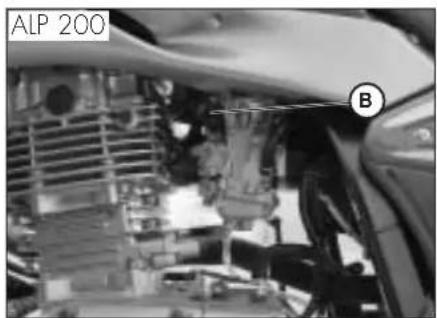
natural_image
Close-up of an automotive engine bay with visible components and a car silhouette (no text or symbols)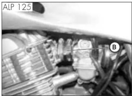
natural_image
Close-up of a car engine bay with visible components and labeled parts (ALP 125, B), no readable text or symbols beyond labels.Hinweis:
natural_image
Mechanical assembly diagram showing a component with labeled parts (A), no readable text or symbols present.TANKEN
text_image
Labeled diagram of a spacecraft or spacecraft interior with marked points E, C, and D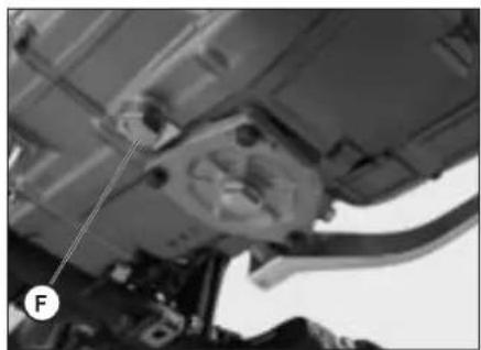
natural_image
Mechanical assembly diagram showing a component with labeled force F (no text or symbols beyond label)MOTORÖL UND ÖLFILTER ALP 200
Kontrolle
natural_image
Close-up of a mechanical engine component with labeled part 'A' (no other text or symbols visible)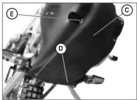
text_image
Labeled diagram of a spacecraft or spacecraft interior with marked points E, C, and D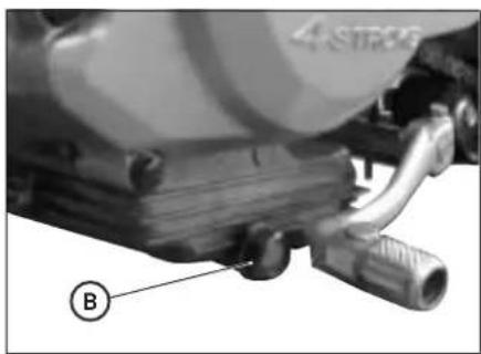
natural_image
Close-up of a mechanical component with labeled parts (B) and no visible text or symbolsD
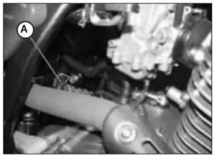
natural_image
Close-up of a mechanical assembly with labeled component A (no visible text or symbols)text_image
Labeled mechanical component diagram showing parts A, B, and C with visible wiring and adjustment knobsnatural_image
Close-up of a bicycle wheel assembly with labeled parts A and B (no text or symbols beyond labels)text_image
Close-up of bicycle wheel components with labeled parts D and C, likely for safety or maintenance reference.D
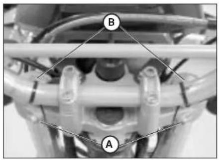
text_image
B AGABELÖL
Rechter Gabelschaft
natural_image
Close-up of a motorcycle seat with a circular mark and label D pointing to the side (no text or symbols on the body)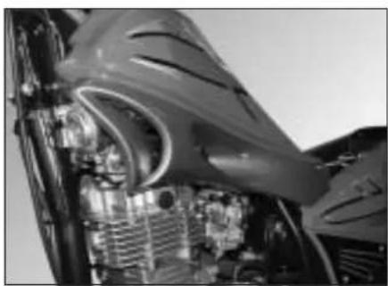
natural_image
Close-up of an aircraft engine bay with visible internal components and structural details (no text or symbols)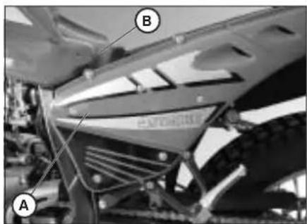
text_image
A B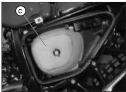
natural_image
Close-up of a mechanical component with a labeled section (C), showing internal structure and no readable text or symbols.LUFTFILTER
natural_image
Close-up of industrial machinery components (no visible text or symbols)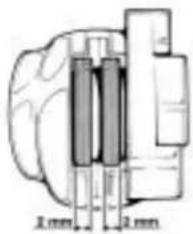
text_image
2mm 2mmVORDERRADBREMSE
Kontrolle
natural_image
Close-up of industrial machinery components (no visible text or symbols)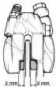
natural_image
Technical line drawing of a mechanical component with two cylindrical features and 2 mm dimension annotations (no text or symbols beyond measurement markers)HINTERRADBREMSE
Kontrolle
text_image
Technical diagram of a mechanical component with labeled parts C and C1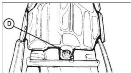
text_image
D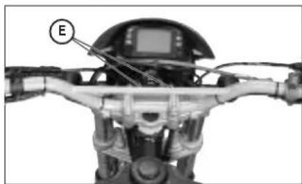
natural_image
Close-up of a robotic device with labeled component E, showing internal wiring and mechanical components (no readable text or symbols)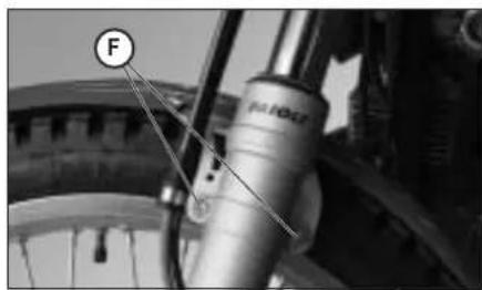
natural_image
Close-up of a bicycle wheel assembly with labeled component 'F' (no text or symbols beyond label)natural_image
Technical line drawing of a mechanical assembly with no visible text or symbols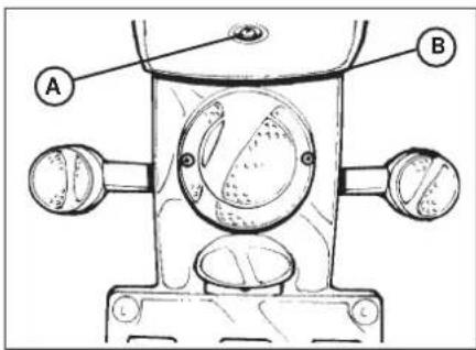
text_image
Technical diagram of a mechanical component with labeled parts A and B, showing internal components and mounting points.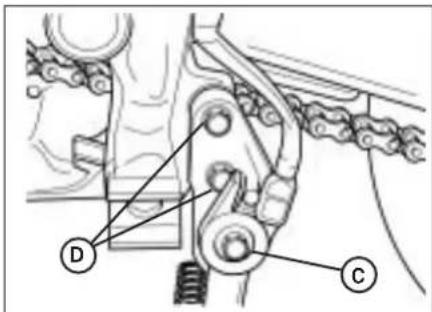
text_image
Technical diagram of a mechanical assembly with labeled components D and C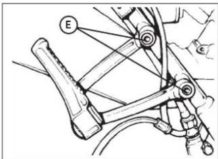
text_image
E
text_image
Fnatural_image
Close-up of an automotive engine bay with visible hoses and components (no text or symbols)natural_image
Close-up of a mechanical brake lever assembly with hoses and calipers (no visible text or symbols)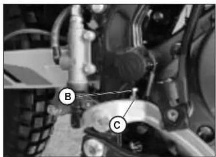
text_image
Mechanical assembly diagram with labeled components A and B, showing mechanical components and alignment indicators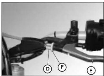
text_image
D F Enatural_image
Side view of a motorcycle's wheel and side-mounted blade (no text or symbols visible)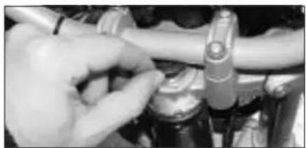
natural_image
Close-up of hands adjusting a mechanical component (no visible text or symbols)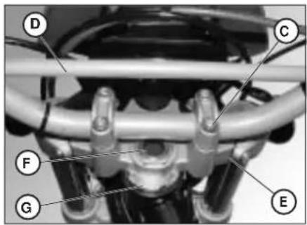
text_image
Labeled mechanical assembly diagram showing components D, C, F, G, and E with numbered partsD
SPANNEN DER KETTE
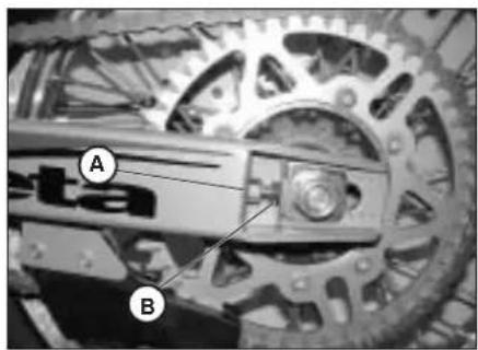
natural_image
Close-up of a mechanical gear assembly with labeled parts A and B (no readable text or symbols beyond labels)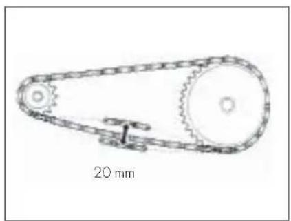
natural_image
Technical line drawing of a mechanical pulley system with 20 mm scale indicator (no text or symbols on the diagram itself)natural_image
Mechanical assembly diagram showing two labeled components A and B, with no visible text or symbols beyond labels.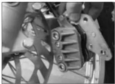
natural_image
Close-up of mechanical components with no visible text or symbols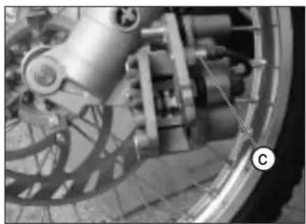
natural_image
Close-up of a mechanical assembly with visible gears and components (no text or symbols)AUSWECHSELN DER BREMSBELÄGE VORDERRADBREMSE
natural_image
Close-up of a bicycle wheel and brake system with visible components (no text or symbols)natural_image
Close-up of a car's wheel assembly and engine components (no visible text or symbols)VERSCHLEISSKONTROLLE
natural_image
Close-up of hands operating a mechanical device with wires and components (no visible text or symbols)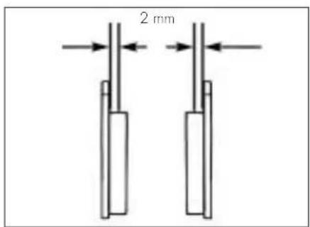
text_image
2 mmAUSWECHSELN DER SCHEINWERFER- LAMPEN
natural_image
Technical line drawing of a mechanical device with a circular component and bolts (no text or symbols)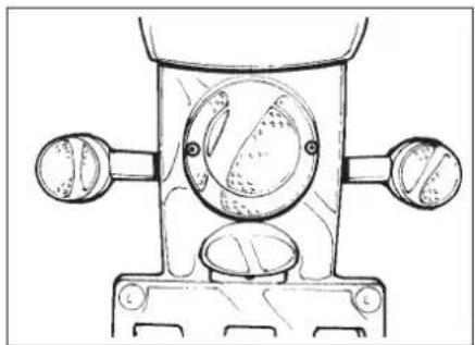
natural_image
Technical line drawing of a mechanical component with circular features and two side valves (no text or symbols)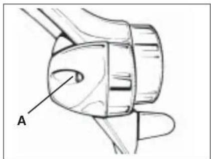
text_image
AAUSWECHSELN DER BLINKERLAMPEN
INFO RM ACIO NES GEN ERALS
IDENTIFICACION CHASIS
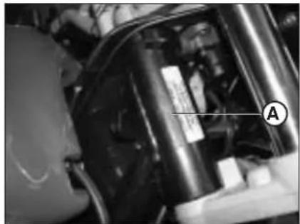
natural_image
Close-up of mechanical components with visible wiring and a labeled section (A), no readable text or symbols present.IDENTIFICACION MOTOR ALP125
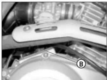
natural_image
Close-up of mechanical components with no visible text or symbolsnatural_image
Close-up of mechanical components with no visible text or symbolsSUMINISTRO
natural_image
Line drawing of a mechanical device with a cylindrical rod, two rectangular components, and a tool inserted into a housing (no text or symbols)E
CARGA
Tipo: Trial competition TT
text_image
Labeled diagram of a motorcycle with numbered parts for identification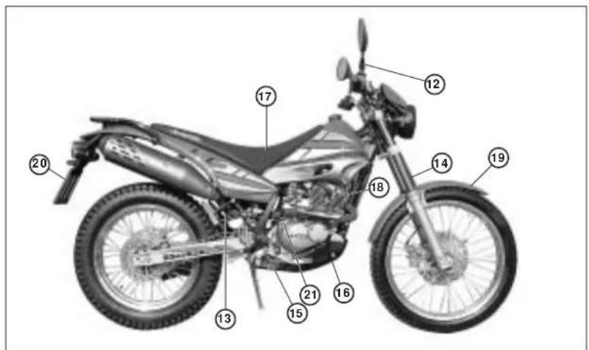
text_image
Labeled diagram of a motorcycle with numbered parts for identificationtext_image
Labeled diagram of a motorcycle body with numbered parts for identification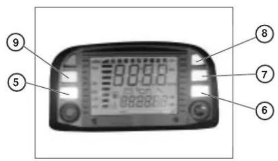
text_image
⑨ ⑤ 00.00 00.00 00.00 88.88.63 ⑧ ⑦ ⑥text_image
AXS 0 0.0 Km/htext_image
LAP 0 00:00:00 Km/hVisualiza:
text_image
00:00 Km/h LAP 0 00MINUTOS:SEGUNDOS 00:00,
text_image
TRP 0 Km/h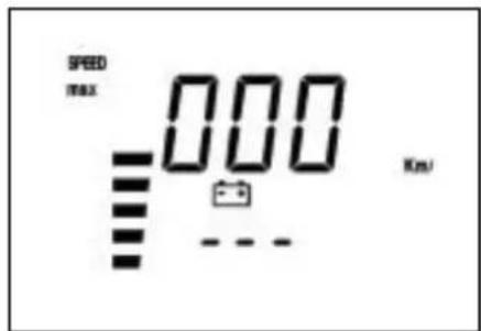
text_image
SPEED max 000 Km/Jtext_image
LAP 0 Km/hTipo....Michelin - Trial Competition TT
natural_image
Interior view of a device showing labeled components A and B, with no visible text or symbols beyond labels.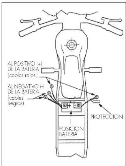
text_image
AL POSITIVO (+) DE LA BATERIA (cables rojos I) AL NEGATIVO (-) DE LA BATERIA (cables negros) POSICION BATERIA PROTECCION1
CENTRALITA - TELERRUPTOR DE ARRANQUE - REGULADOR
text_image
Labeled mechanical assembly diagram showing components A, B, C, D, and E with numbered annotationsBOBINA A.T.
natural_image
Close-up of a car's head and engine compartment with labeled component (F), no visible text or symbols beyond the label.FUSIBLE - INTERMITENCIA - RELE CABALLETE
natural_image
Close-up of a car engine bay with labeled component A (no readable text or symbols beyond label)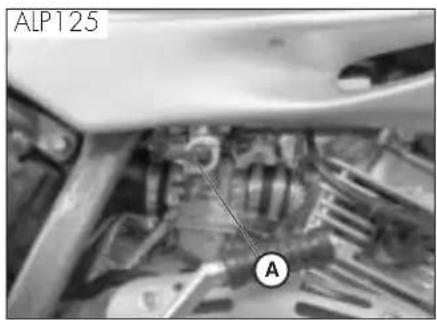
text_image
ALP125 A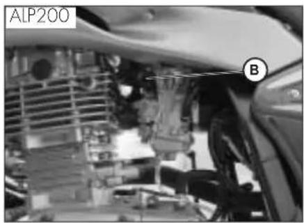
natural_image
Close-up of an automotive engine bay with visible components and a car silhouette (no text or symbols)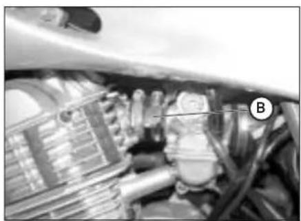
natural_image
Close-up of a car engine bay with visible hoses and components (no text or symbols)Advertencia:
natural_image
Mechanical assembly diagram showing a motor or gear component with labeled part A (no text or symbols beyond label)ABASTECIMIENTO DEL COMBUSTIBLE
text_image
Labeled diagram of a spacecraft or spacecraft interior with marked points E, C, and D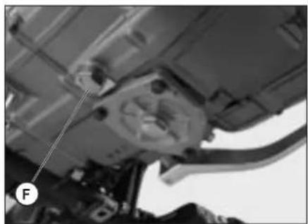
natural_image
Mechanical assembly diagram showing a component with labeled force F (no text or symbols beyond label)natural_image
Close-up of a mechanical engine component with labeled part 'A' (no other text or symbols visible)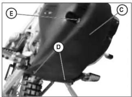
text_image
Labeled diagram of a spacecraft or spacecraft interior with marked points E, C, and D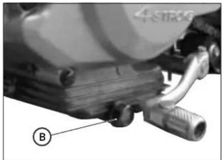
natural_image
Close-up of a mechanical component with labeled parts (B) and no visible text or symbols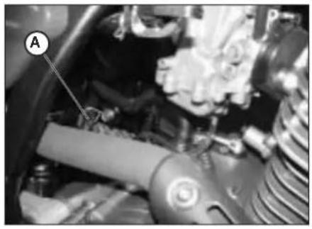
natural_image
Close-up of a mechanical assembly with labeled component A (no visible text or symbols)text_image
Labeled mechanical component diagram showing parts A, B, and C with visible wiring and adjustment knobsACEITE BOMBA FRENOS, ESPURGO FRENOS
Farol delantero
natural_image
Close-up of a bicycle wheel assembly with labeled parts A and B (no text or symbols beyond labels)Espurgo freno trasero
text_image
Close-up of bicycle wheel components with labeled parts D and C, likely for safety or maintenance reference.E
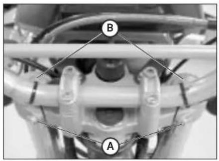
natural_image
Close-up of a mechanical assembly with labeled components A and B (no readable text or symbols beyond labels)ACEITE HORQUILLA
Barra derecha
CONTROLS Y MANUTENSION
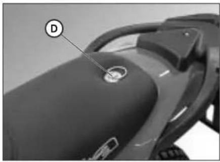
natural_image
Close-up of a motorcycle seat with a circular mark and label D pointing to the side (no text or symbols on the body)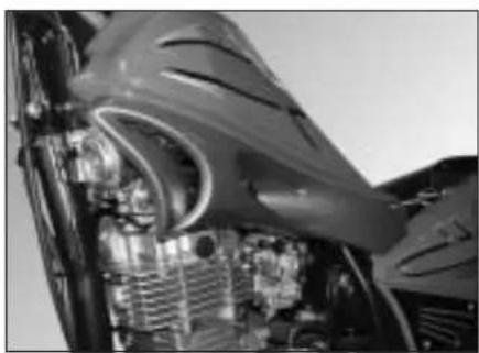
natural_image
Close-up of an aircraft engine bay with visible internal components and structural details (no text or symbols)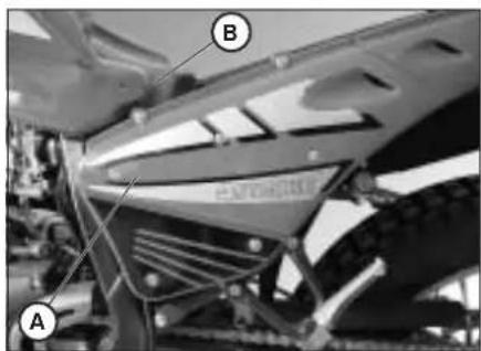
text_image
A B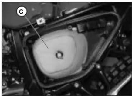
natural_image
Close-up of a mechanical component with a labeled section (C), showing internal structure and no readable text or symbols.FILTRO DE AIRE
natural_image
Close-up of industrial machinery components (no visible text or symbols)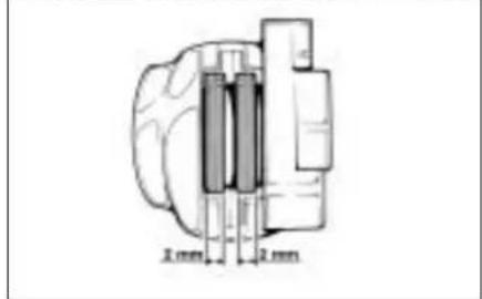
text_image
2 mm 2 mm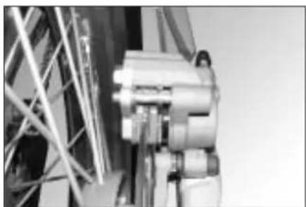
natural_image
Close-up of industrial machinery components (no visible text or symbols)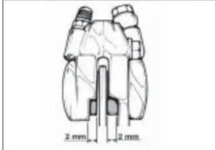
text_image
2 mm 2 mmFRENO DELANTERO
Comprobación
text_image
Technical diagram of a mechanical component with labeled parts C and C1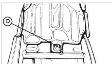
text_image
D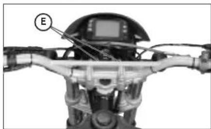
natural_image
Close-up of a robotic device with labeled component E, showing internal wiring and mechanical components (no readable text or symbols)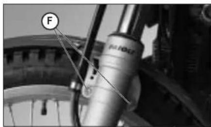
natural_image
Close-up of a bicycle wheel assembly with labeled component 'F' (no text or symbols beyond label)EXTRACCION DE LA CARROCERIA
natural_image
Technical line drawing of a mechanical linkage assembly (no text or symbols)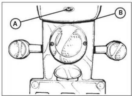
text_image
A B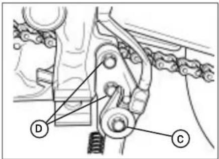
text_image
Technical diagram of a mechanical linkage system with labeled components D and C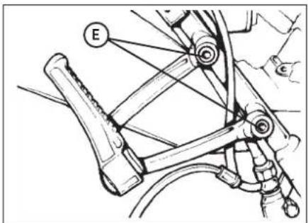
text_image
E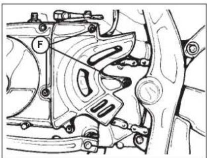
natural_image
Mechanical assembly diagram showing a motor or gear mechanism with no visible text or symbolsnatural_image
Close-up of a mechanical assembly with labeled component A (no readable text or symbols beyond label)natural_image
Close-up of a mechanical brake caliper assembly with hoses and levers (no visible text or symbols)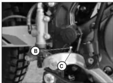
natural_image
Close-up of a tractor's wheel assembly with labeled parts B and C (no text or symbols beyond labels)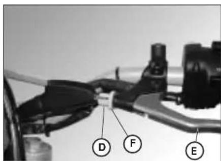
text_image
D F EREGUALACION FRENOS
Freno delantero
natural_image
Side view of a motorcycle's wheel and side-mounted blade (no text or symbols visible)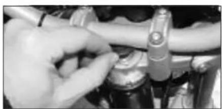
natural_image
Close-up of hands adjusting a mechanical component (no visible text or symbols)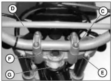
text_image
Labeled mechanical assembly diagram showing components D, C, F, G, and E with numbered partsE
natural_image
Close-up of a mechanical gear assembly with labeled parts A and B (no readable text or symbols beyond labels)natural_image
Close-up of mechanical components with no visible text or symbols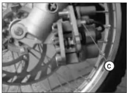
natural_image
Close-up of a bicycle brake system with visible components and a circular marker labeled 'C' (no text or symbols on the system itself)SUSTITUCION PASTILLAS FRENO DE- LANTERO
natural_image
Technical line drawing of a mechanical device with circular components and bolts (no text or symbols)natural_image
Technical line drawing of a mechanical component with circular features and two side ports (no text or symbols)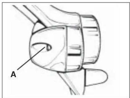
text_image
AEdition No. 3 / October 2006