GAGL30WSJG - Wardrobe Gladiator - Free user manual and instructions
Find the device manual for free GAGL30WSJG Gladiator in PDF.
User questions about GAGL30WSJG Gladiator
0 question about this device. Answer the ones you know or ask your own.
Ask a new question about this device
Download the instructions for your Wardrobe in PDF format for free! Find your manual GAGL30WSJG - Gladiator and take your electronic device back in hand. On this page are published all the documents necessary for the use of your device. GAGL30WSJG by Gladiator.
USER MANUAL GAGL30WSJG Gladiator
Models/Modeles/Modelos
GAGL30WSJG
GAGL30WSJW
TABLETTE MAX GEARLOFTTM
MAX GEARLOFT™ SHELF SAFETY......2
DIMENSIONS (TYPICAL INSTALL) 3
PARTS 3
INSTALLATION INSTRUCTIONS. 4
Max GearLoftTM Shelf Use
Requirements. 4
Unpack the Max GearLoftTM
Shelf Parts 4
Tools and Parts 4
ASSEMBLY INSTRUCTIONS 4
Install the Max GearLoft™ Shelf to the
Gladiator® Wall System. 5
Registering Your Product............6
WARRANTY 6
SECURITE DE LA TABLETTE MAX
GEARLOFTM 7
DIMENSIONS (INSTALLATION NORMALE)..8
PIECES 8
INSTRUCTIONS D'INSTALLATION 9
MAX GEARLOFT™ SHELF SAFETY
Your safety and the safety of others are very important.
We have provided many important safety messages in this manual and on your appliance. Always read and obey all safety messages.

This is the safety alert symbol.
This symbol alerts you to potential hazards that can kill or hurt you and others.
All safety messages will follow the safety alert symbol and either the word "DANGER" or "WARNING."
These words mean:
ADANGER
You can be killed or seriously injured if you don't immediately follow instructions.
WARNING
You can be killed or seriously injured if you don't follow instructions.
All safety messages will tell you what the potential hazard is, tell you how to reduce the chance of injury, and tell you what can happen if the instructions are not followed.
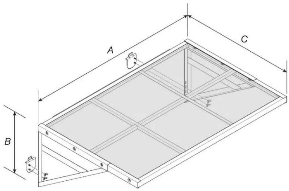
DIMENSIONS (TYPICAL INSTALL)
| MODEL | GAGL30WSJG GAGL30WSJW |
| A 45" (114 cm) | |
| B 16" (41 cm) | |
| C 30" (76 cm) |
PARTS
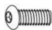

F3F1 F2
| Label Description Quantity | ||
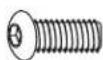
| F1 5/16" | Hex Head Bolt 6 | |
| F2 5/16" | Flange Nut 6 | |
| F3 Wing | Nut 4 | |
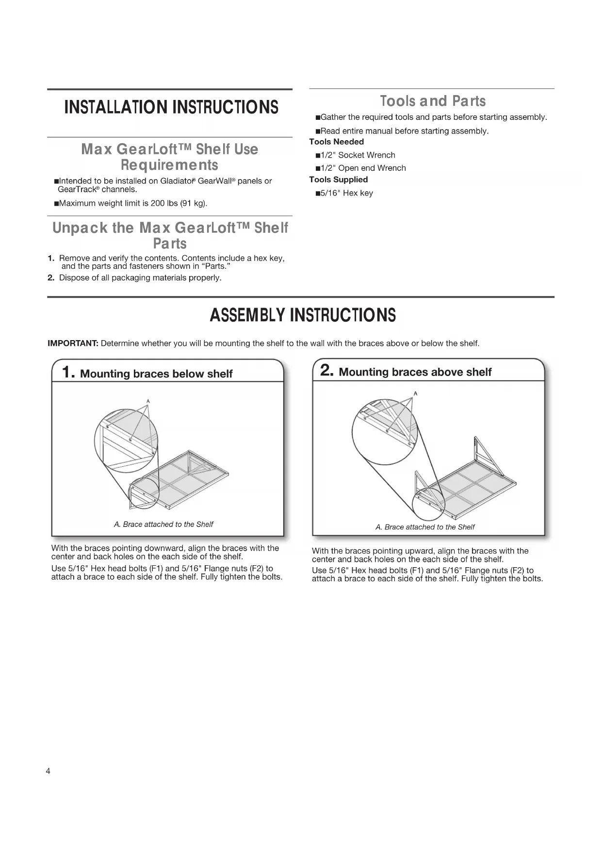
INSTALLATION INSTRUCTIONS
Max GearLoft™ Shelf Use Requirements
■Intended to be installed on Gladiator® GearWall® panels or GearTrack® channels.
Maximum weight limit is 200 lbs (91 kg).
Unpack the Max GearLoft™ Shelf Parts
- Remove and verify the contents. Contents include a hex key, and the parts and fasteners shown in "Parts."
- Dispose of all packaging materials properly.
Tools and Parts
Gather the required tools and parts before starting assembly.
Read entire manual before starting assembly.
Tools Needed
1/2" Socket Wrench
1/2" Open end Wrench
Tools Supplied
5/16" Hex key
ASSEMBLY INSTRUCTIONS
IMPORTANT: Determine whether you will be mounting the shelf to the wall with the braces above or below the shelf.
1. Mounting braces below shelf
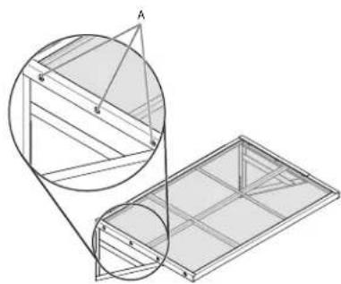
A. Brace attached to the Shelf
With the braces pointing downward, align the braces with the center and back holes on the each side of the shelf.
Use 5/16" Hex head bolts (F1) and 5/16" Flange nuts (F2) to attach a brace to each side of the shelf. Fully tighten the bolts.
2. Mounting braces above shelf
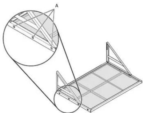
A. Brace attached to the Shelf
With the braces pointing upward, align the braces with the center and back holes on the each side of the shelf.
Use 5/16" Hex head bolts (F1) and 5/16" Flange nuts (F2) to attach a brace to each side of the shelf. Fully tighten the bolts.
INSTALL MAX GEARLOFT™ SHELF TO THE GLADIATOR WALL SYSTEM
1. Installing the GearTrack channel
Be sure the Gladiator® GearWall® panels or GearTrack® channels are installed with mounting screws in every slot and at every stud location with a maximum of 24" (60.96 cm) horizontally between screws.
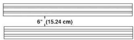
If installing the shelf on GearTrack® channel, you must use two channels installed 6" (15.24 cm) apart.
2. Sliding the brackets into the GearTrack® channel
Determine the shelf mounting location on Gladiator® GearWall® panels or GearTrack® channel.
Insert the brackets into the GearTrack® channel so that bracket rim extension fits behind the upper channel groove.
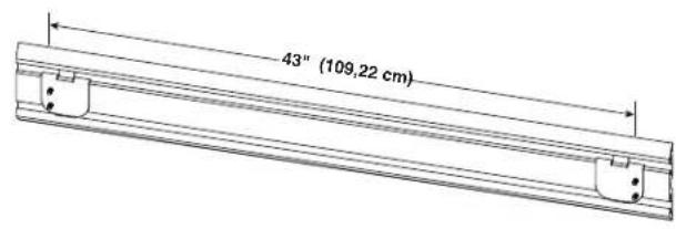
Slide the brackets in the GearTrack channel so that they are spaced 43^ (109.22 cm) apart as shown in above figure.
NOTE: Install bracket into the upper channel for installations with the braces above the shelf, or into the lower channel for installations with the braces below the shelf.
3. Installing Max GearLoft™ Shelf
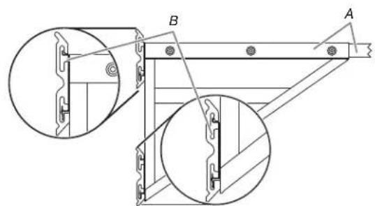
A. Brace attached to the Shelf B.Shelf attached to GearTrack
Engage the bracket that is welded to the back of the shelf into the wall slot by lifting up, pushing toward the wall and lowering the bracket rim into the slot as shown.
4. Fasten the braces to the brackets
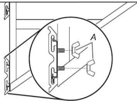
A. Wing nut
Make sure that the screws on the brackets go through the holes in the braces. Fasten the braces to the brackets using the wing nuts (F3).
NOTE: You may need to adjust the brackets to the right or left if the screws do not align with the holes.
Inspect the shelf from the side to ensure the bracket rims are fully engaged in the slots as shown.
Fully tighten the wing nuts (F3).
Registering Your Product
There are many benefits of registering your product. Find out more and register your product online at www.gladiatorgarageworks.com. In the USA, call 1-866-342-4089. Consumers in Canada can call 1-800-807-6777.
WARRANTY
For warranty information:
In the U.S.A. call 1-866-342-4089 or visit our website at
www.GliadiatorGW.com
In Canada call 1-800-807-6777 or visit our website at
www.gladiatorgarageworks.ca
SECURITE DE LA TABLETTE MAX GEARLOFTTM
DIMENSIONS (INSTALLATION NORMALE)

| MODELE | GAGL30WSJG GAGL30WSJW |
| A 45 po (11 | 4 cm) |
| B 16 po (4 | cm) |
| C 30 po (76 | cm) |
PIÉCES

F3F1 F2
www.gladiatorgarageworks.ca
SEGURIDAD DEL ESTANTE MAX GEARLOFT™
www.GliadiatorGW.com
www.gladiatorgarageworks.ca