GAJG36FDKSG - Wardrobe Gladiator - Free user manual and instructions
Find the device manual for free GAJG36FDKSG Gladiator in PDF.

User questions about GAJG36FDKSG Gladiator
0 question about this device. Answer the ones you know or ask your own.
Ask a new question about this device
Download the instructions for your Wardrobe in PDF format for free! Find your manual GAJG36FDKSG - Gladiator and take your electronic device back in hand. On this page are published all the documents necessary for the use of your device. GAJG36FDKSG by Gladiator.
USER MANUAL GAJG36FDKSG Gladiator
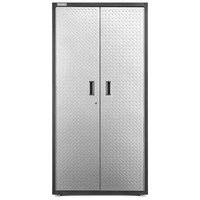
GAJG36FDYG - Hammered Granite/Silver Tread
GAJG36FDZW - Hammered White/Gray Slate
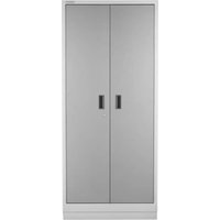
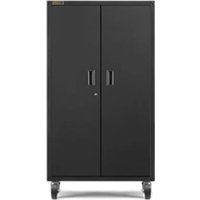
GAJG36FDKSG - Hammered Granite/Hammered Granite
GRANDE ARMOIRE (PREMIER JUMBO)
ASSEMBLY INSTRUCTIONS......3
Tools and Parts ....3
Cabinet Use Requirements......3
Unpack Cabinet Parts....3
Assemble Cabinet....3
Complete Assembly......6
INSTALLATION INSTRUCTIONS......7
ACCESSORIES......8
WARRANTY....9
SÉCURITÉ DE L'ARMOIRE .....10
PIÈCES ....10
INSTRUCTIONS D'ASSEMBLAGE...11
Outillage Et Pièces....11
www.gladiatorgarageworks.com
www.gladiatorgarageworks.ca
CABINET/ LOCKER SAFETY
Your safety and the safety of others are very important.
We have provided many important safety messages in this manual and on your appliance. Always read and obey all safety messages.

This is the safety alert symbol.
This symbol alerts you to potential hazards that can kill or hurt you and others.
All safety messages will follow the safety alert symbol and either the word "DANGER" or "WARNING."
These words mean:
DANGER
You can be killed or seriously injured if you don't immediately follow instructions.
WARNING
You can be killed or seriously injured if you don't follow instructions.
All safety messages will tell you what the potential hazard is, tell you how to reduce the chance of injury, and tell you what can happen if the instructions are not followed.
PARTS
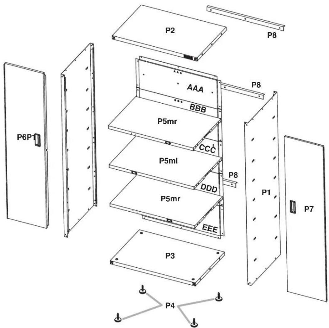
text_image
P2 P8 P6P1 AAA BBB P5mr CCC P5ml DDD P8 P1 P7 P5mr EEE P3 P4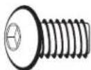
F1
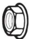
F2

F3
F7
F8
ASSEMBLY INSTRUCTIONS
Tools and Parts
Gather the required tools and parts before starting installation.
Tools Needed:
■ 1/2" Wrench
Level
■Phillips screwdriver
Tools Supplied:
■Hex key
■Key
Cabinet Use Requirements
■Intended for use in a garage.
■Maximum weight limit is 50 lbs (22.7 kg) for each shelf.
■Maximum weight limit is 300 lbs (136 kg) for the cabinet.
Unpack the Cabinet
- Remove and verify the contents. Contents include a hex key, a key, and the parts and fasteners shown in "Parts."
- Dispose of/recycle all packaging materials.
Assemble Cabinet
WARNING
Excessive Weight Hazard
Use two or more people to move, assemble or install cabinet.
Failure to do so can result in back or other injury.
IMPORTANT: Two people may be required to complete the assembly. As you assemble the cabinet, make sure the edges with the holes are facing up. If you are assembling the cabinet on the floor, fasten the eight front corner bolts, two at each corner, after you stand the cabinet upright.
- Assemble Cabinet

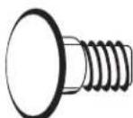
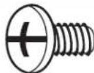
F1

F2
F1 5/16" hex-head bolt (28)
F2 5/16" flange nut (12)
text_image
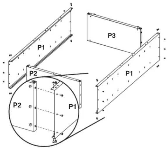
P1 P2 P3 P1 P2 P1Place side panel (P1) on a flat, firm surface so that the edge with the holes is facing up, as shown. Insert the cabinet top (P2) between the edges of side panel (P1).
NOTE: Make sure the edges with the holes are facing up.
Align the holes and attach the top (P2) to side panel (P1) using hex-head bolts (F1) and the three 5/16" flange nuts (F2), as shown. Do not tighten completely. Position the other side panel (P1) so that the top (P2) is between the edges of side panel (P1). Align the holes and attach the top (P2) to the side (P1) using hexhead bolts (F1) and the three 5/16" flange nuts (F2), as shown. Do not tighten completely. Insert the cabinet bottom (P3) between the edges of the side panels (P1).
NOTE: Make sure the edges with the holes are facing up.
Align the holes and attach the bottom (P3) to the sides (P1) using hex-head bolts (F1) and the three 5/16" flange nuts (F2). Do not tighten completely.
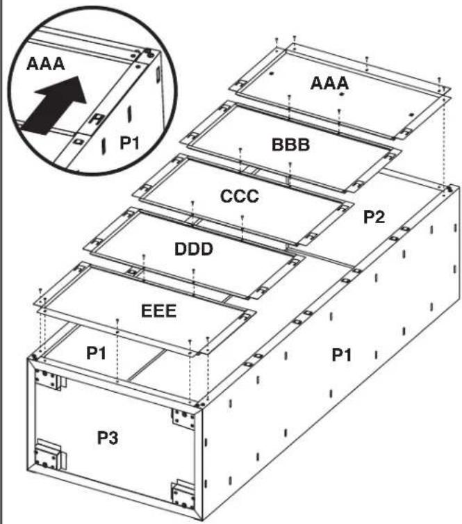
2. Attach Back Panels
F3c
F3c Phillips-head screw (34)
text_image
AAA P1 P1 AAA BBB CCC DDD EEE P2 P1 P1 P3IMPORTANT: Attach the back panels starting at the top of the cabinet with back panel (AAA) and working down to the cabinet bottom. Each back panel will overlap the panel below. Do not completely tighten the screws until all back panels are in place. Align back panel (AAA) with the holes in the cabinet top. Using Phillips-head screws (F3c), attach back panel (AAA) to the cabinet top and sides. Slide the top of back panel (BBB) under the bottom of back panel (AAA). Using Phillips-head screws, fasten back panel (BBB) to the cabinet sides. Repeat Step 2 for the remaining back panels ending with back panel (EEE). Using Phillips-head screws, attach each back panel to the panel below.
NOTE: Using Phillips-head screws, attach panel (EEE) to the cabinet bottom (P3).
Completely tighten all back panel screws starting with the sides and continuing with the top, middle and bottom. Using the hex key (provided), completely tighten all cabinet bolts and nuts.
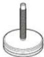
3. Install Leveling Legs (optional)
P4
Leveling feet (4)
text_image
P1 P4 EEE P3 AA. Leveling legs
IMPORTANT: If you are going to install the cabinet on Gladiator® GearWall® panels or GearTrack® channels, you do not need to install leveling legs.
Place the cabinet on its side. Screw a leveling leg (P4) into each of the four rivet nuts located at the corners of the cabinet, as shown. Stand the cabinet upright. If you have not already done so, fasten the two bolts at each front corner of the cabinet frame. Completely tighten all of the cabinet bolts and nuts.
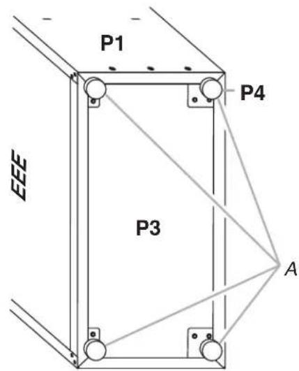
4a. Install Shelves
text_image
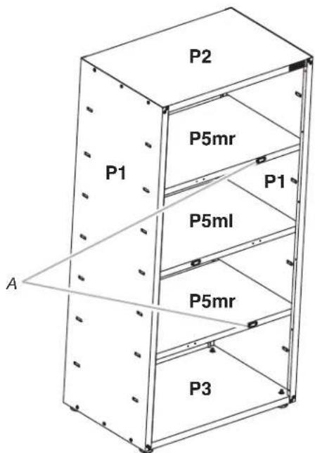
P2 P1 P1 P5ml A P3A. Middle pair of slots in cabinet side
IMPORTANT: Use the pair of slots located in the middle of the cabinet sides to install a center shelf (P5ml). The magnet should be on the left-hand side and facing out when installed, so that the door closure will make contact with the shelf, and the door will lock. The other two shelves may be installed where desired. The shelves are supported by the metal slots on the cabinet sides. Make sure that the shelf (P5ml) magnet is visible on the left-hand side and facing out, as shown.
Place a shelf (P5ml) so that the two tabs in the shelf ends are aligned with the pair of slots in the middle of the cabinet sides.
4b. Install Shelves
text_image
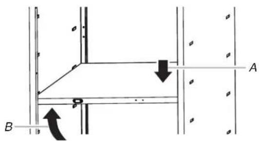
Technical diagram showing structural connection with labeled points A and B and directional arrows indicating movement or force.A. Push down
B. Lift up
text_image
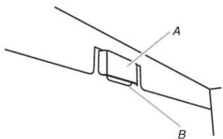
A BA. Cabinet slot
B. Shelf tab
Tilt the shelf so that one end is higher than the other, as shown. Insert the shelf into the cabinet so that the higher end is directly above the desired slots, and then push the shelf down into place behind the side slots. Raise the lower end so it is directly above the desired slots, and then push the shelf down.
NOTE: You may need to slightly bend the shelf tabs outward for the tabs to engage in the slots. Make sure the shelf tabs are in place behind all the slots, as shown.
4c. Install Shelves
text_image
P2 P5mr P1 P1 P5ml P5mr P3 AA. Magnet facing outward
Repeat steps 2 and 3 for the remaining two shelves (P5mr). The magnet for shelves (P5mr) is located on the right-hand side and facing out, as shown below.
NOTE: Make sure the magnet on the right side of each long shelf edge is facing out.
Adjust the Shelves
- Lift up on the underside of the shelf until the shelf tabs are free of the cabinet slots.
- Tilt the shelf up to reposition it within the cabinet or to remove it from the cabinet.
5. Install Doors
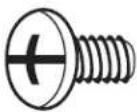
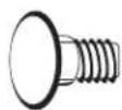
F3c
F3c Phillips-head screw (12)
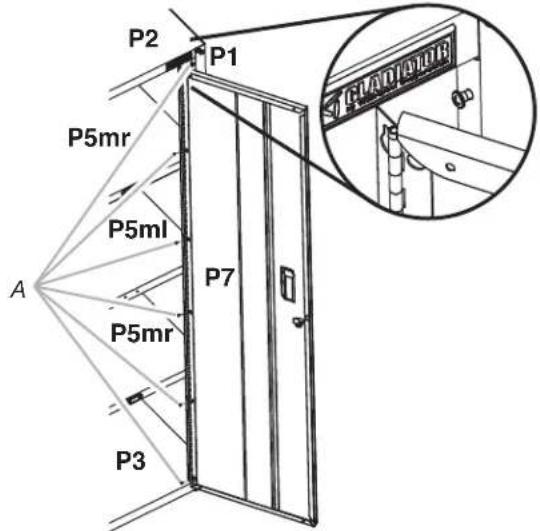
text_image
P2 P1 P5mr P5ml A P7 P5mr P3 CAD/ARURA. Phillips-head screws
IMPORTANT: The door with the lock assembly (P7) should be installed on the right-hand side of the cabinet. The door hinges are designed with keyhole slots at the top and bottom so the door will hang on the cabinet while you are fastening the screws. Start Phillips-head screws (F3c) in both the top and bottom holes on each side of the cabinet. Hang the right-hand side door (P7) from the top and bottom screws, and hand tighten. Insert the middle four screws through the door hinge into the cabinet and hand tighten. Repeat steps 2 and 3 to attach the left-hand door (P6). Align the doors and completely tighten the door screws.
Complete Assembly
- Make sure there is a bolt or screw in each hole of the cabinet frame.
- Move the cabinet to its final location.
- Place a level on an inside shelf, and if necessary, level the cabinet by adjusting the height of the leveling legs. Turn to the left to raise or to the right to lower the leveling leg.
- If the doors are not aligned, loosen all the screws attaching the door hinge to the cabinet.
- Adjust door to the desired height, and fully tighten the screws.
INSTALLATION INSTRUCTIONS
WARNING
Excessive Weight Hazard
Use two or more people to move, assemble or install cabinet.
Failure to do so can result in back or other injury.
1. Install GearWall ^® panels or GearTrack ^® channels
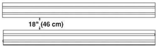
text_image
18" (46 cm)IMPORTANT: Gladiator brand Premier Jumbo cabinet is designed to be installed on Gladiator® GearWall® panels or GearTrack® channels. If GearTrack® channels will be used to support the Gladiator® Premier Jumbo GearBox cabinet, you must use three channels installed 18" (45.72 cm) apart. Be sure the GearWall® panels or GearTrack® channels are installed with mounting screws in every slot and at every stud location with a maximum of 24" (60.96 cm) horizontally between screws.
2a. Attach Mounting Brackets
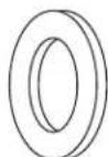

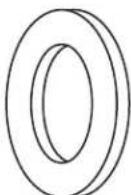
F8F7F2
F7 Carriage-head bolt (9) F8 Washer (9)
F2 5/16" flange nut (9)
text_image
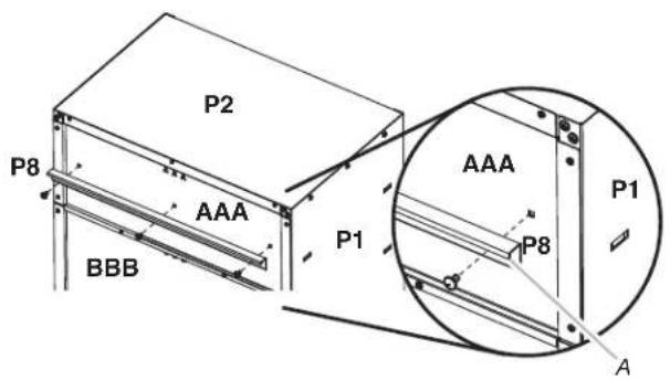
P2 P8 AAA BBB P1 AAA P8 P1 AA. Bracket rims pointing down
IMPORTANT: There are slots in back panels (AAA, CCC, and DDD) to attach the mounting brackets (P8).
With the mounting bracket rim pointing down, align the three bracket holes with the slots in back panel (AAA), as shown. Working from the back, insert carriage bolts (F7) through the bracket and into top back panel (AAA). Working from the cabinet interior, fasten each bolt with a washer (F8) and a flange nut (F2). Fully tighten the bolts.
2b. Attach Mounting Brackets
natural_image
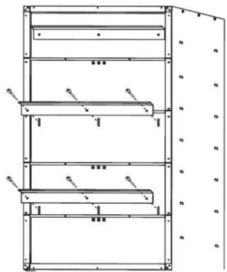
Technical line drawing of a multi-level industrial storage unit with no visible text or symbolsRepeat steps 1 and 2 to attach the center and bottom mounting brackets (P8) to the back of the cabinet.
NOTE: Hand tighten the nuts attaching the center and bottom brackets. These brackets will need to be adjusted to mount the cabinet on the wall.
- Mount the Cabinet to GearWall® Panels or GearTrack® Channel
text_image
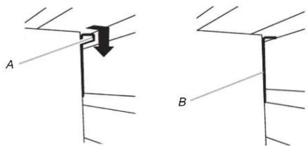
A BA. Bracket rim B. Mounting bracket fully engaged
NOTE: The three nuts on the center and bottom mounting brackets must be loose enough to allow the brackets to move in the slots.
Close the cabinet doors. Determine cabinet mounting location on GearWall® panels or GearTrack® channel. Using two or more people, engage the top bracket (P8) into the slots by lifting up, pushing toward the wall and lowering the bracket rims into the slots, as shown. Make sure the top bracket is fully engaged in the slots, as shown. Open the cabinet doors. From inside the cabinet, grasp the bolts in the center bracket and adjust the bracket until it aligns with the slot in the GearWall® panels or GearTrack® channels. Push the cabinet toward the wall and lower the center mounting bracket into the slots. Make sure the center bracket (P8) is fully engaged in the slot, as shown. Repeat for the bottom bracket (P8). Using a 1/2" wrench, fully tighten the nuts attaching the center and bottom brackets.
ACCESSORIES
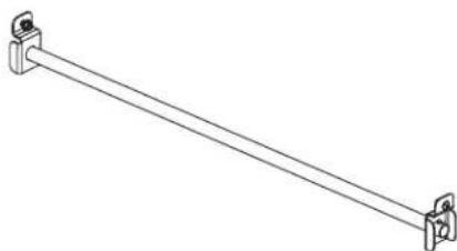
The Gladiator® GearRod accessory provides a hanging solution for heavy outdoor gear and other seasonal items, freeing up space in your household closets for everyday items. It attaches to any of the adjustable shelves or to the top of the cabinet. The Gladiator® GearRod holds up to 100 lbs of seasonal clothing and outdoor gear wear.
To order accessories, call 1-866-342-4089 and ask for the accessory part number listed below or contact your authorized Gladiator brand dealer. In Canada, call 1-800-807-6777.
GearRod Accessory
Order Part # GAAC36GRDSS
natural_image
Line drawing of a diagonal metal rod with two side clips (no text or symbols)WARRANTY
For warranty information:
In the U.S.A. call 1-866-342-4089 or visit our website at
www.gladiatorgarageworks.com
In Canada call 1-800-807-6777 or visit our website at
www.gladiatorgarageworks.ca
text_image
P2 P1 P1 P5ml A P3text_image
Technical diagram showing structural components with labeled points A and B and directional arrows indicating movement or force.text_image
18" (46 cm)natural_image
Technical line drawing of a multi-level mechanical or structural assembly with no visible text or symbolsA. Bracket rims pointing down
natural_image
Line drawing of a diagonal metal rod with two clamps at both ends (no text or symbols)GARANTIE
www.gladiatorgarageworks.com
www.gladiatorgarageworks.ca
text_image
P2 P1 P1 P5ml A P3text_image
Technical diagram showing structural connection with labeled points A and B and directional arrows indicating movement or force.text_image
18" (46 cm)natural_image
Technical line drawing of a multi-level metal shelving unit with no visible text or symbolsA. Bracket rims pointing down
natural_image
Line drawing of a diagonal metal rod with two mounting clips (no text or symbols)GARANTÍA
www.gladiatorgarageworks.com
www.gladiatorgarageworks.ca