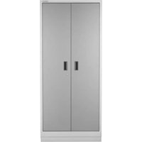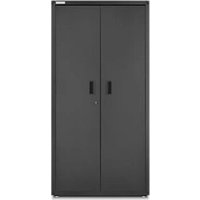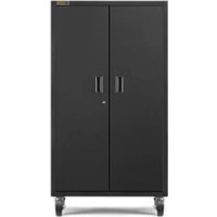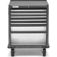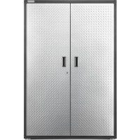
GAJG48KDYG - Wardrobe Gladiator - Free user manual and instructions
Find the device manual for free GAJG48KDYG Gladiator in PDF.



User questions about GAJG48KDYG Gladiator
0 question about this device. Answer the ones you know or ask your own.
Ask a new question about this device
Download the instructions for your Wardrobe in PDF format for free! Find your manual GAJG48KDYG - Gladiator and take your electronic device back in hand. On this page are published all the documents necessary for the use of your device. GAJG48KDYG by Gladiator.
USER MANUAL GAJG48KDYG Gladiator
GAJG48KDYG - Hammered Granite/Silver Tread
GAJG48KDKSG - Hammered Granite/Hammered Granite
GAJG48KDZW - Hammered White/Gray Slate
Modèle
Unpack the Cabinet. 4
Assemble Cabinet. 4
Complete the Assembly. 6
WEIGHT CAPACITY 7
ACCESSIONS. 7
WARRANTY 7
SECURITE DE L'ARMOIRE 8
PIECES 9
INSTRUCTIONS D'ASSEMBLAGE...10
Your safety and the safety of others are very important.
We have provided many important safety messages in this manual and on your appliance. Always read and obey all safety messages.

This is the safety alert symbol.
This symbol alerts you to potential hazards that can kill or hurt you and others.
All safety messages will follow the safety alert symbol and either the word "DANGER" or "WARNING."
These words mean:
DANGER
You can be killed or seriously injured if you don't immediately follow instructions.
WARNING
You can be killed or seriously injured if you don't follow instructions.
All safety messages will tell you what the potential hazard is, tell you how to reduce the chance of injury, and tell you what can happen if the instructions are not followed.
PARTS
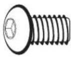
F1
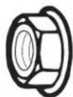
F2

F3

F5
ASSEMBLY INSTRUCTIONS
| F1 F2 F3 F5 5/16" Hex-head bolt (24) | Flange nut (8) Phillips-head screw (64) | Small flange nut (12) |
Tools and Parts
Gather the required tools before starting installation.
Tools Needed:
1/2"Wrench
Phillips screwdriver
3/8"Wrench
Level
Tool Supplied:
Hex key
Part Supplied:
■Key
Unpack the Cabinet
- Remove and verify the contents as shown in "Tools and Parts."
- Dispos of/recycle all packaging materials.
Assemble Cabinet
WARNING
Excessive Weight Hazard
Use two or more people to move, assemble or install cabinet.
Failure to do so can result in back or other injury.
IMPORTANT:
Two people may be required to complete the assembly.
As you assemble the cabinet, make sure the edges with the holes are facing up.
If you are assembling the cabinet on the floor, fasten the eight front corner bolts, two at each corner, after you stand the cabinet upright.
1.CabinetAssembly

F1
5/16" Hex-head bolt (24)

F2
Flange nut (8)
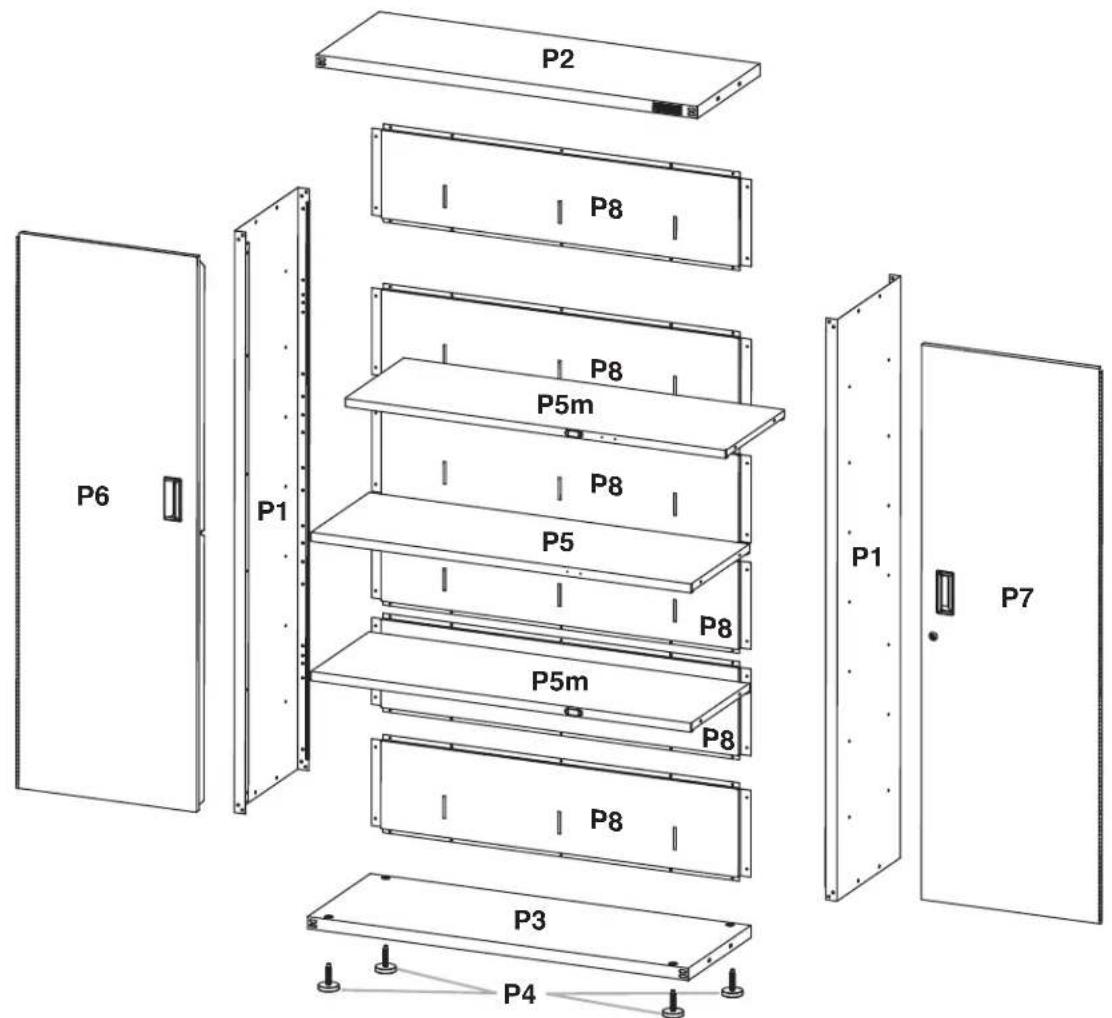
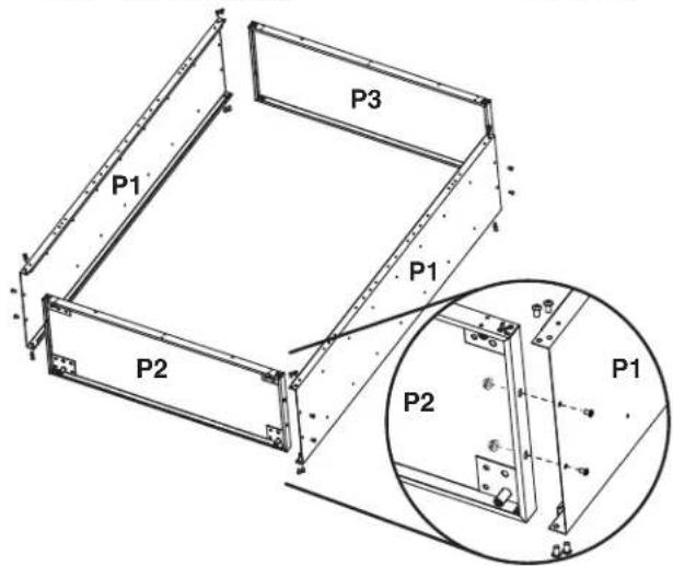
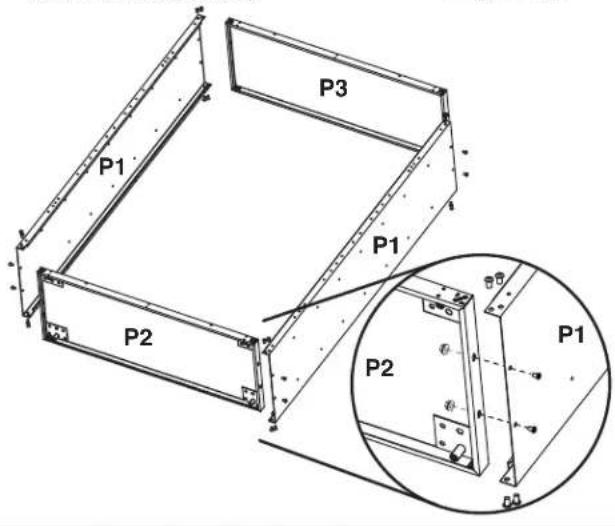
- Place side panel (P1) on a flat, firm surface so that the edge with the holes is facing up as shown.
- Insert the cabinet top (P2) between the edges of side panel (P1). NOTE: Make sure the edges with the holes are facing up.
- Align the holes and attach the top (P2) to side panel (P1) using six hex-head bolts (F1) and two 5/16" flange nuts (F2) as shown. Do not tighten completely.
- Position the other side panel (P1) so that the top (P2) is between the edges of side panel (P1).
- Align the holes and attach the top (P2) to the side (P1) using six hex-head bolts (F1) and two 5/16'' flange nuts (F2) as shown. Do not tighten completely.
- Insert the cabinet bottom (P3) between the edges of the side panels (P1). NOTE: Make sure the edges with the holes are facing up.
- Align the holes and attach the bottom (P3) to the sides (P1) using six hex-head bolts (F1) and two 5/16'' flange nuts (F2) for each side as shown. Do not tighten completely.
2. Attach Back Panel
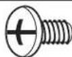
F3

Phillips-head screw (40)
IMPORTANT:
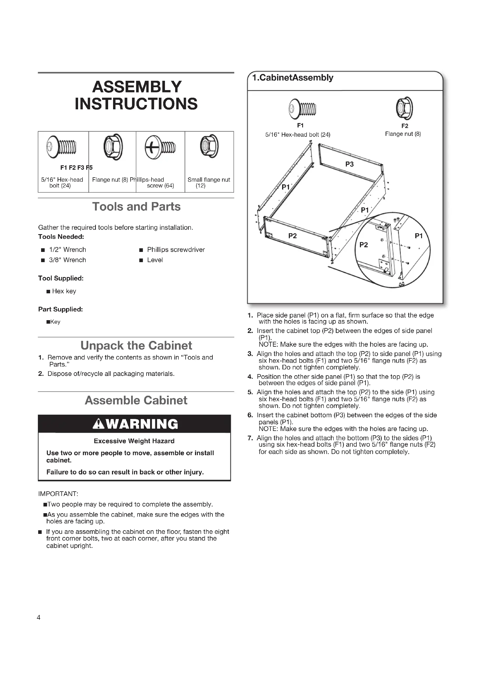
- Attach the back panels (P8) starting at the top of the cabinet and working down to the cabinet bottom. Each consecutive back panel will overlap the panel above.
■Do not completely tighten the screws until all back panels are in place.
The back panels, top and bottom, may have additional holes that are not used. - Align the first back panel (P8) with the holes in the cabinet top. Using phillips-head screws (F3), attach the panel (P8) to the cabinet top and sides.
- Overlap the bottom of the first back panel (P8) with the top of the second back panel (P8) as shown. Using phillips-head screws (F3), fasten back panel (P8) to the cabinet sides.
- Repeat Step 2 to attach the four remaining back panels to the cabinet sides.
- Using two phillips-head screws, attach each back panel to the panel below. NOTE: Using three phillips-head screws (F3), attach the last back panel (P8) to the cabinet bottom (P3).
- Completely tighten all back panel screws starting with the sides and continuing with the top, middle and bottom.
- Using the hex key (provided), completely tighten all 24 cabinet bolts and nuts.
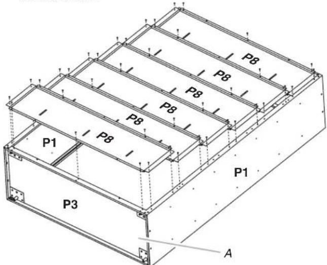
A. Cabinet Bottom
3. Install Leveling Feet
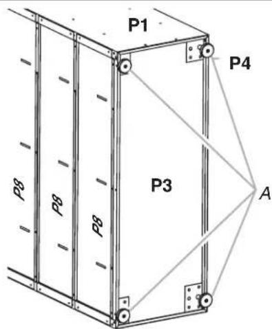
A. Leveling feet
To install leveling feet:
- Place the cabinet on its side.
- Screw a leveling foot (P4) into each of the four rivet nuts located at the corners of the cabinet as shown.
- Stand the cabinet upright.
- If you have not already done so, fasten the two bolts at each front corner, of the cabinet frame. Completely tighten all the cabinet bolts and nuts.
4.InstallShelves

F3 F5
Phillips-head screw (12)

Small flange nut (12)
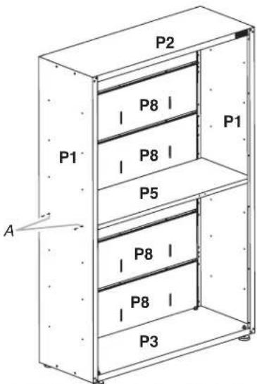
A.Middle pair of holes in cabinet side
IMPORTANT: Use the pair of holes located in the middle of the cabinet sides to install a center shelf without the magnet (P5), so the doors will lock. The other two shelves with magnet (P5m) may be installed where desired.
- Place a shelf (P5) so that the holes in the ends are aligned with the pair of holes in the middle of the cabinet sides. NOTE: Make sure the holes in the long edge of the shelf are facing out.
- Using two phillips-head screws (F3) and two flange nuts (F5) per side, fasten the shelf (P5) to the sides (P1).
- Determine where you want to place the other two shelves (P5m). Align the holes in the shelf ends with the holes in the cabinet NOTE: Make sure the magnets on the long edge of the shelf are facing the cabinet front.
- Using two phillips-head screws (F3) and two flange nuts (F5) per side, fasten the shelves (P5m) to the cabinet sides (P1). Completely tighten the nuts.
5.InstallDoors
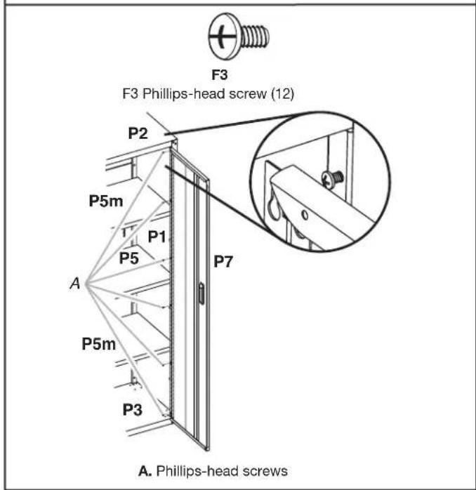
IMPORTANT:
The door with the lock assembly (P7) should be installed on the right-hand side of the cabinet.
The door hinges are designed with keyhole slots at the top and bottom so the door will hang on the cabinet while you are fastening the screws.
- Start phillips-head screws (F3) in both the top and bottom holes on each side of the cabinet.
- Hang the right-hand side door (P7) from the top and bottom screws, and hand tighten.
- Insert the middle four phillips-head screws (F3) through the door hinge into the cabinet and hand tighten.
- Repeat steps 2 and 3 to attach the left-hand door (P6).
- Align the doors and completely tighten the screws.
Complete the Assembly
- Make sure there is a bolt or screw in each hole of the cabinet frame. NOTE: The back panels, top and bottom, may have additional holes that are not used.
- Move the cabinet to its final location.
- Place a level on an inside shelf, and if necessary, level the cabinet by adjusting the height of the leveling feet. Turn to the left to raise or to the right to lower the leveling foot.
- If the doors are not aligned, loosen all the screws attaching the door hinge to the cabinet. Adjust door to the desired height, and fully tighten the screws.
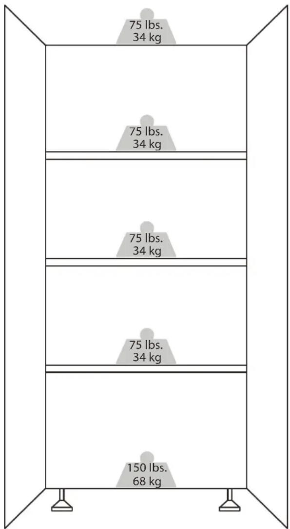
WEIGHT CAPACITY
ACCESSORIES
To order accessories, call 1-866-342-4089 and ask for the accessory part number listed below or contact your authorized Gladiator®
GarageWorks dealer. In Canada, call 1-800-807-6777. Mounting Bracket Kit - Allows the cabinet to be mounted on
Gliadiator® Garageworks GearWall® panels or GearTrack® channels.
Order Part # GABK362PSS
WARRANTY
For warranty information:
In the U.S.A. call 1-866-342-4089 or visit our website at
www.gladiatorgarageworks.com
In Canada call 1-800-807-6777 or visit our website at
www.gladiatorgarageworks.ca
SECURITE DE L'ARMOIRE
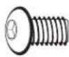
F1
5/16" Hex-head bolt (24)

F2
Flange nut (8)
www.gladiatorgarageworks.com
www.gladiatorgarageworks.ca
www.gladiatorgarageworks.com
www.gladiatorgarageworks.ca