
Barett - Basket Klarstein - Free user manual and instructions
Find the device manual for free Barett Klarstein in PDF.
| Product type | Range hood (island) |
| Brand | Klarstein |
| Model | Barett |
| Power supply | 220-240 V ~ 50/60 Hz |
| Number of speeds | 3 (low, medium, high) |
| Timer | Yes, adjustable from 1 to 60 minutes |
| Lighting | LED 1 W, DC 4 V |
| Remote control | Yes |
| Grease filter | Hand washable fabric |
| Charcoal filter | Optional, replace every 3 to 6 months |
| Noise level (min / max) | 62 dB / 72 dB |
| Annual energy consumption | 57.9 kWh/year |
| Energy efficiency class | B |
| Airflow (min / max) | 317.8 m³/h / 537.8 m³/h |
| Installation distance above the hob | 65 to 75 cm |
| Material | Stainless steel |
| Exhaust mode | Extraction or recirculation |
| Supported ceiling weight | Minimum 120 kg |
| Article numbers | 10032301, 10032302, 10032303, 10035165 |
Frequently Asked Questions - Barett Klarstein
User questions about Barett Klarstein
0 question about this device. Answer the ones you know or ask your own.
Ask a new question about this device
Download the instructions for your Basket in PDF format for free! Find your manual Barett - Klarstein and take your electronic device back in hand. On this page are published all the documents necessary for the use of your device. Barett by Klarstein.
USER MANUAL Barett Klarstein
Member of Berlin Brands Group
Handwerkerstr. 11
15366 Dahlwitz-Hoppegarten
Deutschland
Berlin Brands Group UK Ltd
PO Box 1145
Oxford,OX1 9UW
United Kingdom
Dear customer,
Congratulations on the purchase of your device. Please read the following instructions carefully and follow them to prevent potential damage. We accept no liability for damage caused by disregarding the instructions and improper use. Please scan the QR code to access the latest operating instructions and further information about the product.

CONTENTS
Safety instructions 26
Installation (external ventilation) 28
Notes for the installation of the exhaust air pipe 33
Control panel and function keys 34
Remote control and features 34
Troubleshooting 36
Cleaning and care 36
Product data sheet 40
Notes on environmental protection 42
Disposal considerations 43
Manufacturer & importer (UK) 43
TECHNICAL INFORMATION
| Item number | 10032301, 10032302, 10032303, 10035165 |
| Power supply 220-240 V ~ 50/60 Hz |
SAFETY INSTRUCTIONS
- Read all instructions carefully before use and keep the user manual in a safe place for future reference.
- The installation work may only be carried out by an electrician or a qualified person. Before using the cooker hood, make sure that the voltage (V) and frequency (Hz) indicated on the cooker hood correspond to the voltage and frequency of the power supply in your household.
We accept no liability for damage caused by improper use or installation.
Children under 8 years of age must not use the cooker hood. - The appliance is intended for use in the home and similar environments only. It is not intended for commercial use.
- Clean the appliance and the filter regularly to keep the appliance working efficiently.
Always disconnect the power plug from the socket before cleaning. - Clean the appliance exactly as indicated in the operating instructions.
- Do not use an open fire under the extractor hood.
- If the unit is not functioning normally, contact the manufacturer or a specialist company.
- Children from the age of 8 years and mentally, sensory and physically impaired persons may only use the device if they have been informed in detail about the functions and safety precautions by a supervisor responsible for them beforehand and understand the associated risks.
- If the power cord is damaged, it must be replaced by the manufacturer, an authorised specialist company or a similarly qualified person.
- If the cooker hood is used with cookers that burn gas or other fuels, there must be adequate ventilation in the room.
- Do not flambé under the extractor hood.
- Caution: The surface of the unit may become hot during operation.
Important instructions for installation
- The air must not be discharged into a flue used for extracting flue gases from gas or other fuels (does not apply to appliances that only return the air to the room).
- Observe all regional regulations for the installation of ventilation systems.

WARNING
Danger of poisoning from recirculated exhaust gases! Do not operate the appliance in extract air mode if it is operated together with a room air-dependent fi replace and suffcient air circulation is not guaranteed.
Room air-dependent fi replaces such as gas, oil, wood or coal heaters, boilers or instantaneous water heaters draw the air from the room and lead it outdoors through an exhaust pipe or chimney. In extract air mode, air is extracted from the kitchen and neighbouring rooms. Without sufficient supply air, negative pressure is created. Toxic gases from the chimney or exhaust pipe can be sucked back into the living rooms.
- Make sure that sufficient fresh air supply is guaranteed and that the air can circulate.
- A supply air/exhaust air wall box is not sufficient to ensure compliance with the limit value.
Safe operation is only possible if the negative pressure at the location of the fi replaces does not exceed 4 Pa (0.04 mbar). This can be achieved if the air required for combustion can flow in through non-closable openings in doors and windows in conjunction with a supply air / exhaust air wall box. In any case, have a master chimney sweep advise you and assess the entire ventilation system of the house. If necessary, they can tell you the necessary measure for ventilation.
If the cooker hood is used exclusively in recirculation mode, operation is possible without restriction.
Important note on dismantling the unit
- Disassembly is the same as installation/assembly in reverse order.
- Have a second person help you during disassembly to avoid injury.
INSTALLATION (EXTERNAL VENTILATION)
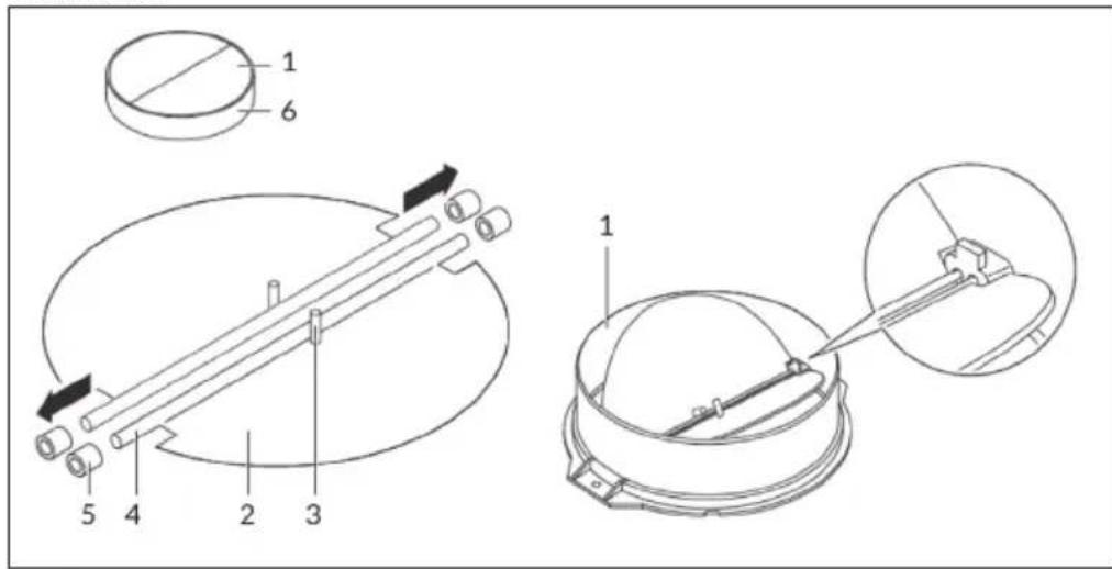
Mounting the V flap
If the cooker bonnet does not have a pre-assembled V-flap, install the parts as follows:
1 Install the first half (2) into the housing (6).
2 The pin (3) should be facing upwards.
3 The axle (4) is inserted into the holes (5) on the housing.
4 Repeat all the steps for the second half of the flap.
Installation
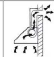
If you have an air outlet to the outside, the cooker bonnet can be connected via an extraction duct (enamel, aluminium, flexible pipe or non-combustible material with an internal diameter of 150mm ) as shown on the right.
-
Before fixing the appliance, switch it off.
-
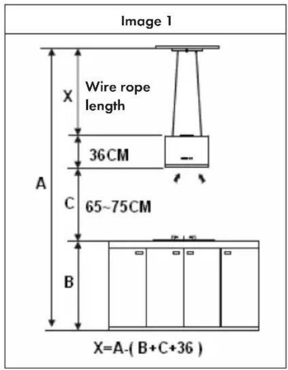
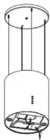
The cooker bonnet should be positioned at a distance of 65 - 75cm to the cooking surface in order to ensure its optimal efficiency. See image 1.
-
The ceiling must be able to support a weight of at least 120kg and the thickness of the ceiling must be ≥ 30mm .
-
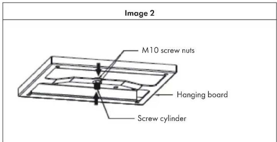
Attach the screw cylinder to the hanging board and use two M10 screw nuts to secure the screw cylinder to the hanging board from above and below. The upper end of the screw cylinder overlaps the nut by 1 mm (see image 2).
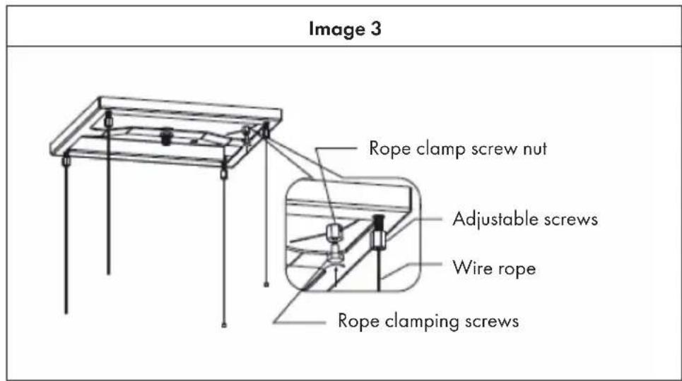
- Attach the 4 adjustable screws to the hanging board, turn them to the right length and not too tight. The height of the 4 screws is basically the same. Pass the 4 wire ropes through the 4 adjustable screws, calculate the length of the wire rope according to image 1 and mark the length on the rope. Use the 4 rope clamping screws + nuts to fix the 4 ropes at the marked points. Make sure that the 4 ropes are of equal length (see image 3).
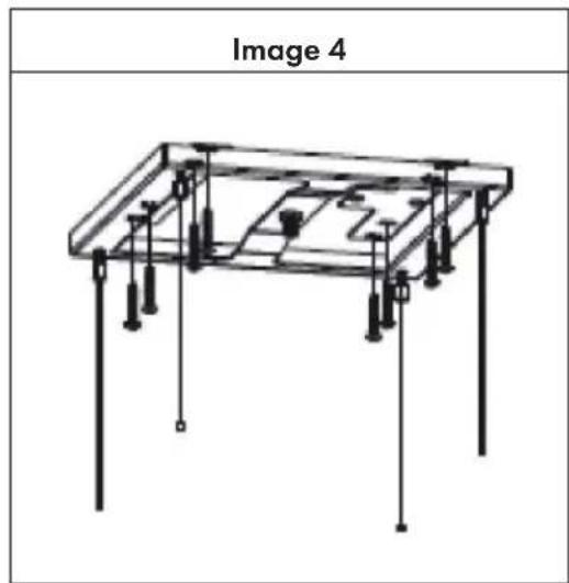
- Drill 8 mounting holes on the ceiling corresponding to the 8 round holes on the hanging board and fix the hanging board to the wooden ceiling with 8 countersunk screws (ST640 mm) (see image 4). If the ceiling is made of concrete, you must drill 4 mounting holes corresponding to the 4 holes on the hanging board and use four countersunk screws(Ø660) to fix the hanging board to the ceiling.
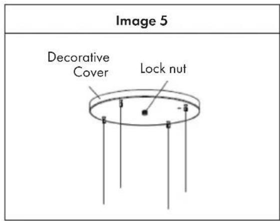
- Attach the 4 wire ropes to the cover and use the locking nut to secure the cover to the suspension board. (See image 5). Note that the hole for the power cable on the cover plate should be in the same direction as the hole for the power cable on the cooker bonnet.
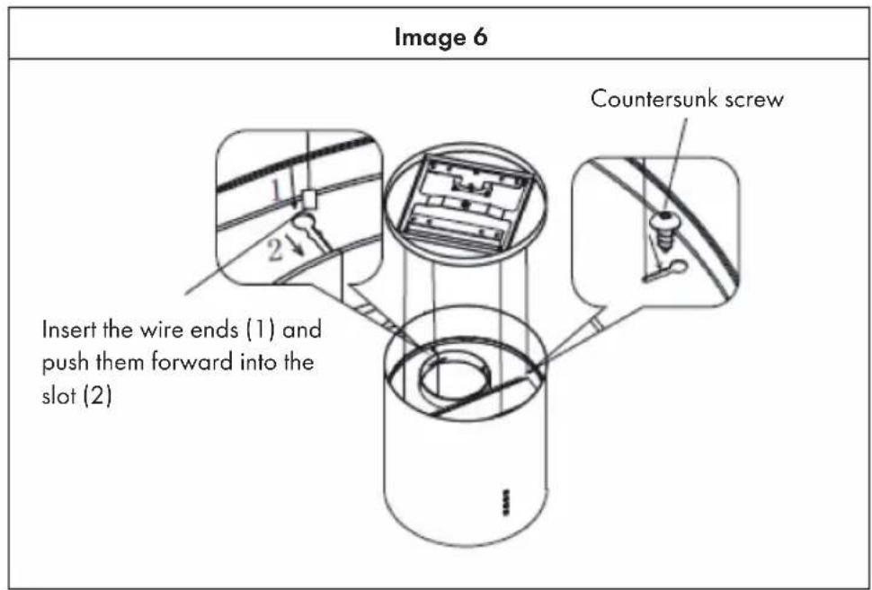
- Follow steps 1 and 2 on image 6 to insert the 4 wire ropes into the slot of the top plate of the cooker bonnet and use four countersunk screws (ST4*8 mm) to fix the wire ropes and prevent them from slipping out again (see image 6).
-
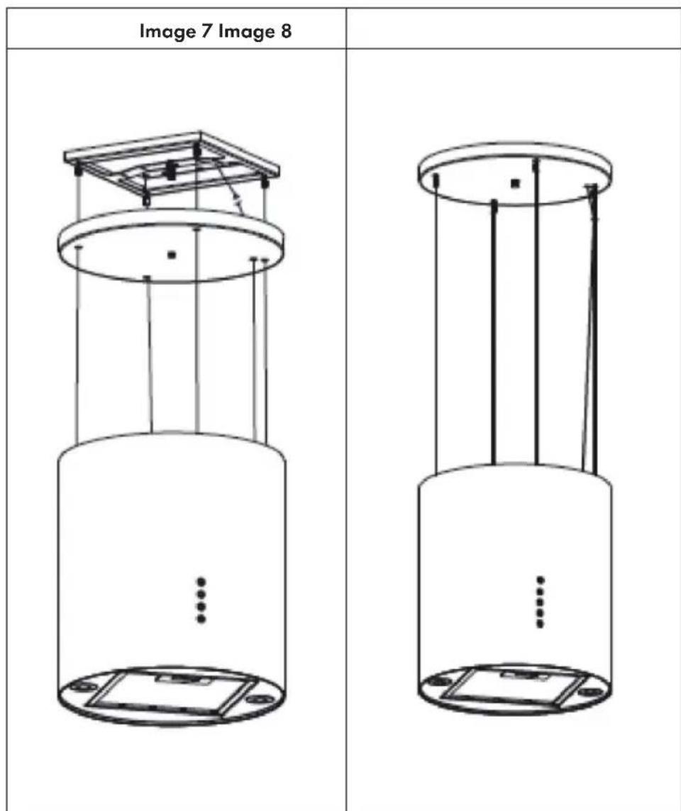
Loosen the cover plate. Then guide the power cable of the cooker bonnet through the cover plate and connect it to the power cable coming out of the ceiling. Make sure that the power cable is well wrapped with insulating tape to avoid electric shock (see image 7).
-
Loosen the four adjusting screws and align the bonnet horizontally. Tighten the 4 wire ropes evenly in a clockwise direction. Reattach the cover plate and secure the power cable with the cable tie along the wire rope (see image 8). The installation is now complete.
NOTES FOR THE INSTALLATION OF THE EXHAUST AIR PIPE
The following rules must be strictly observed to achieve optimum air extraction:
- Make sure that the exhaust pipe extends as short and straight as possible.
- Do not reduce the size or restrict the exhaust pipe.
When using exhaust air pipes, always install the pipe tightly to minimise pressure loss. - Non-compliance with these basic instructions will reduce the performance and increase the noise level of the cooker bonnet.
- All installation work must be carried out by an electrician or a qualified person.
- Do not connect the exhaust pipe of the bonnet to an existing ventilation system used for another appliance, e.g. a flue, gas pipes or hot air pipes.
- In case the exhaust air pipe is bent, the angle of the exhaust air pipe should not be less than 120^ . Never point the exhaust air pipe downwards, but always horizontally or guide the pipe from the starting point upwards to the air outlet on the outside wall.
- After installation, please make sure that the cooker bonnet is positioned horizontally to prevent grease from accumulating.
- Make sure that the exhaust pipe selected for installation complies with the relevant standards and is fire-retardant.

CAUTION
Risk of injury! For safety reasons, only use the size of fastening or mounting screw recommended in these operating instructions. Non-compliance with these instructions can lead to injuries and electric shocks.
CONTROL PANEL AND FUNCTION KEYS
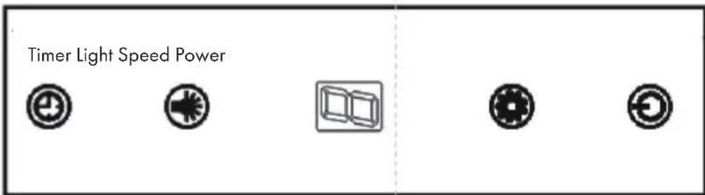
- Press the POWER button to switch the extractor bonnet on and off.
- Press the SPEED button several times to run the motor at the following power: low > medium > high > low. The display shows the corresponding speed: 1 > 2 > 3 > 1 .
- Press the LIGHT button to switch on the light. Press the button again to switch it off.
- When the bonnet is in operation and the TIMER button is pressed, the bonnet switches to timer mode. The default setting is 9 minutes. The timer then starts counting down the time. The remaining time is shown in the display: 9 > 8 > 7 > 6 > 5 > 4 > 3 > 2 > 1 > 0 . When [0] is shown, the bonnet is automatically switched off. Press and hold the TIMER button to deactivate the timer again.
REMOTE CONTROL AND FEATURES
Lighting
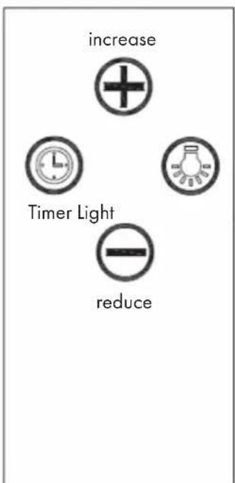
Press the LIGHT button to switch on the light. Press the button again to switch it off. The light is independent of other functions.
Increase speed
The motor offers 3 speed levels: low, medium and high.
- Press the SPEED button once to run the motor at low speed.
- Press the SPEED button twice to run the motor at medium speed.
- Press the SPEED button 3 times to run the motor at high speed.
Reduce speed
Each time you press the [-] button, the speed is reduced to the next level. The display indicates the corresponding speed. If you want to switch off the motor, press the [-] button until the motor stops.
Setting the timer
1 Press the TIMER button to activate the timer function. The timer is initially set to 5 minutes. Each time you press [+] , the time is increased by 1 minute. Each time you press [-] , the time is reduced by 1 minute. A time of 1-60 minutes can be set.
2 Once you have set the timer, press the TIMER button again to confirm or wait 10 seconds until the set time is automatically accepted. The motor runs until the timer has counted down the time, then it switches off automatically.
3 In case you want to use the set time again the next time, just press the TIMER button and then wait 10 seconds until the last set time is applied. If you want to enter a different time, proceed as described in steps 1 and 2. After the timer has been confirmed, the motor continues to run until the timer has counted down the time.
Note: If you want to end an active timer prematurely, press the TIMER button again while the timer is running.
TROUBLESHOOTING
| Problem Potential cause | Possible solution | |
| The light turns on but the engine does not run. | The motor is switched off. Switch on the motor with the SPEED button. | |
| The motor switch is broken. Contact a specialist company. | ||
| The motor is broken. Contact a specialist company. | ||
| Lights and engine do not work. | Your mains security fuse is flipped or broken. | Flip the fuse switch or replace the fuse |
| The power cable is loose or not connected. | Connect the power cord correctly. | |
| The light does not work. The unsatisfactory suction performance | light is broken. Replace the bulb. | |
| The distance between the cooker and the extractor bonnet is too far. | Reduce the distance. | |
| The extractor bonnet hangs crooked. | One of the fixing screws is not properly tightened. | Tighten the screw securely. |
CLEANING AND CARE
Before maintenance or cleaning, the cooker bonnet should always be disconnected from the power supply. Make sure that the cooker bonnet is switched off and the plug has been removed. Exterior surfaces are prone to scratches and dents. Therefore, please follow the cleaning instructions to achieve the best possible result without damage.
General information
Allow the appliance to cool down completely before cleaning and maintenance and do not use alkaline or acidic substances such as lemon juice or vinegar to clean the surface.
Stainless steel
The stainless steel must be cleaned regularly (weekly) to ensure a long service life. A special stainless steel cleaning fluid can be used for this purpose.
Control panel
The control panel can be cleaned with warm soapy water. Make sure the cloth is clean and thoroughly wrung out before cleaning the control panel. Use a dry, soft cloth to remove excess moisture after cleaning.
Important: Use neutral cleaning agents and avoid using harsh cleaning chemicals, strong household cleaners or products containing abrasive cleaners as this will affect the appearance of the appliance and may remove the printed symbols on the control panel.
Grease filter
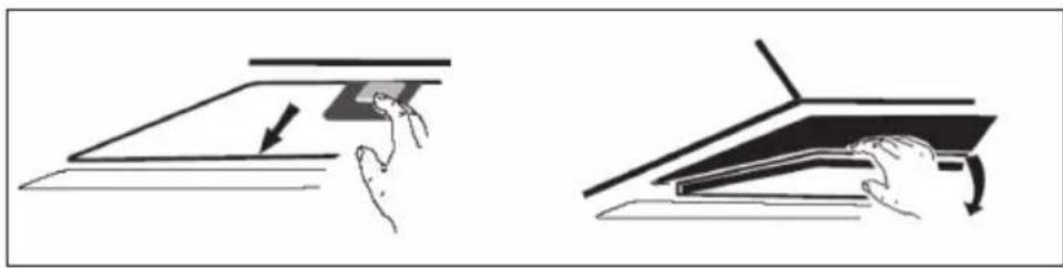
The fabric filters can be cleaned by hand. Soak them in water together with a grease-dissolving detergent for about 3 minutes and then brush them gently with a soft brush. Do not apply too much pressure to avoid damaging the filter. Allow the filter to air dry afterwards, but do not place it directly in the sun. Filters should always be washed separately from crockery and kitchen utensils!
Remove the filter as shown in the image on the right and then reinsert the filter in the reverse order.
Activated carbon filter
Activated carbon filters can be used to remove odours. Normally, the activated charcoal filter should be changed after three or six months, depending on your cooking habits. The installation of the activated carbon filter is done as follows:
- Disconnect the extractor bonnet from the power supply before installation.
- Press the filter lock and remove the mains filter.
3 Rotate the carbon filter counter-clockwise on both sides of the motor. Replace the old carbon filters with new carbon filters.
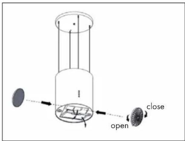
4 Replace the mains filter.
5 Reconnect the power cord to the power socket.
Note: Make sure that the filter is tightly closed. It can otherwise detach and become dangerous. If an activated carbon filter is connected, the suction power is reduced.
Replace the light bulb
- The lamp must be replaced by the manufacturer, its after-sales service or similarly qualified persons.
- Always switch off the power supply before carrying out any work on the appliance. When handling the light bulb, make sure that it has cooled down completely before touching it directly with your hands.
- Always hold the light bulb with a cloth or gloves when inserting or removing it to ensure that sweat does not come into contact with the lamp, as this can reduce its life.
To replace the light bulb:
1 Before changing the lighting, make sure that the cooker bonnet is switched off.
2 Rotate the cover counter-clockwise. Loosen the screw of the stainless steel filter and remove it.
3 Press the light connector to remove the light bulb.
4 Install the new light and reconnect the cable.
Important information about the illuminant
| LED type: Round glass lamp |
| Maximum wattage: 1 W |
| Voltage range: DC 4V |
| Dimensions: see illustration |
PRODUCT DATA SHEET
Information according to Regulation (EU) No 65/2014
Measurement and calculation methods according to EN 61591:1997+A1:2006+A2:20 11+A11:2014+A12:2015
| Item number | 10032301, 10032302, 10032303, 10035165 | ||
| Designation Symbol Value Unit | |||
| Annual energy consumption AECood | 57.9 kWh/year | ||
| Energy efficiency class B | |||
| fluid-dynamic efficiency FDEhood 22.1 | |||
| Fluid dynamic efficiency class C | |||
| Lighting efficiency LEhood | 102.5 Lux/W | ||
| Lighting efficiency class | A | ||
| Grease separation efficiency | GFEhood | 79.3 | % |
| Class for grease separation efficiency | C | ||
| Airflow at minimum and at maximum speed in normal operation, excluding operation on the intensive or fast speed setting | 317.8 / 537.8 | m³/h | |
| Air flow when operating on the intensive or fast speed setting | - m³/h | ||
| A-weighted airborne noise emissions at minimum and maximum available speed during normal operation | 62 / 72 dB | ||
| A-weighted airborne acoustical noise emissions during operation at the intensive or high-speed stage | - | dB | |
| Power consumption in off-mode | Po | 0.36 | W |
| Power consumption in standby mode | Ps | - | W |
| Contact details | Chal-Tec GmbH, Wallstraße 16, 10179 Berlin, Germany. | ||
Information according to Regulation (EU) No 66/2014
Measurement and calculation methods according to EN 61591:1997+A1:2006+A2:20 11+A11:2014+A12:2015
| Item number | 10032301, 10032302, 10032303, 10035165 | ||
| Designation Symbol Value Unit | |||
| Annual energy consumption AEChood | 57.9 kWh/year | ||
| Time extension factor f 1.2 | |||
| fluid-dynamic efficiency FDEhood 22.1 | |||
| Energy efficiency index EElhood 66.3 | |||
| Measured air volume flow at the optimum level | QBEP | 291.8 | m³/h |
| Measured air pressure at the optimum level | PBEP | 351 Pa | |
| Maximum air flow Qmax 557.5 | m³/h | ||
| Measured electrical input power at the optimum level | WBEP 128.9 | W | |
| Rated power of the lighting system | WL | 2.0 | W |
| Average illuminance of the lighting system on the cooking surface | Emiddle | 205 | Lux |
| Measured power consumption in standby mode | Po | - | W |
| Measured power consumption in off-mode | Ps | 0.36 | W |
| Sound power level | LWA | 62 / 72 dB | |
| Contact details | Chal-Tec GmbH, Wallstraße 16, 10179 Berlin, Germany. | ||
NOTES ON ENVIRONMENTAL PROTECTION
- Make sure there is sufficient air supply during cooking so that the cooker bonnet can work efficiently and with low operating noise.
- Adjust the fan speed to the amount of steam produced while cooking. Use the intensive mode only when necessary. The lower the fan speed, the less energy is consumed.
- If large amounts of steam are produced when cooking, select a higher fan speed in time. If the cooking steam has already spread throughout the kitchen, the cooker bonnet must be operated for longer.
- Switch off the cooker bonnet when it is no longer needed.
- Switch off the lighting when it is no longer needed.
- Clean the filter at regular intervals and replace it if necessary to increase the effectiveness of the ventilation system and prevent fire hazards.
Always put the lid on when cooking to reduce cooking steam and condensation.
DISPOSAL CONSIDERATIONS
If there is a legal regulation in your country regarding the disposal of electrical and electronic equipment, this symbol on the product or on the packaging indicates that this product must not be disposed of with household waste. Instead, it must be taken to a collection point for the recycling of electrical and electronic equipment. By disposing of this product in accordance with the regulations, you protect the environment and the health of those around you from negative consequences. For information on recycling and disposal of this product, contact your local government or household waste disposal service.
This product contains batteries. If there is a legal regulation in your country regarding the disposal of batteries, the batteries must not be disposed of in household waste. Consult your local regulations for the disposal of batteries. By disposing of this product in accordance with the regulations, you protect the environment and the health of those around you from negative consequences.
MANUFACTURER & IMPORTER (UK)
Manufacturer:
Chal-Tec GmbH, Wallstraße 16, 10179 Berlin, Germany.
Importer for Great Britain:
Berlin Brands Group UK Ltd
PO Box 1145
Oxford,OX1 9UW
United Kingdom
Estimado cliente:
Berlin Brands Group UK Ltd
PO Box 1145
Oxford,OX1 9UW
United Kingdom
Cher client, chere clientele,
FICHE DE DONNÉES PRODUIT
Berlin Brands Group UK Ltd
PO Box 1145
Oxford, OX1 9UW
United Kingdom
Gentile cliente,
PRODUTTORE IMPORTATORE (UK)
Produtlore:
Chal-Tec GmbH, Wallstraße 16, 10179 Berlin, Germania.
Berlin Brands Group UK Ltd
PO Box 1145
Oxford,OX1 9UW
United Kingdom
Bästa kund,
INSTALLATION (EXTERNAL VENTILATION)
Berlin Brands Group UK Ltd
PO Box 1145
Oxford,OX1 9UW
United Kingdom

KLARSTEIN