
SERIES 8p Dyna - Receiver TASCAM - Free user manual and instructions
Find the device manual for free SERIES 8p Dyna TASCAM in PDF.
| Type de produit | 8-Channel Microphone Preamplifier |
| Dimensions (L × H × P) | 482 × 44.8 × 228.8 mm (with protrusions) |
| Poids | 2.6 kg |
| Alimentation | DC 12 V AC adapter (PS-P1230) supplied with 3 interchangeable plug sets |
| Consommation électrique | 16 W |
| Entrées audio | 8 balanced XLR/6.35 mm TRS jack combo inputs (MIC/LINE); channels 1-2 also feature high-impedance instrument (INST) input |
| Sorties audio analogiques | 8 balanced outputs on D-Sub 25-pin (ANALOG OUT); 8 balanced outputs on 6.35 mm TRS jacks (LINE OUT 1-8) |
| Sorties audio numériques | 2 S/MUX optical ports (supports S/MUX2 and S/MUX4); up to 8 channels at 44.1/48 kHz, 4 channels at 88.2/96 kHz, 2 channels at 176.4/192 kHz |
| Alimentation fantôme | +48 V switchable independently per channel (dedicated switches) |
| Compresseur | Analog per-channel compressor, single-knob, ratio 3:1, threshold adjustable over 30 dB, true bypass |
| Horloge et synchronisation | Selectable internal clock; BNC Word Clock input/output with 75 Ω ON/OFF/THRU/WORD OUT selector; supports frequencies 44.1 to 192 kHz |
| Indicateurs | Overload (OL) indicator, compressor active indicator, phantom power indicator, sample clock indicator; LED level meters |
| Montage en rack | Screw kit supplied for 19-inch rack; leave 1U above and 10 cm at the rear for ventilation |
| Plage de température de fonctionnement | 0 to 40 °C |
| Entretien et nettoyage | Wipe with a soft dry cloth; do not use chemical cleaners, thinner, or alcohol |
| Sécurité | Do not expose to dripping or splashing; do not open the case (no user-serviceable parts); unplug during storms or if not used for extended periods |
| Pièces détachées et réparabilité | AC adapter (PS-P1230) available; repair only by qualified technicians; contact your dealer or TASCAM support |
| Accessoires fournis | Main unit, AC adapter with 3 plug sets, rack-mount screw kit, instruction manual including warranty |
| Informations générales | Complies with European directives; TEAC website for manual download; rating plate under the unit |
Frequently Asked Questions - SERIES 8p Dyna TASCAM
User questions about SERIES 8p Dyna TASCAM
0 question about this device. Answer the ones you know or ask your own.
Ask a new question about this device
Download the instructions for your Receiver in PDF format for free! Find your manual SERIES 8p Dyna - TASCAM and take your electronic device back in hand. On this page are published all the documents necessary for the use of your device. SERIES 8p Dyna by TASCAM.
USER MANUAL SERIES 8p Dyna TASCAM
TASCAM is a registered trademark of TEAC Corporation.
- Other company names, product names and logos in this document are the trademarks or registered trademarks of their respective owners.
TEAC CORPORATION
https://tascam.com/us/
Phone: +1-323-726-0303
10410 Pioneer Blvd. Suite #1, Santa Fe Springs,
California 90670, U.S.A.
TEAC UK Ltd.
https://www.tascam.eu/en/
Phone: +44-1923-797205
Meridien House, 69-71 Clarendon Road, Watford, Herts,
WD17 1DS, United Kingdom
TEAC EUROPE GmbH
https://www.tascam.en/de/
Phone: +49-611-71580
Room 817, Xinian Center A, Tairan Nine Road West,
Shennan Road, Futian District, Shenzhen,
Guangdong Province 518040, China
IMPORTANT SAFETY INSTRUCTIONS
WARNING: TO PREVENT FIRE OR SHOCK HAZARD, DO NOT EXPOSE THIS APPLIANCE TO RAIN OR MOISTURE.
For U.S.A.
Declaration of Conformity
Model Number: SERIES 8p Dyna
Trade Name:TASCAM
Responsible party: TEAC AMERICA, INC.
Address: 10410 Pioneer Blvd. Suite #1, Santa Fe Springs, California 90670, U.S.A.
Telephone number: 1-323-726-0303

This device complies with Part 15 of the FCC Rules. Operation is subject to the following two conditions: (1) this device may not cause harmful interference, and (2) this device must accept any interference received, including interference that may cause undesired operation.
INFORMATION TO THE USER
This equipment has been tested and found to comply with the limits for a Class B digital device, pursuant to Part 15 of the FCC Rules. These limits are designed to provide reasonable protection against harmful interference in a residential installation.
This equipment generates, uses, and can radiate radio frequency energy and, if not installed and used in accordance with the instruction manual, may cause harmful interference to radio communications. However, there is no guarantee that interference will not occur in a particular installation.
If this equipment does cause harmful interference to radio or television reception, which can be determined by turning the equipment off and on, the user is encouraged to try to correct the interference by one or more of the following measures.
a) Reorient or relocate the receiving antenna.
b) Increase the separation between the equipment and receiver.
c) Connect the equipment into an outlet on a circuit different from that to which the receiver is connected.
d) Consult the dealer or an experienced radio/TV technician for help.
CAUTION
Changes or modifications to this equipment not expressly approved by TEAC CORPORATION for compliance could void the user's authority to operate this equipment.
For Canada
THIS CLASS B DIGITAL APPARATUS COMPLIES WITH CANADIAN ICES-003.
CET APPAREIL NUMERIQUE DE LA CLASSE B EST CONFORME A LA NORME NMB-003 DU CANADA.

This product complies with the European Directives request and the other Commission Regulations.
- Read these instructions.
- Keep these instructions.
- Heed all warnings.
- Follow all instructions.
- Do not use this apparatus near water.
- Clean only with dry cloth.
- Do not block any ventilation openings. Install in accordance with the manufacturer's instructions.
- Do not install near any heat sources such as radiators, heat registers, stoves, or other apparatus (including amplifiers) that produce heat.
- Do not defeat the safety purpose of the polarized or grounding-type plug. A polarized plug has two blades with one wider than the other. A grounding type plug has two blades and a third grounding prong. The wide blade or the third prong are provided for your safety. If the provided plug does not fit into your outlet, consult an electrician for replacement of the obsolete outlet.
- Protect the power cord from being walked on or pinched particularly at plugs, convenience receptacles, and the point where they exit from the apparatus.
- Only use attachments/accessories specified by the manufacturer.
- Use only with the cart, stand, tripod, bracket, or table specified by the manufacturer, or sold with the apparatus. When a cart is used, use caution when moving the cart/ apparatus combination to avoid injury from tip-over.

- Unplug this apparatus during lightning storms or when unused for long periods of time.
- Refer all servicing to qualified service personnel. Servicing is required when the apparatus has been damaged in any way, such as power-supply cord or plug is damaged, liquid has been spilled or objects have fallen into the apparatus, the apparatus has been exposed to rain or moisture, does not operate normally, or has been dropped.
The apparatus draws nominal non-operating power from the AC outlet with its POWER or STANDBY/ON switch not in the ON position. - The mains plug is used as the disconnect device, the disconnect device shall remain readily operable.
- Caution should be taken when using earphones or headphones with the product because excessive sound pressure (volume) from earphones or headphones can cause hearing loss.
If you are experiencing problems with this product, contact TEAC for a service referral. Do not use the product until it has been repaired.
CAUTION
- Do not expose this apparatus to drips or splashes.
- Do not place any objects filled with liquids, such as vases, on the apparatus.
- Do not install this apparatus in a confined space such as a book case or similar unit.
- The apparatus should be located close enough to the AC outlet so that you can easily grasp the power cord plug at any time.
If the product uses batteries (including a battery pack or installed batteries), they should not be exposed to sunshine, fire or excessive heat. - CAUTION for products that use replaceable lithium batteries: there is danger of explosion if a battery is replaced with an incorrect type of battery. Replace only with the same or equivalent type.
For European Customers
Disposal of electrical and electronic equipment
(a) All electrical and electronic equipment should be disposed of separately from the municipal waste stream via collection facilities designated by the government or local authorities.
(b) By disposing of electrical and electronic equipment correctly, you will help save valuable resources and prevent any potential negative effects on human health and the environment.
(c) Improper disposal of waste electrical and electronic equipment can have serious effects on the environment and human health because of the presence of hazardous substances in the equipment.
(d) The Waste Electrical and Electronic Equipment (WEEE) symbol, which shows a wheeled bin that has been crossed out, indicates that electrical and electronic equipment must be collected and disposed of separately from household waste.

(e) Return and collection systems are available to end users. For more detailed information about the disposal of old electrical and electronic equipment, please contact your city office, waste disposal service or the shop where you purchased the equipment.
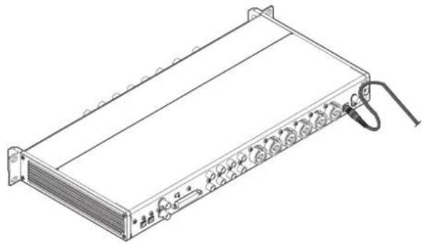
RACK-MOUNTING THE UNIT
Use the supplied rackmount screw kit to mount the unit in a standard 19-inch rack, as shown below.
Remove the feet of the unit before mounting.
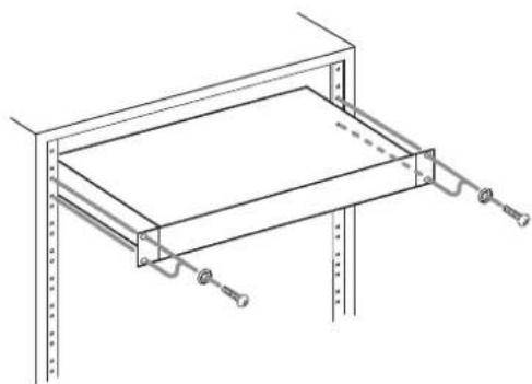
ATTENTION
- Leave 1U of space above the unit for ventilation.
- Allow at least 10cm (4 in) at the rear of the unit for ventilation.
CAUTION
DO NOT REMOVE THE EXTERNAL CASES OR CABINETS TO EXPOSE THE ELECTRONICS. NO USER SERVICEABLE PARTS ARE INSIDE.
IF YOU ARE EXPERIENCING PROBLEMS WITH THIS PRODUCT, CONTACT THE STORE WHERE YOU PURCHASED THE UNIT FOR A SERVICE REFERRAL. DO NOT USE THE PRODUCT UNTIL IT HAS BEEN REPAIRED.
USE OF CONTROLS OR ADJUSTMENTS OR PERFORMANCE OF PROCEDURES OTHER THAN THOSE SPECIFIED HEREIN MAY RESULT IN HAZARDOUS RADIATION EXPOSURE
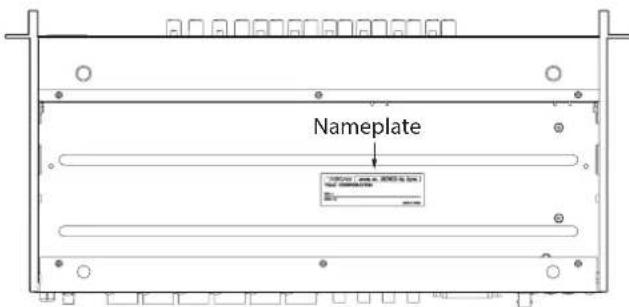
The nameplate is located on the bottom of the unit as shown below.
Front side
Contents
IMPORTANT SAFETY INSTRUCTIONS 3
Introduction. 5
Features. 5
Included items 6
Conventions used in this manual 6
About TASCAM customer support service. 6
Precautions for placement and use. 6
Beware of condensation 6
Cleaning the unit 6
Product registration.. 6
Using the TEAC Global Site 6
Names and functions of parts 7
Front panel. 7
Rear panel. 9
Connecting the power. 10
Changing the outlet plug 10
Connecting other equipment 11
Audio connections 11
Switching the sample clock 12
Synchronizing with digital devices 13
Making connections to use an OPTICAL OUT (S/MUX) of this unit as the clock master. 13
Making connections to use the word clock of this unit as the clock master. 14
Making connections to use the word clock of a connected unit as the clock master. 15
Connecting two of these units to synchronize them 16
Specifications. 17
Ratings 17
Analog audio input ratings 17
Analog outputs. 17
Digital audio output ratings 17
Control input/output. 17
Audio performance. 18
General 18
Dimensional drawings 18
Introduction
Thank you very much for purchasing a TASCAM SERIES 8p Dyna MICROPHONE PREAMP.
Before connecting and using this unit, please take time to read this manual thoroughly to ensure you understand how to properly set it up and connect it, as well as how to use its many useful and convenient functions. After you have finished reading this manual, please keep it in a safe place for future reference.
You can also download this Owner's Manual from the TEAC Global Site (http://teac-global.com/).
Features
TASCAM HDIA mic preamps use instrumentation amplifiers and have outstanding specifications, enabling them to provide clear natural sound with super-low noise
Support for high-resolution recording formats up to 24-bit/192kHz
- 8 balanced combo XLR/TRS combo input jacks
- Channel 1–2 instrument (INST) inputs on the front for guitars, basses and other instruments with high-impedance output
+48V phantom power can be provided to each input channel independently
Each input channel has its own single-knob analog compressor that includes true bypass
- Analog overload, compressor and digital indicators as well as level meters on the front panel
- 2 S/MUX optical ports can output all 8 usable inputs even when 96kHz sampling is used
- 8 outputs at 44.1 / 48kHz
- 8 outputs at 88.2/96kHz
- 4 outputs at 176.4 / 192kHz
25P D-Sub and 8 TRS analog balanced outputs support a variety of connections with other equipment
IN/OUT BNC connectors (with IN/OUT/THRU switch) for flexible audio clock connections
- AC adapter (PS-P1230) included with 3 alternate plugs
Included items
This product includes the following items.
Take care when opening the package to avoid damaging the items. Keep the box and packing materials for transportation in the future.
Please contact the store where you purchased this unit if any of these items are missing or have been damaged during transportation.
- Main unit. x 1
AC adapter (PS-P1230) (with 3 alternate plugs)..x 1
Rackmount screw kit. x 1
Owner's Manual (this document) including warranty..x 1
ATTENTION
Always use the included AC adapter (PS-P1230) when using this unit. Never use the included AC adapter with any other device. Doing so could cause damage, fire or electric shock.
NOTE
The included AC adapter (PS-P1230) is shipped with alternate outlet plugs. Please see "Changing the outlet plug" on page 10.
Conventions used in this manual
As necessary, additional information is provided under TIP, NOTE and CAUTION headings.
TIP
These are tips about how to use the unit.
NOTE
These provide additional explanations and describe special cases.
ATTENTION
Failure to follow these instructions could result in damage to equipment or lost data, for example.
CAUTION
Failure to follow these instructions could result in injury.
About TASCAM customer support service
TASCAM products are supported and warranted only in their country/region of purchase.
To receive support after purchase, on the TASCAM Distributors list page of the TEAC Global Site (http://teac-global.com/), search for the local company or representative for the region where you purchased the product and contact that organization.
When making inquiries, the address (URL) of the shop or web shop where it was purchased and the purchase date are required. Moreover, the warranty card and proof of purchase might also be necessary.
Precautions for placement and use
The operating temperature range of this unit is 0 - 40^
- Do not install this unit in the following types of locations. Doing so could make the sound quality worse or cause malfunction.
Places with significant vibrations
Next to a window or in another location exposed to direct sunlight
Near heaters or other extremely hot places
Extremely cold places
Very humid or poorly ventilated places
Very dusty places
- To enable good heat dissipation, do not place anything on top of the unit.
- Do not place this unit on top of a power amplifier or other device that generates heat.
Beware of condensation
Condensation could occur if the unit is moved from a cold place to a warm place, it is used immediately after a cold room has been heated or it is otherwise exposed to a sudden temperature change.
To prevent this, or if this occurs, let the unit sit for one or two hours at the new room temperature before using it.
Cleaning the unit
Use a dry soft cloth to wipe the unit clean. Do not wipe with chemical cleaning cloths, thinner, alcohol or other chemical agents. Doing so could damage the surface or cause discoloration.
Product registration
Customers in the USA, please visit the following TASCAM website to register your TASCAM product online.
https://tascam.com/us/
Using the TEAC Global Site
You can download updates for this unit from the TEAC Global Site:
http://teac-global.com/
In the TASCAM Downloads section, select the desired language to open the Downloads website page for that language.
Front panel
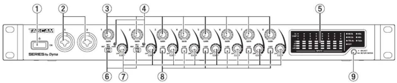
① switch
Press to turn the unit on and to put it into standby.
② 1-2 input jacks
These analog inputs are XLR/TRS combo jacks.
They can support high impedance input, including direct guitar input.
- XLR (1: GND, 2: HOT, 3: COLD)
- TRS (Tip: HOT, Ring: COLD, Sleeve: GND)
Use the input switches (6) to select balanced line (MIC/LINE) or high-impedance (INST) input for the TRS jacks.
When directly connecting a guitar, bass or other highimpedance output, set the input switch () to INST.
Use the GAIN knobs (1-2) to set input gains.
③ GAINknobs
Use GAIN knobs 1-8 to adjust the input gain of each channel independently.
④ + 48V indicators
These indicators light when their input switches (6) are set to +48V .
⑤ Level meter area
This shows input signal levels.
⑥ Input switches
Set according to the input sources of input jacks 1-2.
INST: Select when directly connecting a guitar, bass or other high-impedance instrument. This makes it an unbalanced input for high impedance.
MIC/LINE: Select when connecting a balanced-output mic or line-level-output device.
+48V: This provides +48V phantom power to the 1-2 XLR input jacks.
ATTENTION
- Do not connect or disconnect mics when these switches are set to +48V .
- Do not supply phantom power to an unbalanced dynamic mic.
- Supplying phantom power to some ribbon mics will break them. If you are unsure, do not supply phantom power to a ribbon mic.
⑦ COMP knobs
Use these knobs to adjust the threshold levels, which are the levels when compression begins to be applied to the signals input to each channel.
⑧ + 48V switch/indicator
Use these switches to supply +48V phantom power to the MIC/LINE INPUT 3-8 jacks on the back of the unit.
Phantom power can be set for each input channel independently.
When the +48V switch is on, it lights and provides +48V phantom power to the XLR connector of the input jack.
ATTENTION
- Do not connect or disconnect mics when a switch is on.
- Do not supply phantom power to an unbalanced dynamic mic.
- Supplying phantom power to some ribbon mics could break them. If you are unsure, do not supply phantom power to a ribbon mic.
9 Sample clock switch
Set the sample clock source to the unit's internal clock, and set the sampling frequency. (see "Switching the sample clock" on page 12)
The sample clock indicators (13) light according to the currently active sampling frequency being used by the unit
Level meter area details
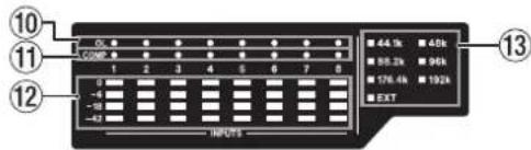
⑩ OL indicators
These light when input signals reach 3 dB below the maximum input level.
Check if they are lighting and adjust the input gain.
1 COMP indicators
These indicators light dimly when compressors are enabled. They light brightly when compressors are activated by input signals exceeding their threshold values.
12 Level meters
This shows input signal levels after input gain adjustments.
③ Sample clock indicators
These indicators light according to the sampling frequency currently used by the unit.
When the EXT indicator is lit, the unit is using external clock. When in sample clock source set up mode, the selected sample clock source will blink repeatedly at short intervals. (see "Switching the sample clock" on page 12)
NOTE
-
When operating using external clock, the EXT indicator will blink when external clock is not being input. When this happens, the unit will automatically switch to internal clock.
-
When the EXT indicator is blinking (when the unit has automatically switched to internal clock because external clock is not being input even though set to use external clock), that clock frequency will also start blinking if external clock is input again.
Rear panel
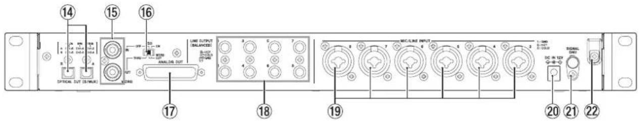
14 OPTICAL OUT (S/MUX) connectors
These connectors output multichannel digital audio in optical format.
44.1, 48, 88.2, 96, 176.4 and 192kHz sampling frequencies are supported.
88.2/96 kHz is supported by S/MUX2, and 176.4/192 kHz is supported by S/MUX4.
As shown below, the outputs of these two connectors depend on the sampling frequency.
| Sampling frequencies A | B | |
| 44.1/48 kHz Channels 1-8 | Channels 1-8 | |
| 88.2/96 kHz Channels 1-4 | Channels 5-8 | |
| 176.4/192 kHz Channels | 1-2 Channels 3-4 |
NOTE
S/PDIF format will not be output.
15 WORD IN/OUT connectors
These BNC connectors are for the input and output of word clock signals.
Word clock signals of 44.1, 48, 88.2, 96, 176.4 and 192kHz can be input and output.
ATTENTION
If a digital system has multiple word clock masters, serious problems, including damage to equipment, could occur.
16 75Ω ON/OFF/THRU/WORD OUT switch
Use this switch to make the following settings.
- Whether or not the WORD IN connector has 75
termination - WORD output THRU/OUT setting (OUT is for WORD only)
⑦ ANALOG OUT connector
This is a 25-pin D-Sub balanced analog output connector. The nominal output level is +4dB
Use an analog output D-Sub multi-cable to connect this to an external balanced analog input device and transmit signals for channels 1-8.
The pin assignments* of the ANALOG OUT connector are as shown below.
- Pin assignments adhere to the TASCAM DB-25 Pinout Standard (AES59-2012)
ANALOG OUT
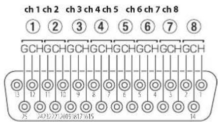
G: GND, C: COLD, H: HOT
ATTENTION
If devices are connected to the LINE OUTPUT jacks at the same time but are not turned on, the quality of the output from the ANALOG OUT connector could be degraded.
18 LINE OUT (BALANCED) 1-8 jacks
These standard TRS jacks are balanced analog line outputs. The nominal output level is +4 dBu. (Tip: HOT, Ring: COLD, Sleeve: GND)
ATTENTION
If a device is connected to the ANALOG OUT connector at the same time but is not turned on, the quality of the output from the LINE OUT jacks could be degraded.
MIC/LINE INPUT 3-8 jacks
These analog inputs are XLR/TRS combo jacks. These jacks support line input from audio equipment and keyboards, for example.
XLR (1: GND, 2: HOT, 3: COLD)
- TRS (Tip: HOT, Ring: COLD, Sleeve: GND)
Use the GAIN knobs (3-8) on the front of the unit to set input gains.
NOTE
When phantom power is on, +48V phantom power is supplied to XLR connectors. No power is supplied to the TRS connectors.
DCIN 12V connector
Connect the included AC adapter (PS-P1230) here.
2 SIGNAL GND connector
This is a ground connector for audio signals.
ATTENTION
This connector is not a power supply grounding connection.
Cord holder
Hook the cord of the included PS-P1230 AC adapter here to prevent accidental disconnection
Connecting the power
Use the included AC adapter (PS-P1230) to connect a power supply to the unit as shown below.
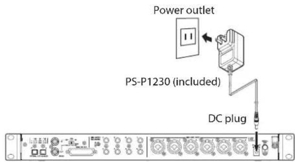
In order to prevent the cord from becoming disconnected during use, wrap it around the cord holder when connecting it.
ATTENTION
Always use the AC adapter (PS-P1230) that was shipped with the unit. Using a different AC adapter could cause malfunction, overheating, fire or other problems.
NOTE
The AC adapter for the unit includes 3 types of outlet plugs. Attach the type of plug that matches the power outlet that you are using. (see "Changing the outlet plug" on page 10)
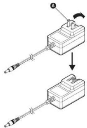
Changing the outlet plug
NOTE
When purchased new, the included PS-P1230 AC adapter for the unit has an outlet plug (A) already attached.
Follow the procedures below to attach and use a different outlet plug (B - D) if necessary.
- Fold the outlet plug (A) on the PS-P1230 AC adapter in the direction of the arrow.
-
Select the plug that matches the AC outlet from the 3 other types included (B, C or D).
-
Attach the outlet plug to the AC adapter.
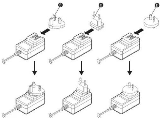
This completes changing the outlet plug.
After changing the outlet plug, confirm that it is not loose or crooked and that everything is normal before plugging it into an outlet.
ATTENTION
Do not use the adapter if there is anything abnormal about the plug after changing it. Use when the plug is abnormal could cause fire or electric shock. Contact the retailer where you purchased the unit or a TASCAM customer support service to request repair.
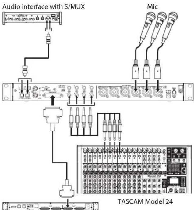
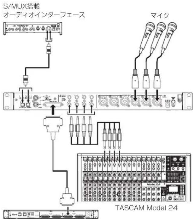
Connecting other equipment
These are examples of SERIES 8p Dyna connections.
Precautions before making connections
- Carefully read the operation manuals of the devices to be connected and then connect them correctly.
Before making connections, turn this unit and all equipment to be connected off (standby). - If possible, install all connected devices so that they are powered from the same AC power supply line. When using a power strip or similar device, be sure to use one that has a thick cable with high current capacity in order to minimize voltage fluctuations in the AC power supply.
TASCAM ML-16D
Examples of connections with a SERIES 8p Dyna
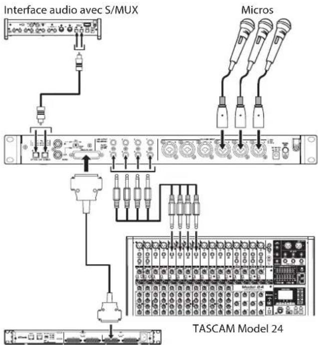
Audio connections
Analog audio signals input into this device from mics, guitars, keyboards and other audio equipment can be output to connected devices as analog output from the 25-pin D-Sub and TRS balanced outputs as well as converted into digital signals and transmitted from the S/MUX connectors. In addition, by connecting speakers (through an amplifier) to this unit, you can monitor audio signals that are input to this unit.
CAUTION
Before connecting audio equipment, set the GAIN and COMP knobs to their lowest values. Failure to do so could cause sudden loud noises from monitoring equipment, and this could damage the equipment or harm hearing.
ATTENTION
When connecting devices to both the ANALOG OUT connector and LINE OUTPUT jacks, turn on the devices connected to both connector types when using this unit. If devices connected to only one type of connector are turned on, the quality of the analog output could be degraded.
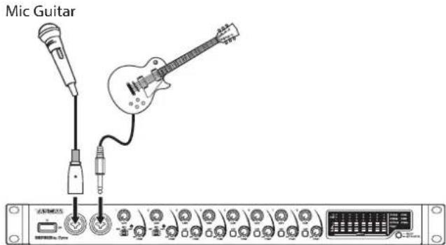
Connecting microphones
Dynamic mics
Connect these to the 1-2 input jacks on the front or the MIC/LINE INPUT 3-8 jacks on the back of the unit.
Condenser mics
When using a condenser mic that requires phantom power, connect it to the 1-2 input jacks on the front or the MIC/LINE INPUT 3-8 jacks on the back of the unit.
Set the input switch to +48V when connecting them to the 1-2 input jacks on the front of the unit. When an input switch is set to +48V , its +48V indicator on the front of the unit lights.
When connecting them to the MIC/LINE INPUT 3-8 input jacks on the back of the unit, turn their +48V switches on. The +48V switches light when they are on.
CAUTION
Set the GAIN and COMP knobs to their minimum values before changing input switch or +48V switch settings. Failure to do so could cause sudden loud noises from monitoring equipment, and this could damage equipment or harm hearing.
ATTENTION
- Input switches can be set for each channel separately. Do not set the switch to +48V when connecting a mic that does not require phantom power.
- Do not connect or disconnect mics when the switch is set to +48V. Doing so could cause a loud noise and might damage this unit and connected equipment.
- Set the switch to +48V only when using a condenser microphone that requires phantom power. Setting the switch to +48V when a dynamic mic or other device that does not require it is connected could damage this unit and connected equipment.
- +48V switches can be set for each channel separately. Do not turn a +48V switch on when connecting a mic that does not require phantom power.
- Do not connect or disconnect mics when a +48V switch is on. Doing so could cause a loud noise and might damage this unit and connected equipment.
- Turn a +48V switch on only when using a condenser mic that requires phantom power. Turning a +48V switch on when a dynamic mic or other mic that does not require it is connected could damage this unit and connected equipment.
- Supplying phantom power to some ribbon mics could break them. If you are unsure, do not supply phantom power to a ribbon mic.
Connecting guitars and basses
When connecting a guitar, bass guitar or other high-impedance output directly to this unit, use input jack 1 or 2 on the front of the unit and set its input switch to INST.
NOTE
When connecting an instrument with active output or when the sound passes through an effects unit, for example, set the input switch to MIC/LINE
Connecting electronic devices and other audio equipment
When connecting an electronic instrument or other audio equipment, for example, to this unit, use a 1-2 jack on the front of the unit and set its input switch to MIC/LINE.
Connecting analog record players
The output of an analog record player cannot be connected directly to this unit. To connect an analog record player to this unit, a phono amp and equalizer (or an audio amplifier that has phono input jacks) must be connected between them.
Connecting digital equipment
Connect an OPTICAL OUT (S/MUX) connector on this unit to an S/MUX input connector on a digital device.
Switching the sample clock
Set the sample clock source to the unit's internal clock, and set the sampling frequency.
The sample clock source can also be set to an external clock (WORD IN).
- Press and hold the sample clock switch to put the unit into sample clock setup mode.
The selected sample clock source will blink repeatedly at short intervals.
- Press the sample clock switch to change the sample clock source.
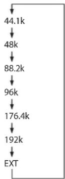
- After selecting the sample clock source, press and hold the sample clock switch to confirm the setting.
NOTE
- This setting is retained even when the unit is turned off.
- When the EXT indicator is blinking and a valid word clock signal is being input through the WORD IN connector, the corresponding sample clock indicator will blink.
Synchronizing with digital devices
Using an OPTICAL OUT (S/MUX) of this unit as the clock source master
The signal output from an OPTICAL OUT (S/MUX) connector of this unit can be used as the master clock to synchronize with connected devices.
Use the sample clock switch (9) to set the sample clock, causing the corresponding indicator (13) to light. (see "Switching the sample clock" on page 12)
Using the word clock of this unit as the clock master
The signal output from the WORD OUT connector of this unit can be used as the master clock to synchronize connected devices.
Set the connected device to accept external clock input.
Using the word clock of an external device as the master clock
The signal input through the WORD IN connector of this unit can be used as the master clock to synchronize with connected devices.
Use the sample clock switch (9) to set the source to EXT. (see "Switching the sample clock" on page 12)
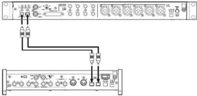
Making connections to use an OPTICAL OUT (S/MUX) of this unit as the clock master
This connection method is also suitable for other audio interfaces with OPTICAL IN connectors.
44.1/48kHz sampling frequency connection examples
TASCAM SERIES 8p Dyna
TASCAM SERIES 102i
Connecting this unit with a SERIES 102i
TASCAM SERIES 8p Dyna
TASCAM SERIES 208i
Connecting this unit with a SERIES 208i
Cable connections
- Use an optical cable to connect an OPTICAL OUT (S/MUX) connector of this unit to an OPTICAL IN (S/MUX) connector of a TASCAM SERIES 102i/208i. Use one optical cable to connect to either the A or B connector.
Setting the sample clock source
- Use the sample clock switch to set the clock source of this unit. (see "Switching the sample clock" on page 12)
- To set the clock source of the TASCAM SERIES 102i/208i, set the Settings Panel INFORMATION screen Sample Clock Source item to "OPTICAL A" or "OPTICAL B" (SERIES 208i only).
When the sample frequency is 88.2/96kHz (S/MUX2) or 176.4/192kHz (S/MUX4)
TASCAM SERIES 8p Dyna
TASCAM SERIES 208i
Cable connections
- Use 2 optical cables to connect the OPTICAL OUT (S/MUX) connectors of this unit to the OPTICAL IN (S/MUX) connectors of a TASCAM SERIES 208i.
Setting the sample clock source
- Use the sample clock switch to set the clock source of this unit. (see "Switching the sample clock" on page 12)
- To set the clock source of the TASCAM SERIES 208i, set the Settings Panel INFORMATION screen Sample Clock Source item to "OPTICAL A" or "OPTICAL B".
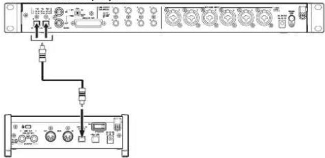
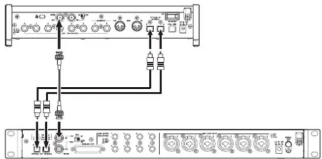
Making connections to use the word clock of this unit as the clock master
This connection method also applies to other audio interfaces with WORD IN connectors.
Connection example when using the word clock of this unit as the clock master at a 44.1/48kHz sampling frequency
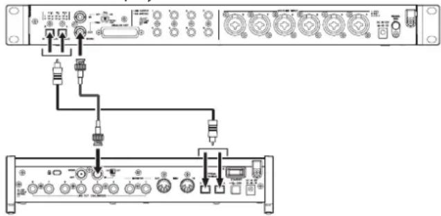
TASCAM SERIES 8p Dyna
TASCAM SERIES 208i
Cable connections
- Use one optical cable to connect either the A or B OPTICAL OUT (S/MUX) connector of this unit to the A or B OPTICAL IN (S/MUX) connector of a TASCAM SERIES 208i.
- Use a BNC cable to connect the WORD OUT connector of this unit to the WORD IN connector of a TASCAM SERIES 208i.
Setting the switch
- Set the TASCAM SERIES 208i 75 ON/OFF switch to ON.
- Set the 75Ω ON/OFF/THRU/WORD OUT switch on this unit to WORD OUT.
Setting the sample clock source
- Use the sample clock switch to set the clock source of this unit. (see "Switching the sample clock" on page 12)
- To set the clock source of the TASCAM SERIES 208i, set the Settings Panel INFORMATION screen Sample Clock Source item to "WORD".
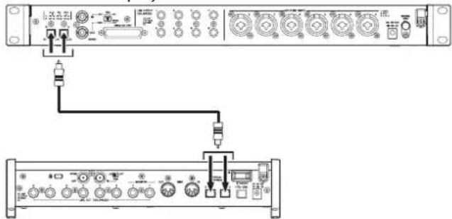
Connection example when using the word clock of this unit as the clock master at 88.2/96kHz (S/MUX2) or 176.4/192kHz (S/MUX4) sampling frequencies
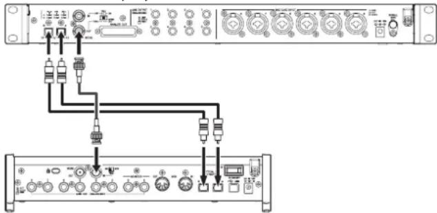
TASCAM SERIES 8p Dyna
TASCAM SERIES 208i
Cable connections
- Use 2 optical cables to connect the OPTICAL OUT (S/MUX) connectors of this unit to the OPTICAL IN (S/MUX) connectors of a TASCAM SERIES 208i.
- Use a BNC cable to connect the WORD OUT connector of this unit to the WORD IN connector of a TASCAM SERIES 208i.
Setting the switch
- Set the TASCAM SERIES 208i 75Ω ON/OFF switch to ON.
- Set the 75Ω ON/OFF/THRU/WORD OUT switch on this unit to WORD OUT.
Setting the sample clock source
- Use the sample clock switch to set the clock source of this unit. (see "Switching the sample clock" on page 12)
- To set the clock source of the TASCAM SERIES 208i, set the Settings Panel INFORMATION screen Sample Clock Source item to "WORD".
Making connections to use the word clock of a connected unit as the clock master
These connection settings also apply to other audio interfaces with WORD OUT connectors.
Connection example when using the word clock of a connected device as the clock master at a 44.1/48kHz sampling frequency
TASCAM SERIES 208i
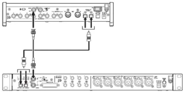
TASCAM SERIES 8p Dyna
Cable connections
- Use one optical cable to connect either the A or B OPTICAL IN (S/MUX) connector of a TASCAM SERIES 208i to the A or B OPTICAL OUT (S/MUX) connector of this unit.
- Use a BNC cable to connect the WORD OUT connector of a TASCAM SERIES 208i to the WORD IN connector of this unit.
Setting the switch
- Set the 75Ω ON/OFF/THRU/WORD OUT switch on this unit to ON.
Setting the sample clock source
- To set the clock source of the TASCAM SERIES 208i, set the Settings Panel INFORMATION screen Sample Clock Source item to "INTERNAL".
- Use the sample clock switch to set the clock source of this unit to EXT. (see "Switching the sample clock" on page 12)
Connection example when using the word clock of a connected device as the clock master at 88.2/96kHz (S/MUX2) or 176.4/192kHz (S/MUX4) sampling frequencies
TASCAM SERIES 208i
TASCAM SERIES 8p Dyna
Cable connections
- Use 2 optical cables to connect the OPTICAL IN (S/MUX) connectors of a TASCAM SERIES 208i to the OPTICAL OUT (S/MUX) connectors of this unit.
- Use a BNC cable to connect the WORD OUT connector of a TASCAM SERIES 208i to the WORD IN connector of this unit.
Setting the switch
- Set the 75Ω ON/OFF/THRU/WORD OUT switch on this unit to ON.
Setting the sample clock source
- To set the clock source of the TASCAM SERIES 208i, set the Settings Panel INFORMATION screen Sample Clock Source item to "INTERNAL".
- Use the sample clock switch to set the clock source of this unit-to EXT. (see "Switching the sample clock" on page 12)
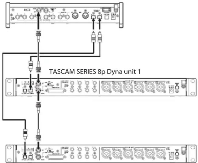
Connecting two of these units to synchronize them
Increasing the number of input channels to 16 is possible by connecting two of these units and synchronizing their clocks.
Connection example when using the word clock of this unit as the clock master
TASCAM SERIES 8p Dyna unit 1
TASCAM SERIES 208i
Cable connections
- Use optical cables to connect OPTICAL OUT (S/MUX) connectors of two of these units to the OPTICAL IN (S/MUX) connectors of a TASCAM SERIES 208i.
- Use a BNC cable to connect the WORD OUT connector of the first of these units (TASCAM SERIES 8p Dyna unit 1) to the WORD IN connector of the second unit (TASCAM SERIES 8p Dyna unit 2).
- Use a BNC cable to connect the WORD OUT connector of the second of these units (TASCAM SERIES 8p Dyna unit 2) to the WORD IN connector of a TASCAM SERIES 208i.
Setting the switch
- Set the 75Ω ON/OFF/THRU/WORD OUT switch on the second unit (TASCAM SERIES 8p Dyna unit 2) to THRU.
- Set the TASCAM SERIES 208i 75Ω ON/OFF switch to ON.
Setting the sample clock source
- Use the sample clock switch to set the clock source of the first of these units (SERIES 8p Dyna unit 1). (see "Switching the sample clock" on page 12)
- Use the sample clock switch to set the clock source of the second unit (slave unit) to EXT. (see "Switching the sample clock" on page 12)
- To set the clock source of the TASCAM SERIES 208i, set the Settings Panel INFORMATION screen Sample Clock Source item to "WORD".
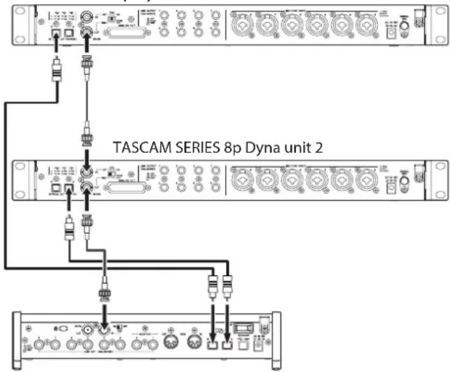
Connection example when using the word clock of a TASCAM SERIES 208i unit as the clock master
TASCAM SERIES 208i
TASCAM SERIES 8p Dyna unit 2
Cable connections
- Use optical cables to connect OPTICAL OUT (S/MUX) connectors of two of these units to the OPTICAL IN (S/MUX) connectors of a TASCAM SERIES 208i.
- Use a BNC cable to connect the WORD OUT connector of a TASCAM SERIES 208i to the WORD IN connector of the first unit (TASCAM SERIES 8p Dyna unit 1).
- Use a BNC cable to connect the WORD OUT connector of the first of these units (TASCAM SERIES 8p Dyna unit 1) to the WORD IN connector of the second unit (TASCAM SERIES 8p Dyna unit 2).
Setting the switch
- Set the 75Ω ON/OFF/THRU/WORD OUT switch on the first unit (TASCAM SERIES 8p Dyna unit 1) to THRU.
- Set the 75Ω ON/OFF/THRU/WORD OUT switch on the second unit (TASCAM SERIES 8p Dyna unit 2) to ON.
Setting the sample clock source
- Use the sample clock switches to set the clock sources on these two units to EXT. (see "Switching the sample clock" on page 12)
- To set the clock source of the TASCAM SERIES 208i, set the Settings Panel INFORMATION screen Sample Clock Source item to "INTERNAL".
Specifications
Ratings
Sampling frequencies
44.1, 48, 88.2, 96, 176.4, 192 kHz
Quantization bit depth
24-bit
Input channels
8 channels
Analog output channels
8 channels
OPTICAL OUT (S/MUX) output channels
8 channels S/MUX (44.1/48kHz)
A: Channels 1-8
B: Channels 1-8
8 channels S/MUX2 (88.2/96kHz)
A:Channels 1-4
B:Channels 5-8
4 channels S/MUX4 (176.4/192kHz)
A: Channels 1-2
B: Channels 3-4
Analog audio input ratings
Mic inputs (balanced)
Front panel 1-2 input jacks
(when the input switch is set to MIC/LINE)
Rear panel MIC/LINE INPUT 3-8 jacks
Connector: XLR-3-31 equivalent (1: GND, 2: HOT, 3: COLD)
Input impedance: 2.2k
Rated input level:
-58 dBu (0.001 Vrms, GAIN knob at maximum)
-6 dBu (0.388 Vrms, GAIN knob at minimum)
Maximum input level: +10 dBu (2.45 Vrms)
Gain range: 52 dB
Instrument inputs (unbalanced)
Front panel 1-2 input jacks
(when the input switch is set to INST)
Connectors: 6.3mm (1 / 4^ ) standard TS jacks
(Tip: HOT, Sleeve: GND)
Input impedance: 900k or higher
Rated input level:
-58 dBV (0.0012 Vrms, GAIN knob at maximum)
-6 dBV (0.501 Vrms, GAIN knob at minimum)
Maximum input level: +10 dBV (3.162 Vrms)
Gain range: 52 dB
Line inputs (balanced)
Front panel 1-2 input jacks
(when the input switch is set to MIC/LINE)
Rear panel MIC/LINE INPUT 3-8 jacks
Connectors: 6.3mm (1/4") standard TRS jacks
(Tip: HOT, Ring: COLD, Sleeve: GND)
Input impedance: 10k
Rated input level:
-48 dBu (0.0003 Vrms, GAIN knob at maximum)
+4 dBu (1.228 Vrms, GAIN knob at minimum)
Maximum input level: +24 dBu (12.282 Vrms)
Gain range: 52 dB
Compressor
3:1 ratio
30dB threshold range
Analog outputs
Analog output (balanced, ANALOG OUT)
Connector: D-sub 25-pin
Locking screws: No. 4-40 UNC (inch type)
Nominal output level: +4 dBu (1.228 Vrms)
Maximum output level: +20 dBu (7.75 Vrms)
Output impedance: 200 or lower
Applicable load impedance: 2k or higher
Line outputs (balanced, LINE OUTPUT 1-8)
Connectors: 6.3mm (1/4") standard TRS jacks
(Tip: HOT, Ring: COLD, Sleeve: GND)
Output impedance: 200 or lower
Nominal output level: +4 dBu (1.228 Vrms)
Maximum output level: +20 dBu (7.75 Vrms)
Digital audio output ratings
OPTICAL OUT (S/MUX)
Connectors: OPTICAL (JEITA RC-5720C)
Signal format: Multi-channel optical format
(supports S/MUX2 and S/MUX4 when 88.2, 96, 176.4 or
192 kHz)
Control input/output
WORD IN connector
Connector: BNC
Input voltage: 2.0 Vpp - 5.0 Vpp
Input impedance: 75 ± 10%
Permitted frequency deviation during external
synchronization: ± 100 ppm
Terminal on/off switch
WORD OUT connector
Connector: BNC
Output voltage: 2.0Vpp (into 75Ω)
Output impedance: 75 ± 10%
Sampling frequencies: 44.1, 48, 88.2, 96, 176.4 and 192kHz
OUT/THRU switch
Audio performance
Mic amp EIN (equivalent input noise)
-127 dBu or lower
Analog input and output
Frequency response
MIC/LINE LINE OUT
20 Hz - 40 kHz: ±0.5 dB (JEITA), 40 kHz - 80 kHz: ±5 dB (JEITA)
S/N ratio
116 dB
(MIC/LINE/INST to LINE OUT, GAIN knob at minimum, JEITA)
Distortion
0.0007%
(MIC/LINE to LINE OUT, 1kHz sine wave, maximum input level, GAIN knob at minimum)
0.0009%
(INST to LINE OUT, 1kHz sine wave, maximum input level, GAIN knob at minimum)
Crosstalk
119 dB
(MIC to LINE OUT, 1kHz sine wave, GAIN knob at minimum)
Analog input to digital output (S/MUX)
Frequency response
MIC/LINE (analog) to digital output (S/MUX)
At 44.1/48 kHz and 20 Hz - 20 kHz: ±0.5 dB (JEITA)
At 88.2/96 kHz and 20 Hz - 40kHz: ±0.5 dB (JEITA)
At 176.4/192 kHz and 20 Hz - 80 kHz: ±5 dB (JEITA)
S/N ratio
113 dB (44.1/48 kHz)
113 dB (88.2/96 kHz)
111 dB (176.4/192 kHz)
(MIC/LINE/INST to digital output (S/MUX), GAIN knob at minimum, JEITA)
Distortion
0.001%
(MIC/LINE/INST to digital output (S/MUX), 1kHz sine wave, maximum input level, GAIN knob at minimum)
Crosstalk
114dB
(MIC (analog) to digital output (S/MUX), 1kHz sine wave, GAIN knob at minimum)
General
Power
DC12V AC adapter (PS-P1230)
Power consumption
16W
Dimensions
482× 44.8× 228.8mm W x H x D, including protrusions)
Weight
2.6 kg
Operating temperature range
0-40°C(32-104°F)
Dimensional drawings

- Illustrations in this manual might differ in part from the actual product.
- Specifications and external appearance might be changed without notification to improve the product.
INSTRUCTIONS DE SECURITE IMPORTANTES
AVERTISSEMENT:POUR PREVENIR LES RISQUES D'INCENDIE ET D'LECTROCUTION,N'EXPOSEZ PAS CET APPAREIL A LA PLUIE NI A L'HUMIDITE.
Pour le Canada
THIS CLASS B DIGITAL APPARATUS COMPLIES WITH CANADIAN ICES-003.
CET APPAREIL NUMÉRIQUE DE LA CLASSE B EST CONFORME À LA NORME NMB-003 DU CANADA.

TASCAM ML-16D
TASCAM Model 24
44,1,48,88,2,96,176,4,192 kHz
113 dB (44,1/48 kHz)
113 dB (88,2/96 kHz)
111 dB (176,4/192 kHz)
Responsible: TEAC AMERICA, INC.
Dirección: 10410 Pioneer Blvd. Suite #1, Santa Fe Springs, California 90670, U.S.A.
Alternatively, you can use the following instructions to start with the following pages.
Characteristicas
⑧ Interruptor/indicator +48V
14 Conectores OPTICAL OUT (S/MUX)
Estos conectores dan salute a una seals audio digital multicanal en formattingo optic.
Admiten frequencies de muestreo de 44.1, 48, 88.2, 96, 176.4 y 192kHz
15 Conectores WORD IN/OUT
20 Conector DC IN 12V
Conectequiryeladaptadorde corriente (PS-P1230)incluso.
② Conector SIGNAL GND
Interruptor Terminal on/off
Conector WORD OUT
Conector: BNC
Voltaje de salute: 2.0 Vpp (a 75 Ω)
113 dB (44.1/48 kHz)
113 dB (88.2/96 kHz)
111 dB (176.4/192 kHz)
(MIC/LINE/INST a entrega digital (S/MUX), mando GAIN al minimo, JEITA)
Distorsión
0.001%
(MIC/LINE/INST a salsa digital (S/MUX), onda sinusoidal 1 kHz, nivel de entrada máximo, mando GAIN al minimum)
Crosstalk cruce de senal
114dB
(MIC (analogico) a salute digital (S/MUX), onda sinusoidal 1 kHz, mando GAIN al minimo)
General
Alimentación
- XLR (1: GND, 2: HOT, 3: COLD)
- TRS (Tip: HOT, Ring: COLD, Sleeve: GND)
14 Connettori OPTICAL OUT (S/MUX)
15 Connettori WORD IN/OUT
16 Interrupttore 75Ω ON/OFF/THRU/WORD OUT
XLR (1: GND, 2: HOT, 3: COLD)
- TRS (Tip: HOT, Ring: COLD, Sleeve: GND)
113 dB (44.1/48 kHz)
113 dB (88.2/96 kHz)
111 dB (176.4/192 kHz)
| 警告 以下の内容を無視て誤った取扱すると、人死亡たは重傷を負う可能性が想定いたします。 | |
| ACアダフローの電源TPL格をCONsesntか根に拔く | 万一、異常が起きたら 煙が出た、変なにしだい音がする)+(1)きは 機器の内部に異物や水/etcが入った)+(2)きは This/It's the only way to get a better idea. ごの機器を落諸了、カバーネを破損たきは すくに機器本体の電源を切り、必すACアダフローの電源TPL格をCONsesntか根に拔て<(3)きは 異常状態のまえ使用 ,(火災・感電的原因)+(4)きは お買申請の販売店まえはテリアツク修理CENTaur(卷末に記載)に修理をご依頸<(5)きは |
| 指示 | ACアダフローの電源TPL格にほこりをたけない ACアダフローの電源TPL格とCONsesntの間にご米やほこりが付着 ,(火災・感電的原因)+(6)きは 定期的(年1回<(7)にACアダフローの電源TPL格を拔て,(乾た布でご米やほこりを取る除て<(8)きは |
| 禁止 | ACアダフローのコードを傷 ,(2)きは ACアダフローの上に重い物 ,(3)きは、ごは壁や棚 ,(4)きは、引は張 ,(5)きは 下敷きに ,(6)きは ACアダフローのコードを加工 ,(7)きは、無理に曲 ,(8)きは、ね ,(9)きは、引は張 ,(10)きは、熱器具に近 }(10)きは コードが傷 ,(11)きは使用 ,(12)きは、感電原因 ,(13)きは 万一、ACアダフローのコードが破損 ,(14)きは(芯線の露出、断線 ,(15)きは はテリアツク修理CENTaur(卷末に記載)をご依頸<(16)きは |
| 付属のACアダフローや電源POLDBを他,(2)機器に使用 ,(3)きは 故障、火災、感電の原因为 ,(4)きは | |
| 交流100円ルト以外の電圧で使用 ,(5)きは This/It's the only way to use it.(6)きは This/It's the only way to use it.(7)きは This/It's the only way to use it.(8)きは This/It's the only way to use it.(9)きは This/It's the only way to use it.(10)きは This/It's the only way to use it.(11)きは This/It's the only way to use it.(12)きは This/It's the only way to use it.(13)きは This/It's the only way to use it.(14)きは This/It's the only way to use it.(15)きは This/It's the only way to use it.(16)きは This/It's the only way to use it.(17)きは This/It's the only way to use it.(18)きは This/It's the only way to use it.(19)きは This/It's the only way to use it.(20)きは This/It's the only way to use it.(21)きは This/It's the only way to use it.(22)きは This/It's the only way to use it.(23)きは This/It's the only way to use it.(24)きは This/It's the only way to use it.(25)きは This/It's the only way to use it.(26)きは This/It's the only way to use it.(27)きは This/It's the only way to use it.(28)きは This/It's the only way to use it.(29)きは This/It's the only way to use it.(30)きは This/It's the only way to use it.(31)きは This/It's the only way to use it.(32)きは This/It's the only way to use it.(33)きは This/It's the only way to use it.(34)きは This/It's the only way to use it.(35)きは This/It's the only way to use it.(36)きは This/It's the only way to use it.(37)きは This/It's the only way to use it.(38)きは This/It's the only way to use it.(39)きは This/It's the only way to use it.(40)きは This/It's the only way to use it.(41)きは This/It's the only way to use it.(42)きは This/It's the only way to use it.(43)きは This/It's the only way to use it.(44)きは This/It's the only way to use it.(45)きは This/It's the only way to use it.(46)きは This/It's the only way to use it.(47)きは This/It's the only way to use it.(48)きは This/It's the only way to use it.(49)きは This/It's the only way to use it.(50)きは This/It's the only way to use it.(51)きは This/It's the only way to use it.(52)きは This/It's the only way to use it.(53)きは This/It's the only way to use it.(54)きは This/It's the only way to use it.(55)きは This/It's the only way to use it.(56)きは This/It's the only way to use it.(57)きは This/It's the only way to use it.(58)きは This/It's the only way to use it.(59)きは This/It's the only way to use it.(60)きは This/It's the only way to use it.(61)きは This/It's the only way to use it.(62)きは This/It's the only way to use it.(63)きは This/It's the only way to use it.(64)きは This/It's the only way to use it.(65)きは This/It's the only way to use it.(66)きは This/It's the only way to use it.(67)きは This/It's the only way to use it.(68)きは This/It's the only way to use it.(69)きは This/It's the only way to use it.(70)きは This/It's the only way to use it.(71)きは This/It's the only way to use it.(72)きは This/It's the only way to use it.(73)きは This/It's the only way to use it.(74)きは This/It's the only way to use it.(75)きは This/It's the only way to use it.(76)きは This/It's the only way to use it.(77)きは This/It's the only way to use it.(78)きは This/It's the only way to use it.(79)きは This/It's the only way to use it.(80)きは This/It's the only way to use it.(81)きは This/It's the only way to use it.(82)きは This/It's the only way to use it.(83)きは This/It's the only way to use it.(84)きは This/It's the only way to use it.(85)きは This/It's the only way to use it.(86)きは This/It's the only way to use it.(87)きは This/It's the only way to use it.(88)きは This/It's the only way to use it.(89)きは This/It's the only way to use it.(90)きは This/It's the only way to use it.(91)きは This/It's the only way to use it.(92)きは This/It's the only way to use it.(93)きは This/It's the only way to use it.(94)きは This/It's the only way to use it.(95)きは This/It's the only way to use it.(96)きは This/It's the only way to use it.(97)きは This/It's the only way to use it.(98)きは This/It's the only way to use it.(99)きは This/It's the only way to use it.(100)きは This/It's the only way to use it.(101)きは This/It's the only way to use it.(102)きは This/It's the only way to use it.(103)きは This/It's the only way to use it.(104)きは This/It's the only way to use it.(105)きは This/It's the only way to use it.(106)きは This/It's the only way to use it.(107)きは This/It's the only way to use it.(108)きは This/It's the only way to use it.(109)きは This/It's the only way to use it.(110)きは This/It's the only way to use it.(111)きは This/It's the only way to use it.(112)きは This/It's the only way to use it.(113)きは This/It's the only way to use it.(114)きは This/It's the only way to use it.(115)きは This/It's the only way to use it.(116)きは This/It's the only way to use it.(117)きは This/It's the only way to use it.(118)きは This/It's the only way to use it.(119)きは This/It's the only way to use it.(120)きは This/It's the only way to use it.(121)きは This/It's the only way to use it.(122)きは This/It's the only way to use it.(123)きは This/It's the only way to use it.(124)きは This/It's the only way to use it.(125)きは This/It's the only way to use it.(126)きは This/It's the only way to use it.(127)きは This/It's the only way to use it.(128)きは This/It's the only way to use it.(129)きは This/It's the only way to use it.(130)きは This/It's the only way to use it.(131)きは This/It's the only way to use it.(132)きは This/It's the only way to use it.(133)きは This/It's the only way to use it.(134)きは This/It's the only way to use it.(135)きは This/It's the only way to use it.(136)きは This/It's the only way to use it.(137)きは This/It's the only way to use it.(138)きは This/It's the only way to use it.(139)きは This/It's the only way to use it.(140)きは This/It's the only way to use it.(141)きは This/It's the only way to use it.(142)きは This/It's the only way to use it.(143)きは This/It's the only way to use it.(144)きは This/It's the only way to use it.(145)きは This/It's the only way to use it.(146)きは This/It's the only way to use it.(147)きは This/It's the only way to use it.(148)きは This/It's the only way to use it.(149)きは This/It's the only way to use it.(150)きは This/It's the only way to use it.(151)きは This/It's the only way to use it.(152)きは This/It's the only way to use it.(153)きは This/It's the only way to use it.(154)きは This/It's the only way to use it.(155)きは This/It's the only way to use it.(156)きは This/It's the only way to use it.(157)きは This/It's the only way to use it.(158)きは This/It's the only way to use it.(159)きは This/It's the only way to use it.(160)きは This/It's the only way to use it.(161)きは This/It's the only way to use it.(162)きは This/It's the only way to use it.(163)きは This/It's the only way to use it.(164)きは This/It's the only way to use it.(165)きは This/It's the only way to use it.(166)きは This/It's the only way to use it.(167)きは This/It's the only way to use it.(168)きは This/It's the only way to use it.(169)きは This/It's the only way to use it.(170)きは This/It's the only way to use it.(171)きは This/It's the only way to use it.(172)きは This/It's the only way to use it.(173)きは This/It's the only way to use it.(174)きは This/It's the only way to use it.(175)きは This/It's the only way to use it.(176)きは This/It's the only way to use it.(177)きは This/It's the only way to use it.(178)きは This/It's the only way to use it.(179)きは This/It's the only way to use it.(180)きは This/It's the only way to use it.(181)きは This/It's the only way to use it.(182)きは This/It's the only way to use it.(183)きは This/It's the only way to use it.(184)きは This/It's the only way to use it.(185)きは This/It's the only way to use it.(186)きは This/It's the only way to use it.(187)きは This/It's the only way to use it.(188)きは This/It's the only way to use it.(189)きは This/It's the only way to use it.(190)きは This/It's the only way to use it.(191)きは This/It's the only way to use it.(192)きは This/It's the only way to use it.(193)きは This/It's the only way to use it.(194)きは This/It's the only way to use it.(195)きは This/It's the only way to use it.(196)きは This/It's the only way to use it.(197)きは This/It's the only way to use it.(198)きは This/It's the only way to use it.(200)きは This/It's the only way to use it.(201)きは This/It's the only way to use it.(202)きは This/It's the only way to use it.(203)きは This/It's the only way to use it.(204)きは This/It's the only way to use it.(205)きは This/It's the only way to use it.(206)きは This/It's the only way to use it.(207)きは This/It's the only way to use it.(208)きは This/It's the only way to use it.(209)きは This/It's the only way to use it.(210)きは This/It's the only way to use it.(211)きは This/It's the only way to use it.(212)きは This/It's the only way to use it.(213)きは This/It's the only way to use it.(214)きは This/It's the only way to use it.(215)きは This/It's the only way to use it.(216)きは This/It's the only way to use it.(217)きは This/It's the only way to use it.(218)きは This/It's the only way to use it.(219)きは This/It's the only way to use it.(220)きは This/It's the only way to use it.(221)きは This/It's the only way to use it.(222)きは This/It's the only way to use it.(223)きは This/It's the only way to use it.(224)きは This/It's the only way to use it.(225)きは This/It's the only way to use it.(226)きは This/It's the only way to use it.(227)きは This/It's the only way to use it.(228)きは This/It's the only way to use it.(229)きは This/It's the only way to use it.(230)きは This/It's the only way to use it.(231)きは This/It's the only way to use it.(232)きは This/It's the only way to use it.(233)きは This/It's the only way to use it.(234)きは This/It's the only way to use it.(235)きは This/It's the only way to use it.(236)きは This/It's the only way to use it.(237)きは This/It's the only way to use it.(238)きは This/It's the only way to use it.(239)きは This/It's the only way to use it.(240)きは This/It's the only way to use it.(241)きは This/It's the only way to use it.(242)きは This/It's the only way to use it.(243)きは This/It's the only way to use it.(244)きは This/It's the only way to use it.(245)きは This/It's the only way to use it.(246)きは This/It's the only way to use it.(247)きは This/It's the only way to use it.(248)きは This/It's the only way to use it.(249)きは This/It's the only way to use it.(250)きは This/It's the only way to use it.(251)きは This/It's the only way to use it.(252)きは This/It's the only way to use it.(253)きは This/It's the only way to use it.(254)きは This/It's the only way to use it.(255)きは This/It's the only way to use it.(256)きは This/It's the only way to use it.(257)きは This/It's the only way to use it.(258)きは This/It's the only way to use it.(259)きは This/It's the only way to use it.(260)きは This/It's the only way to use it.(261)きは This/It's the only way to use it.(262)きは This/It's the only way to use it.(263)きは This/It's the only way to use it.(264)きは This/It's the only way to use it.(265)きは This/It's the only way to use it.(266)きは This/It's the only way to use it.(267)きは This/It's the only way to use it.(268)きは This/It's the only way to use it.(269)きは This/It's the only way to use it.(270)きは This/It's the only way to use it.(271)きは This/It's the only way to use it.(272)きは This/It's the only way to use it.(273)きは This/It's the only way to use it.(274)きは This/It's the only way to use it.(275)きは This/It's the only way to use it.(276)きは This/It's the only way to use it.(277)きは This/It's the only way to use it.(278)きは This/It's the only way to use it.(279)きは This/It's the only way to use it.(280)きは This/It's the only way to use it.(281)きは This/It's the only way to use it.(282)きは This/It's the only way to use it.(283)きは This/It's the only way to use it.(284)きは This/It's the only way to use it.(285)きは This/It's the only way to use it.(286)きは This/It's the only way to use it.(287)きは This/It's the only way to use it.(288)きは This/It's the only way to use it.(289)きは This/It's the only way to use it.(290)きは This/It's the only way to use it.(291)きは This/It's the only way to use it.(292)きは This/It's the only way to use it.(293)きは This/It's the only way to use it.(294)きは This/It's the only way to use it.(295)きは This/It's the only way to use it.(296)きは This/It's the only way to use it.(297)きは This/It's the only way to use it.(298)きは This/It's the only way to use it.(300)きは This/It's the only way to use it.(301)きは This/It's the only way to use it.(302)きは This/It's the only way to use it.(303)きは This/It's the only way to use it.(304)きは This/It's the only way to use it.(305)きは This/It's the only way to use it.(306)きは This/It's the only way to use it.(307)きは This/It's the only way to use it.(308)きは This/It's the only way to use it.(309)きは This/It's the only way to use it.(310)きは This/It's the only way to use it.(311)きは This/It's the only way to use it.(312)きは This/It's the only way to use it.(313)きは This/It's the only way to use it.(314)きは This/It's the only way to use it.(315)きは This/It's the only way to use it.(316)きは This/It's the only way to use it.(317)きは This/It's the only way to use it.(318)きは This/It's the only way to use it.(319)きは This/It's the only way to use it.(320)きは This/It's the only way to use it.(321)きは This/It's the only way to use it.(322)きは This/It's the only way to use it.(323)きは This/It's the only way to use it.(324)きは This/It's the only way to use it.(325)きは This/It's the only way to use it.(326)きは This/It's the only way to use it.(327)きは This/It's the only way to use it.(328)きは This/It's the only way to use it.(329)きは This/It's the only way to use it.(330)きは This/It's the only way to use it.(331)きは This/It's the only way to use it.(332)きは This/It's the only way to use it.(333)きは This/It's the only way to use it.(334)きは This/It's the only way to use it.(335)きは This/It's the only way to use it.(336)きは This/It's the only way to use it.(337)きは This/It's the only way to use it.(338)きは This/It's the only way to use it.(339)きは This/It's the only way to use it.(340)きは This/It's the only way to use it.(341)きは This/It's the only way to use it.(342)きは This/It's the only way to use it.(343)きは This/It's the only way to use it.(344)きは This/It's the only way to use it.(345)きは This/It's the only way to use it.(346)きは This/It's the only way to use it.(347)きは This/It's the only way to use it.(348)きは This/It's the only way to use it.(349)きは This/It's the only way to use it.(350)きは This/It's the only way to use it.(351)きは This/It's the only way to use it.(352)きは This/It's the only way to use it.(353)きは This/It's the only way to use it.(354)きは This/It's the only way to use it.(355)きは This/It's the only way to use it.(356)きは This/It's the only way to use it.(357)きは This/It's the only way to use it.(358)きは This/It's the only way to use it.(359)きは This/It's the only way to use it.(360)きは This/It's the only way to use it.(361)きは This/It's the only way to use it.(362)きは This/It's the only way to use it.(363)きは This/It's the only way to use it.(364)きは This/It's the only way to use it.(365)きは This/It's the only way to use it.(366)きは This/It's the only way to use it.(367)きは This/It's the only way to use it.(368)きは This/It's the only way to use it.(369)きは This/It's the only way to use it.(370)きは This/It's the only way to use it.(371)きは This/It's the only way to use it.(372)きは This/It's the only way to use it.(373)きは This/It's the only way to use it.(374)きは This/It's the only way to use it.(375)きは This/It's the only way to use it.(376)きは This/It's the only way to use it.(377)きは This/It's the only way to use it.(378)きは This/It's the only way to use it.(379)きは This/It's the only way to use it.(380)きは This/It's the only way to use it.(381)きは This/It's the only way to use it.(382)きは This/It's the only way to use it.(383)きは This/It's the only way to use it.(384)きは This/It's the only way to use it.(385)きは This/It's the only way to use it.(386)きは This/It's the only way to use it.(387)きは This/It's the only way to use it.(388)きは This/It's the only way to use it.(389)きは This/It's the only way to use it.(390)きは This/It's the only way to use it.(391)きは This/It's the only way to use it.(392)きは This/It's the only way to use it.(393)きは This/It's the only way to use it.(394)きは This/It's the only way to use it.(395)きは This/It's the only way to use it.(396)きは This/It's the only way to use it.(400)きは This/It's the only way to use it.(401) This/It's the only way to use it. | |
| 分解禁止 | その機器の力ローは絶対に外さない力ローを外す、まえは改造いたします、火災・感電の原因为ります。内部の点検・修理はお買上の販売店たはテアック修理senターナー(卷末に記載)にご依賴(<ださい)。 |
| その機器を改造いたします火災・感電の原因为ります。 | |
| 注意 以下の内容を無視て誤った取扱すると、人か傷害を負う可能性が想定之称的内容お願いいたします。 | |
| ACアダフ总冠军の電源总冠军をCONsesstadaから拔く | 移動くださいます场合は、電源のスイチを切り、必すACアダフ总冠军の電源TPLAZをCONSENTADから拔き、外部の接続コeadを外す一棹が傷っ、火災・感電の原因为、引つ掛けだけ的原因に到る它のは).(2)旅行くださいます長期間ごの機器を使用くださいますきや助手接入の際は、安全のたて必すACアダフ总冠军の電源TPLAZをCONSENTADから拔く通電状態の放置や助手接入は、漏電或感電の原因为)+(3)才が通過可能)(4)提示: |
| 指示 | 才一デイ才機器を接続する场合は、各々の機器の取扱説明書をよく讀み、電源を切り、説明にしぃて接続する;(5)未了、接続は指定のコeadを使用%(6)電源を入る前提に、音量を最小に%(7)突然大小な音が出て、聰觉障害等各种原因)+(8) |
| )(9) | |
| )(10) | |
| )(11) | |
| )(12) | |
| )(13) | |
| )(14) | |
| )(15) | |
| )(16) | |
| )(17) | |
| )(18) | |
| )(19) | |
| )(20) | |
| )(21) | |
| )(22) | |
| )(23) | |
| )(24) | |
| )(25) | |
| )(26) | |
| )(27) | |
| )(28) | |
| )(29) | |
| )(30) | |
| )(31) | |
| )(32) | |
| )(33) | |
| )(34) | |
| )(35) | |
| )(36) | |
| )(37) | |
| )(38) | |
| )(39) | |
| )(40) | |
| )(41) | |
| )(42) | |
| )(43) | |
| )(44) | |
| )(45) | |
| )(46) | |
| )(47) | |
| )(48) | |
| )(49) | |
| )(50) | |
| )(51) | |
| )(52) | |
| )(53) | |
| )(54) | |
| )(55) | |
| )(56) | |
| )(57) | |
| )(58) | |
| )(59) | |
| )(60) | |
| )(61) | |
| )(62) | |
| )(63) | |
| )(64) | |
| )(65) | |
| )(66) | |
| )(67) | |
| )(68) | |
| )(69) | |
| )(70) | |
| )(71) | |
| )(72) | |
| )(73) | |
| )(74) | |
| )(75) | |
| )(76) | |
| )(77) | |
| )(78) | |
| )(79) | |
| )(80) | |
| )(81) | |
| )(82) | |
| )(83) | |
| )(84) | |
| )(85) | |
| )(86) | |
| )(87) | |
| )(88) | |
| )(89) | |
| )(90) | |
| )(91) | |
| )(92) | |
| )(93) | |
| )(94) | |
| )(95) | |
| )(96) | |
| )(97) | |
| )(98) | |
| )(99) | |
| )(100) | |
目次
安全にお使いんだたてに 83
はしだに 85
本機の概要 85
本製品の構成 86
本书の表記 86
設置上の注意 86
結露にて 86
製品のお手出入. 86
一登録に. 86
7 87
各部の名称 88
□□t八
LRAA. 90
電源を接続する. 91
TASCAM ML-16D
[SERIES8pDyna使接续例]
才一才の接続
This warranty gives you specific legal rights and you may also have other rights which vary from state to state. This warranty is only valid within the country the unit was originally purchased.
WHAT IS COVERED AND WHAT IS NOT COVERED
Except as specified below, this warranty covers all defects in materials and workmanship in this product. The following are not covered by the warranty:
- Damage to or deterioration of the external cabinet.
- Damage resulting from accident, misuse, abuse or neglect.
- Damage resulting from failure to perform basic daily maintenance and/or calibration or otherwise resulting from failure to follow instructions contained in your owner's manual.
- Damage occurring during shipment of the product. (Claims must be presented to the carrier)
- Damage resulting from repair or attempted repair by anyone other than TEAC or an authorized TASCAM service station.
- Damage resulting from causes other than product defects, including lack of technical skill, competence, or experience of the user.
- Damage to any unit which has been altered or on which the serial number has been defaced, modified or is missing.
WHOIS COVERED UNDER THE WARRANTY
This warranty may be enforced only by the original purchaser. This warranty is not valid if the product was purchased through an unauthorized dealer.
LENGTH OF WARRANTY
All parts except heads and disk drives are warranted for one (1) year from the date of original purchase. Heads and disk drives are warranted for ninety (90) days from date of original purchase. Labor is warranted for ninety (90) days from date of original purchase.
WHAT WE WILL PAY FOR
We will pay all labor and material expenses for items covered by the warranty. Payment of shipping charges is discussed in the next section of this warranty.
HOW YOU CAN GET WARRANTY SERVICE
Your unit must be serviced by an authorized TASCAM service station in the United States. (This warranty is not enforceable outside the U.S.) If you are unable to locate an authorized TASCAM service station in your area, please contact us. We either will refer you to an authorized service station or instruct you to return the unit to the factory. Whenever warranty service is required, you must present a copy of the original dated sales receipt from an Authorized TASCAM Dealer.
You must pay any shipping charges if it is necessary to ship the product to service. However, if the necessary repairs are covered by the warranty, we will pay return surface shipping charges to any destination within the United States.
LIMITATION OF IMPLIED WARRANTYES
Any implied warranties, INCLUDING WARRANTIES OF MERCHANTABILITY AND FITNESS FOR A PARTICULAR PURPOSE, are limited in duration to the length of this warranty.
EXCLUSION OF DAMAGES
TEACS liability for any defective product is limited to repair or replacement of the product, at TEACS option. TEAC shall not be liable for:
- Damages based upon inconvenience, loss of use of the product, loss of time interrupted operation or commercial loss; or
- Any other damages, whether incidental, consequential or otherwise.
Some states do not allow limitations on how long an implied warranty lasts and/or do not allow the exclusion or limitation of incidental or consequential damages, so the above limitations and exclusions may not apply to you.
To locate an Authorized Service Center in Your Area
CALL 1-323-726-0303
< Europe >
This product is subject to the legal warranty regulations of the country of purchase. In case of a defect or a problem, please contact the dealer where you bought the product.
This warranty gives you specific legal rights, and you may also have other rights that vary by country, state or province.
If you have a warranty claim or request, please contact the dealer where you bought the product.
If you require repair services for your TASCAM equipment, please contact the dealer where the product was purchased.
from or the TASCAM Distributor in your country. A list of TASCAM Distributors can be found on our website at
http://teac-global.com/
Address/Adresse/Adresse
Indirizzo/Direccion/住所
Date of purchase / Date de I'ach / Datum des Kauf
- TEAC CORPORATION
- TEAC UK Ltd.
- TEAC EUROPE GmbH
- IMPORTANT SAFETY INSTRUCTIONS
- For U.S.A.
- Declaration of Conformity
- INFORMATION TO THE USER
- CAUTION
- For Canada
- For European Customers
- Disposal of electrical and electronic equipment
- RACK-MOUNTING THE UNIT
- ATTENTION
- Contents
- Introduction
- Features
- Included items
- NOTE
- Conventions used in this manual
- TIP
- About TASCAM customer support service
- Precautions for placement and use
- Beware of condensation
- Cleaning the unit
- Product registration
- Using the TEAC Global Site
- Front panel
- Level meter area details
- ⑩ OL indicators
- COMP indicators
- Level meters
- ③ Sample clock indicators
- Rear panel
- OPTICAL OUT (S/MUX) connectors
- WORD IN/OUT connectors
- 75Ω ON/OFF/THRU/WORD OUT switch
- ⑦ ANALOG OUT connector
- LINE OUT (BALANCED) 1-8 jacks
- MIC/LINE INPUT 3-8 jacks
- DCIN 12V connector
- SIGNAL GND connector
- Cord holder
- Connecting the power
- Changing the outlet plug
- Connecting other equipment
- Precautions before making connections
- Audio connections
- Connecting microphones
- Dynamic mics
- Condenser mics
- Connecting guitars and basses
- Connecting electronic devices and other audio equipment
- Connecting analog record players
- Connecting digital equipment
- Switching the sample clock
- Synchronizing with digital devices
- Using an OPTICAL OUT (S/MUX) of this unit as the clock source master
- Using the word clock of this unit as the clock master
- Using the word clock of an external device as the master clock
- Making connections to use an OPTICAL OUT (S/MUX) of this unit as the clock master
- 44.1/48kHz sampling frequency connection examples
- Cable connections
- Setting the sample clock source
- When the sample frequency is 88.2/96kHz (S/MUX2) or 176.4/192kHz (S/MUX4)
- Making connections to use the word clock of this unit as the clock master
- Connection example when using the word clock of this unit as the clock master at a 44.1/48kHz sampling frequency
- Setting the switch
- Connection example when using the word clock of this unit as the clock master at 88.2/96kHz (S/MUX2) or 176.4/192kHz (S/MUX4) sampling frequencies
- Making connections to use the word clock of a connected unit as the clock master
- Connection example when using the word clock of a connected device as the clock master at a 44.1/48kHz sampling frequency
- Connection example when using the word clock of a connected device as the clock master at 88.2/96kHz (S/MUX2) or 176.4/192kHz (S/MUX4) sampling frequencies
- Connecting two of these units to synchronize them
- Connection example when using the word clock of this unit as the clock master
- Connection example when using the word clock of a TASCAM SERIES 208i unit as the clock master
- Specifications
- Ratings
- Sampling frequencies
- Quantization bit depth
- Input channels
- Analog output channels
- OPTICAL OUT (S/MUX) output channels
- Analog audio input ratings
- Mic inputs (balanced)
- Instrument inputs (unbalanced)
- Line inputs (balanced)
- Compressor
- Analog outputs
- Analog output (balanced, ANALOG OUT)
- Line outputs (balanced, LINE OUTPUT 1-8)
- Digital audio output ratings
- OPTICAL OUT (S/MUX)
- Control input/output
- WORD IN connector
- WORD OUT connector
- Audio performance
- Mic amp EIN (equivalent input noise)
- Analog input and output
- Frequency response
- S/N ratio
- Distortion
- Crosstalk
- Analog input to digital output (S/MUX)
- General
- Power
- Power consumption
- Dimensions
- Weight
- Operating temperature range
- Dimensional drawings
- INSTRUCTIONS DE SECURITE IMPORTANTES
- Pour le Canada
- Characteristicas
- Conectores OPTICAL OUT (S/MUX)
- Conectores WORD IN/OUT
- Conector DC IN 12V
- ② Conector SIGNAL GND
- Conector WORD OUT
- Distorsión
- Crosstalk cruce de senal
- Alimentación
- Connettori OPTICAL OUT (S/MUX)
- Connettori WORD IN/OUT
- Interrupttore 75Ω ON/OFF/THRU/WORD OUT
- 目次
- 才一才の接続
- WHAT IS COVERED AND WHAT IS NOT COVERED
- WHOIS COVERED UNDER THE WARRANTY
- LENGTH OF WARRANTY
- WHAT WE WILL PAY FOR
- HOW YOU CAN GET WARRANTY SERVICE
- LIMITATION OF IMPLIED WARRANTYES
- EXCLUSION OF DAMAGES
- To locate an Authorized Service Center in Your Area
- < Europe >
Brand : TASCAM
Model : SERIES 8p Dyna
Category : Receiver