
HS 2000 - Manual winch Güde - Free user manual and instructions
Find the device manual for free HS 2000 Güde in PDF.
| Product type | Manual winch (lever puller hoist) |
| Brand | Güde |
| Model | HS 2000 |
| Maximum pulling capacity | 2000 kg |
| Cable length | Approximately 2.8 m |
| Cable diameter | 4.5 mm |
| Maximum pulling travel | Approximately 1.3 m |
| Order number | 38350 |
| Material | Galvanized steel, forged steel hooks |
| Hooks | 2 safety load hooks with lock |
| Locking mechanism | Ratchet with 3 protections, lever with 3 rivets |
| Intended use | Pulling loads, tensioning fences, freeing vehicles |
| Prohibition | Lifting loads strictly prohibited |
| Warranty | 24 months for end consumer, 12 months for industrial use |
| Minimum age of use | 16 years (except professional training) |
| Maintenance | Monthly lubrication of moving parts, cable check before each use |
| Weight | Not specified in the manual (estimate: approximately 5 kg) |
| Dimensions | Not specified in the manual |
| Power source | Manual (no electricity) |
| Repairability | Spare parts available via Güde after-sales service |
Frequently Asked Questions - HS 2000 Güde
User questions about HS 2000 Güde
0 question about this device. Answer the ones you know or ask your own.
Ask a new question about this device
Download the instructions for your Manual winch in PDF format for free! Find your manual HS 2000 - Güde and take your electronic device back in hand. On this page are published all the documents necessary for the use of your device. HS 2000 by Güde.
USER MANUAL HS 2000 Güde
Translation of the original instructions Manually controlled lever winch
ENGLISH Please read the instructions carefully before starting the machine.
natural_image
Black-and-white illustration of a person climbing a steep cliff with ropes (no text or symbols)
natural_image
Illustration of a worker using a power pole to lift a wire, no text or symbols present
natural_image
Close-up of hands using a tool to adjust or install a car tire component on a paved surface (no visible text or symbols)Every effort is made to improve our products continuously. Therefore, technical data and figures may change.
Unit
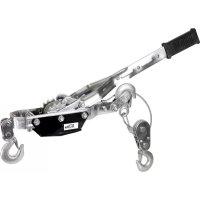
Stable galvanised all-steel structure with 2 stable lockable load-carrying hooks of forged steel. The stretch-slackening spanner with treble protection, lever with three rivets.
Areas of Use:
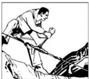
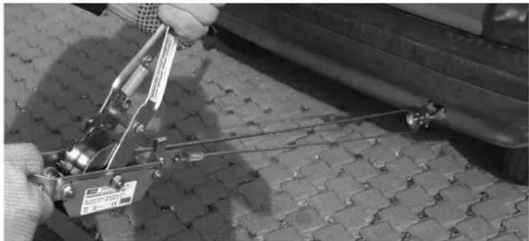
Excellent to draw loads, stretch fences or to serve as an aid to tow disabled vehicles.
Appliance description
- Load carrying hook
- Lock lever
- Rope pulley
- retaining pawl
- stretch spring
- Handle
- Load carrying hook
- Restoring pulley
- Wire rope
Warranty
A warranty period of 12 months applies to commercial use and 24 months apply to private use and commences on the day of purchase of the device.
Warranty applies exclusively to failures due to defective material or workmanship. An original sale slip with indication of date of sale must be presented in case of claiming for the warranty rights.
Warranty does not cover unprofessional use such as device overload, violent use, damage caused by third party or foreign materials, failure to comply with operations and assembly manual, and normal wear and tear.
Safety Instructions
Prior to the initial use of the unit, the operating instructions should be read completely. If in doubt with regard to connection and operation of the unit, consult the manufacturer (servicing department).
FOLLOW THE INSTRUCTIONS BELOW CAREFULLY IN ORDER TO SECURE A HIGH DEGREE OF SAFETY:

CAUTION!
Be advised that should the procedures described below be not observed, a risk arises entailing health hazard, severe injuries or death in a medium term or long-term horizon. Therefore, it is necessary to observe the safety standards shown below that make use of the tension pulley safe.
- Wear the environment-appropriate protection clothing in the course of works and make provisions for injury prevention appropriate to the environment.
• Before putting the unit in operation, make sure that it is complete and functional and that all the screw joints are tight. - Never use a unit that is defective or damaged. If there are cracks or other damages, it should be replaced. If that is the case, contact manufacturer immediately or have the tension pulley checked and repaired at a qualified expert.
- Lever tension pulley should be operated only by persons who have read thoroughly this manual and understood it. The lever tension pulley must not be operated by persons not in good condition of health and those who were not instructed as appropriate.
- The lever tension pulley may be only used for drawing loads, the weight of which is not in excess of maximum carrying capacity shown in the technical characteristics given by the manufacturer and on the pulley plate.
• Always work cautiously and considerably. Do not apply too much force. - Never use the unit as a rope pulley to hoist the loads etc.
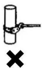
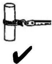
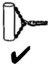
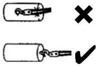
- Never wind the rope around the article to form a loop, in which the hook may be hung. Never put the rope across corners.
• Before stretching the rope winch, always make sure that the hooks are hung on the article properly. - Never use the unit as a towing cable.
- Before getting down to work, all the tension pulley parts should be checked to see that their functioning is perfect. In particular, check the condition of spring hooks that are to prevent unintentional slackening of the hook.
- Have two lengths of the rope wound on the pulley when working.
- Always contact your specialised vendor when problems related to the tension pulley function arise. Avoid any intermediate action.
- Always be careful not to put a part of your body – fingers e.g. – in rotating parts or the parts, which the tension force is applied on.
- Do no let children near the tension pulley.

Caution: It is strictly forbidden to hoist loads.
Behaviour in case of emergency
Provide necessary first aid treatment corresponding to the injury nature and seek qualified medical help as soon as possible. Protect the injured person from other injuries and calm him/her down.
First aid kit must always be available in the place of your work in case of accident in accordance with DIN 13164. Material taken out of the first aid kit needs to be supplemented right away. If help is needed, please provide the following details:
- Place of accident
- Accident nature
- Number of injured persons
- Injury type
Signs on Unit
Meaning of Symbols
Symbols shown below are used throughout this manual and/or on the unit:
Product Safety
| CE | |||||
| Product compliance with respective EU standards |
Bans:
| General ban (in combination with another pictograph) | No reaching | Do not use the unit in wet conditions | Hoisting loads is strictly forbidden. The lever winch may only be used for pulling and tensioning loads within the mentioned range of load. | Appliance to be operated by one person only |
Warning:
| Warning/caution Beware of tripping | Beware of hand injury/contusion | Keep persons standing around in safe distance from the appliance | Risk of drawing-in | ||
Commands:
| Read operating manual before use | Wear protection gloves | Use protection nailed shoes |
Environment Protection
| Wastes to be disposed of in a professional manner not to harm the environment. | Cardboard packaging to be collected for recycling. |
Packaging:
 |  |  |  | ||
| Protect from moisture | Keep Up Fragile | Interseroh-Recycling | |||
Technical Data:
 |  |  |  | ||
| Max. pulling force Cable length Cable thickness max. pulling length | |||||
Intended use
The lever winch may only be used for pulling and tensioning loads within the mentioned range of load. Before use, make sure that the tow point's maximal load is higher than winch's maximal force. The maximal load mentioned in the technical specifications must not be exceeded under any circumstances. Hoisting loads is strictly forbidden.
This appliance must not be used to perform other works than those for which the appliance has been designed and which are described in the Operating Instructions. Any other use is conflict with the designation. The manufacturer is not responsible for any indirect damages and injuries. Please be sure to know that our appliances have not been designed to be used for industrial purposes.
Residual Hazards and Protective Action
Mechanical Residual Hazards
| Hazard Descrip | tion Protecti | ve Action | Residual |
| Catching, winding Loose fitting | clothing and jewels may be caught by the unit | Always wear tight-fitting clothes, put aside any jewels that might be caught by the unit. | |
| Rope breakage The rope may break and severe injury may be caused by backlash. | Do not exceed the determined traction limit. . | ||
| Cutting Torn rope may cause an injury Check the rope! | Wear protection gloves! | ||
| Load deformation The load should be tightened at determined places; otherwise, it may get damaged. | Select points suitable for hanging. | ||
| Extension ropes Extension ropes may break and cause severe injuries. | Check the load of extension ropes in traction. | ||
Human Factor Neglect
| Hazard Description Protective | Action Residual Hazards | ||
| Negligible use of personal protection equipment | Operation of the unit without relevant protection equipment may result I severe external and internal injuries. | Always wear protection clothing and work considerably. | |
Disposal
The disposal instructions are based on icons placed on the appliance or its package. The description of the meanings can be found in the "Marking" chapter.
Transport package disposal
The package protects the appliance against damage during transport. Packing materials are usually chosen depending on their environmental friendliness and disposal method and can therefore be recycled.
Returning the package to material circulation saves raw materials and reduces waste disposal costs.
Parts of packages (e.g. foils, styropor) can be dangerous to children. Risk of suffocation!
Keep parts of packages away from children and dispose them as soon as possible.
Operator Requirements
The operator shall read the instruction manual carefully before using the unit.
Qualification
No special qualification is required for use of the unit except for detailed direction by a professional.
Minimum Age
Only persons above 16 years of age are allowed to work with the unit.
Exempted from the provision is the use of the juvenile trainees if they work in the course of their professional training with an aim to obtain the skill under trainer supervision.
Technical Data
| HS 2000 HS 4000 | ||
| Max. drawing force 2000 kg 4000 kg | ||
| Rope length: ca 2,8 m ca 3 m | ||
| Rope diameter: 4,5 mm 5 mm | ||
| Max. drawing way: ca 1,3 m Ca. 1,4 m | ||
| Ordering Number: 38350 38351 |
other
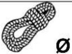
| Shape | Weight (kg) | Angle (°) | Percentage (%) | | :--- | :--- | :--- | :--- | | 2t | 400 | 0.6 | 20 | | 2t | 970 | 1.8 | 60 | | 2t | 1300 | 3 | 100 | | 2t | 1600 | 5.5 | 180 | The chart displays a right triangle with a horizontal base at 10m for reference. The bottom row is labeled 'grade'.Caution:
• Not to be used at a gradient above 180%!
- In displayed examples, the friction coefficient is not included. Mind that any loads without wheels require more power from the rope winch.
- On slopes, the load should be secured against slipping
Procedure
natural_image
Black-and-white illustration of a person climbing a rocky cliff with ropes (no text or symbols)
natural_image
Illustration of a worker using a saw to extend barbed wire (no text or symbols)⚠️ Hand operated winding pulley may be used for drawing loads only. The total weight of the load should not be in excess of data on the plate.
Wires and additional ropes may get broken and cause severe injuries by backlash!
Operator Safety Instructions
- Do not use the unit before you have read the operating manual carefully.
- Observe all the safety instructions indicated in the manual.
- Be responsible to the others.
Operation
Step-by step Instructions
- Hang the counter pulley (pic. 1/8) hook (pic. 1/7), which the rope (pic. 1/9) is attached to, safely on the load drawn.
- Push the stretching spring (5) to the slackening position (up), thus releasing the interlock (4).
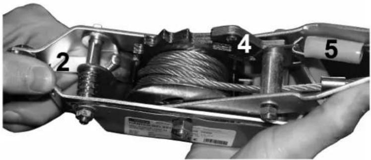
- Rope may be unwound if the detention lever (2) is held in the release position. Hold the detent lever (2) pressed and pull the stretching pulley to the other spot of hanging!

Caution: Travel 1,3 m max. (#38350) 1,4 m max. (#38351)
natural_image
Close-up of hands using a tool to adjust or install a car tire component (no visible text or symbols)- Push the stretching spring (5) to the tensioning position (down), the interlock will thus snap (4) in the pulley.
- Now, pump the lever with a stretch-slackening spanner. The rope will gat wound on the pulley again and the load is drawn in the required position.
- Push the stretching spring (5) to the slackening position (up), thus releasing the interlock (4). If the interlock is unblocked, the load carrying hooks may be removed again.

Attention! The load could break away suddenly.

Caution: On a slope, the load should be secured against slipping!
Troubles – Causes – Troubleshooting
| Trouble | Cause | Troubleshooting |
| Retaining pawl will not unblock | 1. Broken spring 1. Replace the spring | |
| Stretch-straightening spanner does not work | 1. Broken spring 1. Replace the spring |
Inspections and Maintenance
Inspections and Maintenance Safety Instructions
Only a unit maintained and cared for on a regular basis may be a serviceable aid. Insufficient maintenance and care may result in emergencies and unforeseen accidents.
Inspections and Maintenance Schedule
| Time Interval | Description | Other details | as required |
| Monthly | • Lubrication of all the moving parts | ||
| Before every use | • Check of the rope for damages | ||
Servicing
Do you have any technical questions? A claim? Do you need spare parts or the Operating Instructions?
You will be helped quickly and without needless bureaucracy at our webpage www.guede.com in the Service part. Please help us be able to assist you. To be able to identify your appliance when claimed, we need to know its serial No., order No. and year of production. All these details can be found on the type label. Enter the details below for future reference.
Serial No.:
Order No.:
Year of production:
Tel.: +49 (0) 79 04 / 700-360
Fax: +49 (0) 79 04 / 700-51999
E-Mail: support@ts.guede.com
natural_image
Black-and-white illustration of a person climbing a steep slope with ropes (no text or symbols)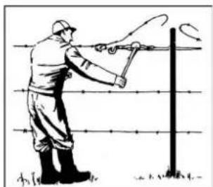
natural_image
Illustration of a worker using a power pole to lift a wire, with barbed wire and ground lines (no text or symbols)
natural_image
Close-up of hands using a tool to adjust or install a car tire component on a paved surface (no visible text or symbols)natural_image
Black-and-white illustration of a person climbing a rope over rocks (no text or symbols)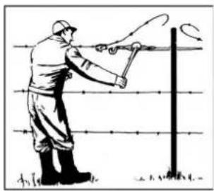
natural_image
Illustration of a worker using a power pole with barbed wire (no text or symbols)
natural_image
Close-up of hands holding a mechanical device with numbered parts (2, 4, 5) and visible internal components (no text or symbols)natural_image
Close-up of hands using a tool to adjust or install a car tire component on a paved surface (no visible text or symbols)natural_image
Black-and-white illustration of a person climbing a rope over a rocky cliff (no text or symbols)
natural_image
Illustration of a worker using a power pole to measure a wire fence (no text or symbols present)
natural_image
Close-up of hands using a tool to adjust or install a car tire component on a paved surface (no visible text or symbols)natural_image
Black-and-white illustration of a person climbing a steep cliff with a tool, no text or symbols present
natural_image
Illustration of a worker using a power pole to lift a wire, no text or symbols present
natural_image
Close-up of hands using a tool to adjust or install a mechanical component on a tiled floor (no visible text or symbols)natural_image
Black-and-white illustration of a person climbing a rocky slope with ropes (no text or symbols)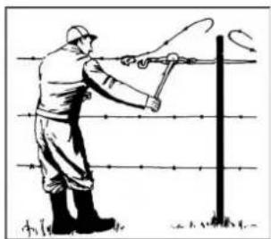
natural_image
Illustration of a worker using a power tool to catch a barbed wire fence (no text or symbols)
natural_image
Close-up of hands using a tool to adjust or install a vehicle component on a paved surface (no visible text or symbols)natural_image
Black-and-white illustration of a person climbing a steep cliff with ropes (no text or symbols)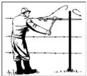
natural_image
Illustration of a worker using a power tool to lift a vertical pole (no text or symbols present)natural_image
Close-up of hands using a tool to adjust or install a car tire component (no visible text or symbols)Translation of the EC-Declaration of Conformity
We, hereby declare the conception and construction of the below mentioned appliances correspond - at the type of construction being launched - to appropriate basic safety and hygienic requirements of EC Directives. In case of any change to the appliance not discussed with us the Declaration expires.
90431 Nürnberg Germany
Type Ex. Cert.-No.:
□97/68/EC_
Emission No.:
2000/14/EC_2005/88/EC
90431 Nürnberg Germany
Type Ex. Cert.-No.:
□ 97/68/EC_
Emission No.:
2000/14/EC_2005/88/EC


- Unit
- Areas of Use:
- Appliance description
- Warranty
- Safety Instructions
- FOLLOW THE INSTRUCTIONS BELOW CAREFULLY IN ORDER TO SECURE A HIGH DEGREE OF SAFETY:
- CAUTION!
- Behaviour in case of emergency
- Signs on Unit
- Meaning of Symbols
- Intended use
- Residual Hazards and Protective Action
- Disposal
- Transport package disposal
- Operator Requirements
- Qualification
- Minimum Age
- Caution:
- Procedure
- ⚠️ Hand operated winding pulley may be used for drawing loads only. The total weight of the load should not be in excess of data on the plate.
- Wires and additional ropes may get broken and cause severe injuries by backlash!
- Operator Safety Instructions
- Operation
- Step-by step Instructions
- Servicing
- Translation of the EC-Declaration of Conformity
Brand : Güde
Model : HS 2000
Category : Manual winch